Chapter 7, ELECTRICAL
Chapter 7, ELECTRICALWiring Diagram
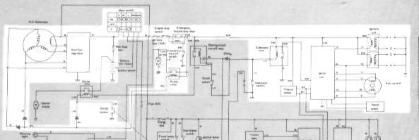
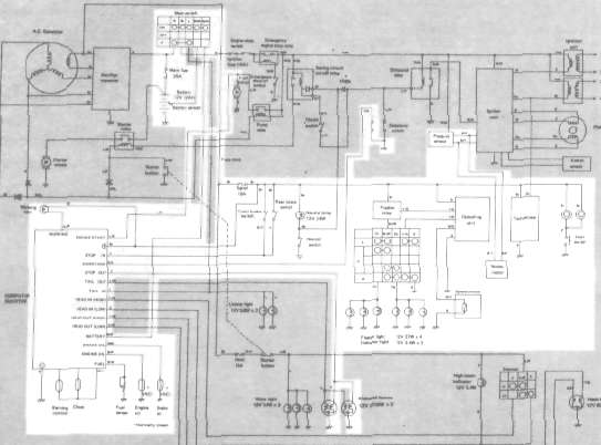
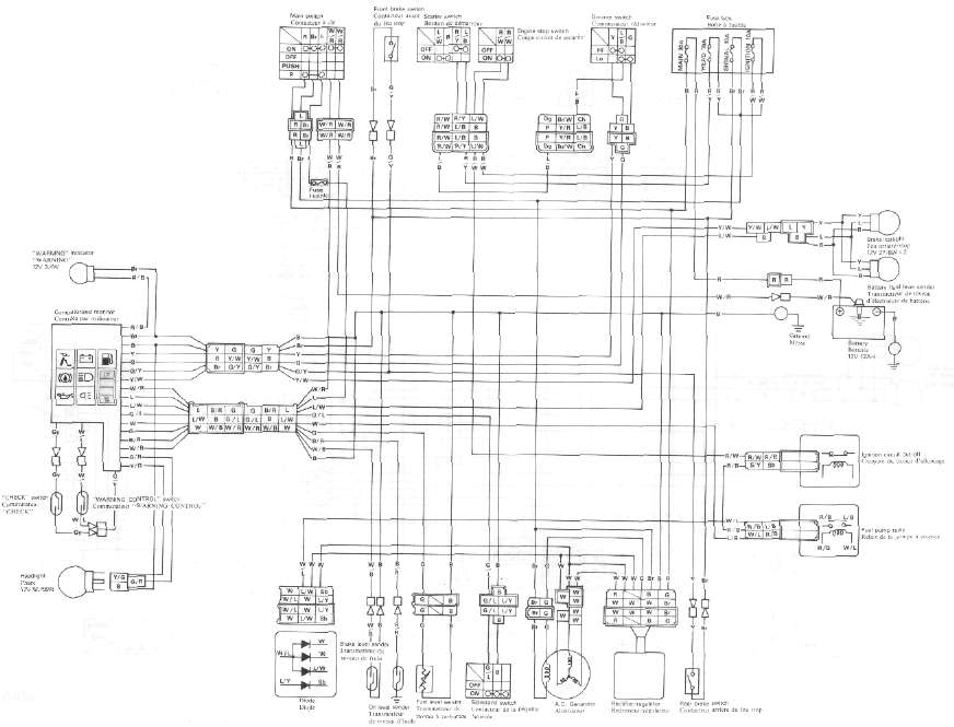
Wiring Diagram
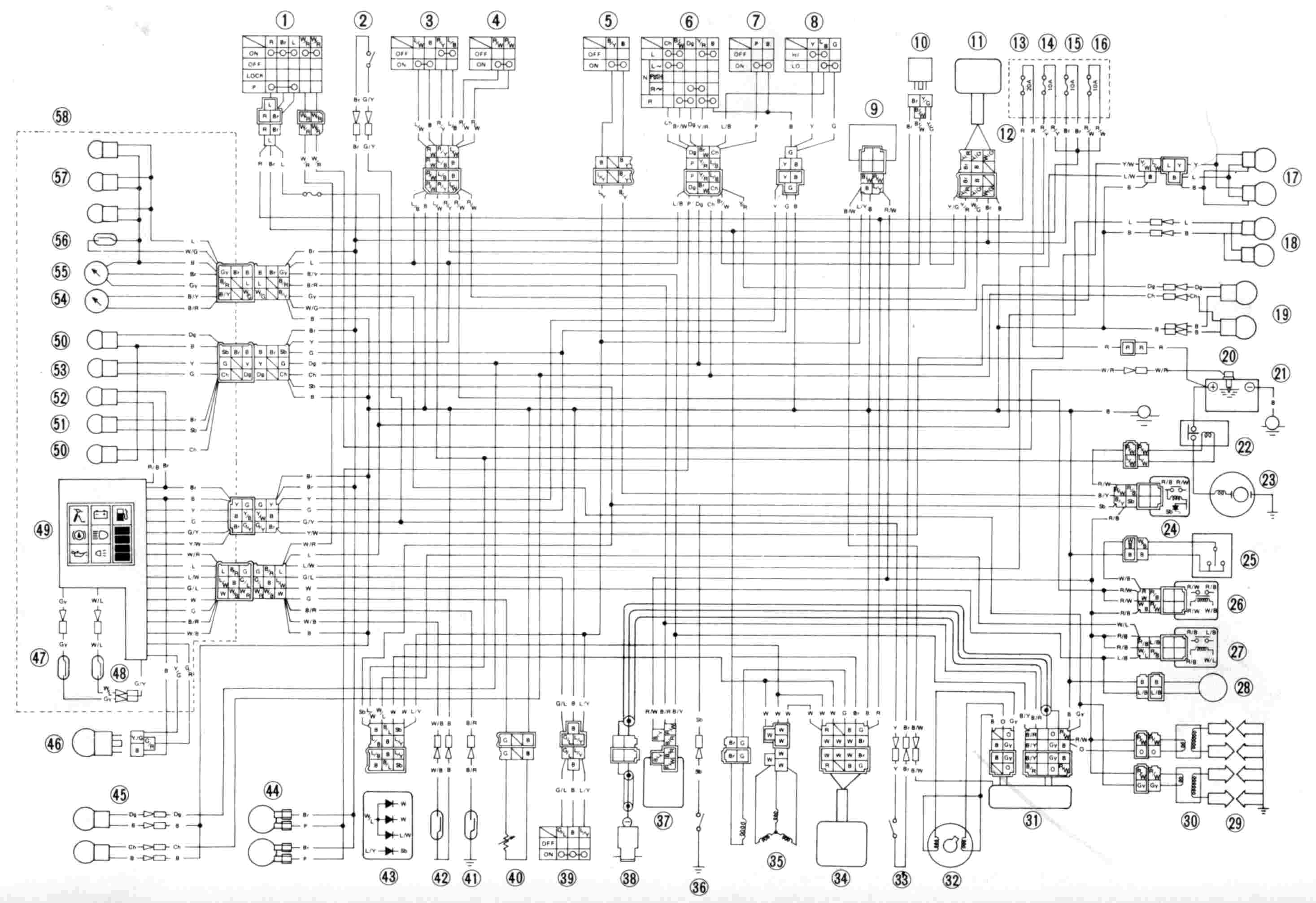
1. Main switch
2. Front brake switch
3. "START" switch
4. "ENGINE STOP" switch
5. Clutch switch
6. "TURN" switch
7. "HORN" switch
8. "LIGHT" (Dimmer) switch
9. Sidestand relay
10- Flasher relay
11. Cancelling unit
12. Fuse box
13. MAIN
14. HEAD
15. SIGNAL
16. IGNITION
17. Tail/brake light
18. License light
19. Rear flasher light
20. Battery sensor
21. Battery
22. Starter relay
23. Starter motor
24. Starter circuit cut-off relay
25. Emergency engine stop switch
26. Engine stop relay
27. Fuel pump relay
28. Fuel pump
29. Spark plug
30. Ignition coil
31. T.C.I, unit
32. Pick up coil
33. Rear brake switch
34. Rectifier/regulator
35. A.C. generator
36. Neutral switch
37. Boost pressure sensor
38. Knock sensor
39. Side stand switch
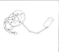
40. Fuel level sensor
41. Engine oil level sensor
42. Brake fluid level sensor
43. Diode
44. Horn
45. Front flasher light
46. Headlight
47. "CHECK" switch
48. "WARNING" control
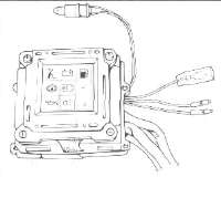
49. Computerized monitor
50. "TURN" indicator light
51. "NEUTRAL" indicator light
52. "WARNING" indicator light
53. "HIGH BEAM" indicator light
54. Boost pressure gauge
55. Tachometer
56. Sender
57. Meter light
58. Meter assembly
59. Sealed wire outer, inner
COLOR CODE
|
Br |
Brown |
Y |
Yellow |
L |
Blue |
R/W |
Red/White |
Y/B |
Yellow/Black |
Y/R |
Yellow/Red |
E |
Ground |
|
R |
Red |
Dg |
Dark Green |
P |
Pink |
L/W |
Blue/White |
Br/W |
Brown/White |
R/W |
Red /White |
B/R |
Black/Red |
|
W |
White |
Ch |
Chocolate |
O |
Orange |
L/B |
Blue/Red |
Y/G |
Yellow/Green |
L/R |
Blue/ Red |
Gy |
Gray |
|
B |
Black |
Sb |
Sky Blue |
G |
Green |
R/Y |
Red/Yellow |
W/G |
White/Green |
G/Y |
Green/Yellow |
B/Y |
Black/ Yellow |
Electric Starting System
Electric Starting System
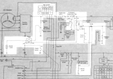
Above circuit diagram shows starter circuit in wiring diagram.
B. Starter Motor
1. Removal (see CHAPTER 3. "ENGINE DISASSEMBLY")
2. Inspection and repair
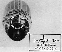
a. Check the outer surface of the commutator. If its surface is dirty, clean with # 600 grit sand paper.
b. The mica insulation between commutator segments should be 0.4 ~ 0.8 mm (0.02 ~ 0.03 in) below the segment level. If not, scrape to proper limits with appropriately shaped tool. (A hack saw blade can be ground to fit.)
NOTE:
Mica insulation of commutator must be undercut to ensure proper operation of commutator.
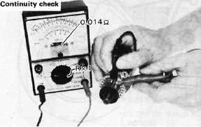
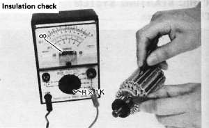
c. The starter's armature coil should be checked with an ohm meter for insulation breakdown (shorting to each other or to ground) and for continuity. Reference figure is given below.
Coil resistance: Armature coil: 0.014Ω at 20°C (68°F)
d. Check the front and rear cover bearings for damage. If damaged, the starter assembly must be replaced.
e. Check brush length. Replace brush if at, or near, limits.
Minimum brush length: 8.5 mm (0.33 in)
f. Check brush spring pressure. Compare it with a new spring. Replace the old spring if it is weak.
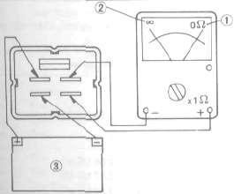
C. Starter Relay Switch
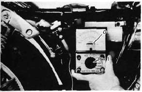
1. Inspection
a. Disconnect starter cable at the relay.
b. Connect pocket tester leads to the relay terminals (ohms x 1 scale).
c. Turn ignition to "ON" position, engine stop switch to "RUN" and change lever to "NEUTRAL".
d. Push the starter button. The relay should click once and the scale should read zero if it does not read zero, the relay must be replaced.
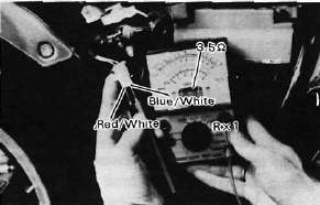
1. Battery lead wire (+)
2. Starter motor lead wire
e. If the relay does not click, check the wires from the starter button and from the battery (red/white, blue/white). Turn the ignition off. Use (ohms x 1) scale on tester. The resistance between these wires should be no more than 3.5Ω. If there is more resistance, the relay should be replaced.
Charging System
Charging System
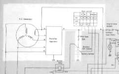
Above circuit diagram shows charging circuit in wiring diagram.
B. A.C. Generator
1. Checking method.
a. Connect D.C. voltmeter to the battery terminals.
b. Start engine.
c. Accelerate engine to approximately 2,000 r/min or more and check generated voltage.
Generated voltage: 14.5± 0.3V
d. If the indicated voltage cannot be reached, then perform the tests in step 2.
— CAUTION:---
Never disconnect wires from the battery while the generator is in operation. If the battery is disconnected, the voltage across the generator terminals will increase, damaging the semiconductors.
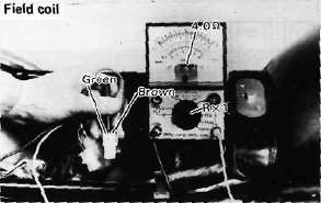
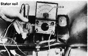
2. Resistance test of field coil and stator coil.
Check the resistance between terminals. If resistance is out of specification, coil is broken. Check the coil connections. If the coil connections are good, then the coil is broken inside and it should be replaced.
|
Field coil resistance: |
(Green-Brown) |
|
4.0Ω ± 10% at 20°C (68°F) |
|
|
Stator coil resistance |
(White-White) |
|
0.46Ω ± 10% at 20°C (68°F) |
|
C. Voltage Regulator
The IC Voltage Regulator is a small and, normally, very reliable component. Due to its construction, it is lightweight and free from the wear and misadjustment associated with mechanical voltage regulators. If the following inspection reveals that the regulator is faulty, it cannot be adjusted and must be replaced.
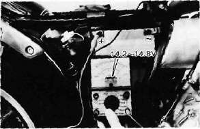
1. Checking IC Voltage Regulator
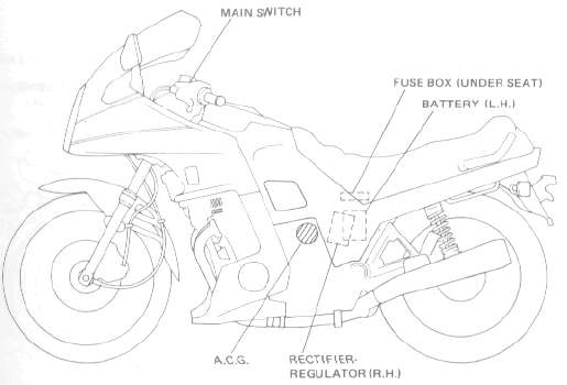
a. Remove the seat.
b. Remove the left side cover.
c. Measure the specific gravity of the battery fluid. If it is less than 1.260, remove the battery and recharge until it is more than 1.260. (See page 124 for charging procedures)
d. Check the battery terminals and couplers for looseness.
e. Connect two Yamaha pocket testers to the regulator coupler as illustrated.
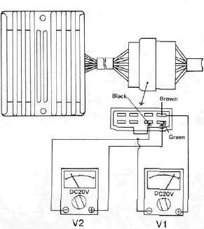
—CAUTION:
Be careful not to let the tester leads short circuit when connecting them to the regulator snap connector leads.
f. Turn the main switch on. Make sure that V2 is less than 1.8V.
NOTE:
Do not turn on lights or signals.
g. Make sure that V2 gradually increases up to 9 ~ 11V when the engine is started and its revolutions go up.
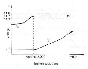
h. Make sure that Vi maintains the level of 14.2 ~ 14.8V even when engine revolutions increase.
i. If these levels are not maintained, the regulator is defective and must be replaced.
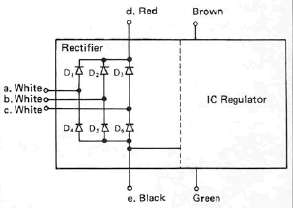
2. Checking the silicon rectifier a. Check the silicon rectifier as specified using the Yamaha pocket tester.
|
Checking element |
Pocket tester connecting point |
Good |
Replace (element shorted) |
Replace (element opened) |
|
|
(+) (red) |
(-) (black) |
||||
|
Di |
d |
a |
0 |
0 |
X |
|
a |
d |
X |
0 |
X |
|
|
D2 |
d |
b |
O |
0 |
X |
|
b |
d |
X |
0 |
X |
|
|
D3 |
d |
c |
0 |
0 |
X |
|
c |
d |
X |
0 |
X |
|
|
D4 |
a |
e |
0 |
0 |
X |
|
e |
a |
X |
0 |
X |
|
|
D5 |
b |
e |
0 |
0 |
X |
|
e |
b |
X |
o |
X |
|
|
D6 |
c |
e |
o |
0 |
X |
|
e |
c |
X |
0 |
X |
|
0 : Continuity
x : Discontinuity (∞)
b. Even if only one of the elements is broken, replace the entire assembly.
— CAUTION:---
The silicon rectifier can be damaged if subjected to overcharging. Special care should be taken to avoid a short circuit and/or incorrect connection of the positive and negative leads at the battery. Never connect the rectifier directly to the battery to make a continuity check.
Ignition System
Ignition System
Above circuit diagram shows only ignition circuit in wiring diagram.
B. Description
This model is equipped with a battery operated, fully transistorized breakerless ignition system. By using magnetic pick-up coils the need for contact breaker points is eliminated. This adds to the dependability of the system by eliminating frequent cleaning and adjustment of points and ignition timing. This T.C.I. (Transistor Control Ignition) unit incorporates an automatic advance circuit controlled by signals generated by the pick-up coil. This adds to the dependability of the system by eliminating the mechanical advancer. This T.C.I, system consists of two main units; a pick-up unit and ignitor unit.
C. Operation
The T.C.I, functions on the same principle as a conventional D.C. ignition system with the exception of using magnetic pick-up coils and a transistor control box (T.C.I.) in place of contact breaker points.
1. Pick-up unit
1. Pick-up coils
This unit consists of two pick-up coils and a magneto mounted on the crank-case (L.H.). When the reluctor (timing plate) projection passes the pick-up coil, the two signals are generated at the pickup coil and transmitted to the ignitor unit as a signal. The full ignition advance is determined by the width of the reluctor (timing plate) projection.
2- Ignitor unit
This unit has such functions of wave form, duty control, switching, electrical ignition advance, and etc. The ignition timing is advanced electrically using two signals from the pick-up coil. The duty control circuit is provided to control the on time period of the primary ignition current to reduce the electrical consumption. This unit also incorporates a protective circuit for the ignition coil. If the ignition switch is turned on and the crankshaft is not turned, the protective circuit stops current flow to the primary coil within a few seconds. When the crankshaft is turned over, the current is turned on again by the signals generated by the pick-up coils.
CAUTION:
Do not run the engine without any spark plug cap(s) in place. Due to the high secondary voltage, it is possible to damage the internal insulation of the secondary coil.
D. Troubleshooting/Inspection
1. The entire ignition system can be checked for misfire and weak spark using the Electro Tester. If the ignition system will fire across a sufficient gap, the entire ignition system can be considered good. If not, proceed with individual component tests until the problem is found.
a. Warm up engine thoroughly so that all electrical components are at operating temperature.
b. Stop the engine and connect the tester as shown.
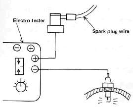
c. Start the engine and increase the spark gap until misfire occurs. (Test at various r/min between idle and red line.)
Minimum spark gap: 6 mm (0.24 in)
CAUTION:
Do not run engine in neutral above 6,000 r/min for more than 1 or 2 seconds.
2. If the ignition system should become inoperative, the following troubleshooting aids will be useful.
| Check entire ignition for connections |
---------------> Poor connection |
Correct |
|
▼ OK ▼ |
||
| Check battery for voltage and specific gravity |
---------------> Low voltage & specific gravity |
Recharge battery |
|
▼ OK ▼ |
||
| Check fuse and fuse connections | ---------------> Weak connection or open circuit |
Correct connection or replace fuse |
|
▼ OK ▼ |
||
| Check resistance of ignition coil {primary and secondary) Primary: 2.5 Ω ± 10% at 20°C (68°F) Secondary: 11KΩ ± 20% at 20°C(68 F) |
---------------> If other than specified |
Replace ignition coil |
|
▼ OK ▼ |
||
| Check pick-up coils for resistance Pick-up coil: 700 Ω ± 20% at 20°C (68°F) |
---------------> If other than specified |
Replace pick-up coil assembly |
|
▼ OK ▼ |
||
| TCI unit is faulty, replace unit |
3. Ignition coil
a. Coil spark gap test.
1) Remove the fuel tank and disconnect the ignition coil from wire harness and spark plugs.
2) Connect the Electro Tester as shown.
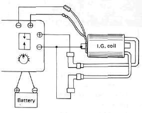
3) Connect fully charged battery to tester.
4) Turn on spark gap switch and the increase gap to maximum unless misfire occurs first.
Minimum spark gap: 6 mm (0.24 in)
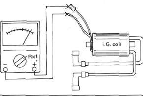
b. Direct current resistance test. Use a pocket tester or equivalent ohmmeter to determine resistance and continuity of primary and secondary coil windings.
Standard value: Primary coil resistance:
2.5Ω ± 10% at 20°C (68°F)
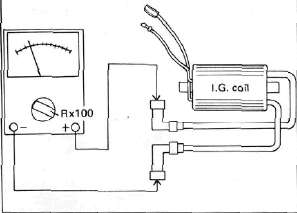
Secondary coil resistance:
11 KΩ ± 20% at 20% (68°F)
Primary coil check
Secondary coil check
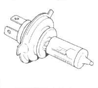
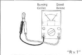
4. Spark plug
The life of a spark plug and its discoloring vary according to the habits of the rider. At each periodic inspection, replace burned or fouled plugs with new ones of the specified type. It is actually economical to install new plugs often since it will tend to keep the engine in good condition and prevent excessive fuel consumption.
a. Inspection
1) Inspect and clean the spark plug every 4,000 km (2,500 mi) and replace after initial 13,000 km (8,000 mi).
2) Clean the electrodes of carbon and adjust the electrode gap to the specification.
b. Installation
Be sure to use the proper reach, type and electrode gap plug(s) as a replacement to
avoid overheating, fouling or piston damage.
Type:
BP7ES (NGK) or W22EP (ND) Electrode gap:
0.7 - 0.8 mm (0.028 - 0.031 in) Tightening torque:
2.0 m-kg (14.5 ft-lb)
Lighting System
Lighting System
Above circuit diagram shows only signal circuit in wiring diagram.
B. Lighting Tests and Checks
The battery provides power for operation of the headlight, taillight, and meter lights. If none of the above operates, always check battery voltage before proceeding further. Low battery voltage indicates either a faulty battery, low battery water, or a defective charging system. See page 113 "CHARGING SYSTEM" for checks of battery and charging system. Also check fuse condition. Replace any "open" fuses. There are individual fuses for various circuits (see complete Circuit Diagram).
NOTE:
Check the headlight bulb first before performing the following check.
1. Headlight check NOTE:
When the engine is started, the headlight and meter lights come on automatically and the lights stay on until the main switch is turned to "OFF" even if the engine stalls.
|
HEADLIGHT DOES NOT COME ON WHEN ENGINE IS RUNNING |
Check for voltage on "W" wire to safety relay |
-----------> |
Check AC generator, diode, or wiring circuit |
▼ ▼ |
Check for battery voltage (12V) on "R/Y" wire to headlight relay |
-----------> No voltage |
Check fuse "Head or wiring circuit |
▼ Voltage OK ▼ |
Check for battery voltage (12V) on "L/B" wire from headlight relay |
-----------> No voltage |
Replace headlight relay |
|
HIGH BEAM AND/OR LOW BEAM DO NOT LIGHT |
Check for battery voltage at dimmer switch terminal |
-----------> |
Dimmer switch defective |
▼ Voltage OK ▼ |
Check for battery voltage at headlight high beam or low beam terminal |
-----------> |
Open or poor connection between headlight and dimmer switch terminal |
▼ Voltage OK ▼ |
Poor ground or poor connection of headlight wiring |
2. Taillight does not work:
a. Check bulbb
b. Check for 12V on blue wire.
c. Check for ground on black wire to tail/brake light and/or license light assembly.
Signals
SignalsSIGNAL SYSTEM
A. Circuit Diagram
Above circuit diagram shows only signal circuit in wiring diagram.
B. Signal System Tests and Checks
The battery provides power for operation of the horn, brake light, indicator lights and flasher light. If none of the above operates, always check battery voltage before proceeding further. Low battery voltage indicates either a faulty battery, low battery water, or a defective charging system. See page 113 "CHARGING SYSTEM" for checks of battery and charging system. Also check fuse condition. Replace any "open" fuses. There are individual fuses for various circuits (see complete Circuit Diagram).
1. Horn does not work:
a. Check for 12V on brown wire to horn.
b. Check for good grounding of horn (pink wire) when horn button is pressed.
2. Brake light does not work:
a. Check bulb.
b. Check for 12V on yellow wire to brake light.
c. Check for 12V on brown wire to each brake light switch (front brake and rear brake switches).
3. Flasher light(s) do not work:
a. Check bulb.
b. Right circuit:
1) Check for 12V on dark green wire to light.
2) Check for ground on black wire to light assembly.
c. Left circuit:
1) Check for 12V on dark brown wire to light.
2) Check for ground on black wire to light assembly.
d. Right and left circuits do not work:
1) Check for 12V on brown/white wire to flasher switch on left handlebar.
2) Check for 12V on brown wire to flasher relay.
3) Replace flasher relay.
4) Replace flasher switch.
e. Check flasher self-canceling system. (Refer to flasher self-canceling system.)
4. Neutral light does not work:
a. Check bulb.
b. Check for 12V on sky blue wire to neutral switch.
c. Replace neutral switch.
6. Oil level warning light does not work:
a. Connect oil level switch (black/red wire) to ground. If light comes on, check for proper oil level.
b. If oil level is correct, replace oil level switch.
C. Self-Canceling Flasher System
1. Description:
The self-canceling flasher system turns off the turn signal after a period of time or distance involved in turning or changing lanes. Generally, the signal will cancel after either 10 seconds, or 150 meters (490 feet), whichever is greater. At very low speed, the function is determined by distance; at high speed, especially when changing speeds the canceling determination is a combination of both times and distance.
2. Operation:
The handlebar switch has three positions: L (left), OFF, and R (right). The switch lever will return to the "OFF" position after being pushed to L or R, but the signal will function. By pushing the lever in, the signal may be cancelled manually.
3. Inspection
If the flasher self-canceling system should become inoperative, proceed as follows:
a. Pull of the 6-pin connector from the flasher canceling unit, and operate the handlebar switch, if the signal operates normally in L, R, and OFF, the following are in good condition.
1) Flasher unit
2) Bulb
3) Lighting circuit
4) Handlebar switch light circuit
If (1) through (4) are in good condition, the following may be faulty:
1) Flasher canceling unit.
2) Handlebar switch reset circuit.
3) Speedometer sensor circuit.
b. Pull off the 6-pin connector from the flasher canceling unit, and connect a tester (ohms x 100 range) across the white/green and the black lead wires on the wire harness side. Turn the speedometer shaft. If the tester needle swing back and forth between 0 and ∞, the speedometer sensor circuit is in good condition. If not, the sensor to wire harness may be inoperative.
c. Pull the 6-pin connector from the flasher canceling unit. Check if there is continuity between the yellow/red lead wire on the wire harness side and the chassis.
Flasher switch OFF: ∞
Flasher switch L or R: 0 ohms
If the tester needle does not swing as indicated above, check the handlebar switch circuit and wire harness.
d. If no defect is found with the above three check-ups and the flasher canceling system is still inoperative, replace the flasher canceling unit.
e. If the signal flashes only when the handlebar switch lever is turned to L or R and it turns off immediately when the handlebar switch lever returns to center, replace the flasher canceling unit.
D. Switches
Switches may be checked for continuity with a pocket tester on the "ohm x 1" position. 1. Main switch
|
Switch Position |
Wire Color |
||
|
R |
Br |
L/Y |
|
|
ON |
0---- |
--0-- |
----0 |
|
OFF |
|
|
|
|
LOCK |
|
|
|
|
P (parking) |
0---- |
------ | ----0 |
2. "ENGINE STOP" Switch
|
Switch |
Wire Color |
|
|
Position |
R/W |
R/W |
|
RUN |
0---- |
----0 |
|
OFF |
|
|
3. "START" switch
|
Button Position |
Wire Color |
|
|
L/W |
Ground |
|
|
PUSH |
O----- |
----O |
|
OFF |
|
|
4. "LIGHTS" (Dimmer) switch
|
Switch Position |
Wire Color |
|||||
|
Y |
L/Y |
G |
G |
L/G |
Y/B |
|
|
HI |
0--- | --O |
|
0--- |
--O |
|
|
LO |
|
0--- |
--O |
|
O---- |
--O |
5. "TURN" switch
|
Switch Position |
Wire Color |
||||
|
Ch |
Br/W |
Dg |
Y/n |
Ground |
|
|
L |
0--- |
--O |
|
0--- |
--O |
|
L > N |
0--- |
--O |
|
|
|
|
N > Push |
|
|
|
|
|
|
R > N |
|
O--- |
--O |
|
|
|
R |
|
O--- |
--O |
0--- |
--O |
6. "HORN" Switch
|
Button Position |
Wire Color |
|
|
P |
Ground |
|
|
PUSH |
O--- |
------O |
|
OFF |
|
|
E. Battery
1. Checking
If the battery shows the following defects, it should be replaced.
a. The battery voltage will not rise to a specific value or no gassing occurs in any cell even after many hours of charging.
b. Sulfation of one or more cells is indicated by the plates turning white or an accumulation of material in the bottom of the cell.
c. Specific gravity readings after a long slow charge indicate a cell to be lower than any others.
d. Warpage or buckling of plates or insulators is evident.
WARNING:
Battery fluid is poisonous and dangerous, causing severe burns, etc. Contains sulfuric acid. Avoid contact with skin, eyes or clothing.
Antidote:
EXTERNAL-FLUSH with water.
INTERNAL-Drink large quantities of water or milk. Follow with milk of magnesia, beaten egg or vegetable oil. Call physician immediately.
Eyes: Flush with water for 15 minutes and get prompt medical attention.
Batteries produce explosive gases. Keep sparks, flame, cigarettes, etc., away. Ventilate when charging or using in enclosed space. Always shield eyes when working near batteries.
KEEP OUT OF REACH OF CHILDREN.
2. The service life of a battery is usually 2 to 3 years, but lack of care as described below will shorten the life of the battery.
a. Negligence in keeping battery topped off with distilled water.
b. Battery being left discharged.
c. Over-charging with heavy charge.
d. Freezing.
e. Filling with water or sulfuric acid containing impurities.
f. Improper charging voltage or current on new battery.
3. If the motorcycle is not to be used for a long time, remove the battery and have it stored. The following instructions should be observed:
a. Recharge the battery periodically.
b. Store the battery in a cool, dry place.
c. Recharge the battery before reinstallation.
|
Battery |
12N12A-4A-1 |
|
Electrolyte |
Specific gravity: 1.280 |
|
Initial charging current |
1.2 amp for 10 hours (new battery) |
|
Recharging current |
10 hours (or until specific gravity reaches 1.280) |
|
Refill fluid |
Distilled water (to maximum level line) |
|
Refill period |
Check once per month (or more often, required) |
Computerized Monitoring System
Computerized Monitoring SystemCMS Operation
CMS OperationGENERAL
Operation
NOTE: Before starting out on the road, check the motorcycle conditions using computerized monitor system.
1. When the main switch is turned on, all seven liquid crystal displays (LCDs) come on, with the fuel display indicating the amount of fuel in the tank.
2. When the engine is started, the system begins its scan of the motorcycle conditions. From top to bottom all the LCDs flash on and then off in sequence. If any one condition is found improper or inadequate, the red warning light will begin flashing and the LCD for the area in question will remain displayed.
3. Warning light operation can be controlled by the warning control switch. If the control switch is pushed once, the warning light glow will change from a flashing to a steady one. If pushed again, the glow will go out completely. Still another push on the switch brings back the warning light operation all over again.
NOTE:
1. This switch operates only when a malfunction is displayed on an LCD.
2. Even if the warning light is made to glow; steady or to go out, it will begin flashing on with another malfunction.
4. The entire monitoring system condition can be checked by pushing the check switch. The system will scan through the seven areas in sequence, just as when the engine was first started, to assure the rider that the system is functioning properly.
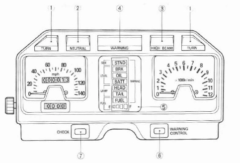
1. Turn indicator light
2. Neutral indicator light
3. High beam indicator light
4. Warning light
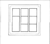
5. Display panel
6. Warning control switch
7. Check switch
(XJ 750R panel shown)
| CMS Operation Flow Chart | ||||
| All circuits OFF | ||||
| ▼ | ||||
| Main switch ON | ||||
| ▼ | ||||
| Red warning light and all LCD readouts stay ON for self check. | ||||
| ▼ | ||||
| Engine Starts | ||||
|
|
▼ | |||
| ► | The system automatically cycles once. (CMS monitors all functions during machine operation.) |
► | Red warning light FLASHES and a particular LCD readout stays ON | ◄ |
| ▲ | ▼ | ▼ | ▲ | |
| ▲ | If all LCD readouts are OFF | ◄ |
Displayed function must be corrected immediately. |
▲ |
| ▲ | ▼ | ▼ | ▲ | |
| ▲ |
Monitored functions are in good condition. |
Push Warning control switch | ▲ | |
| ▲ | ▼ | ▼ | ▲ | |
| ▲ | Press Check switch |
Red warning light stops flashing and stays on. LCD readout continues to stay ON. |
▲ | |
| ▲ | ◄ | ▼ | ▲ | |
| Push Warning control switch | ▲ | |||
| ▼ | ▲ | |||
| Main switch OFF |
Red warning light goes OFF |
▲ | ||
| ▼ | ▼ | ▲ | ||
| Operation stops. | Push Warning control switch | ▲ | ||
Display Panel (XJ650L Turbo panel shown)
Sidestand

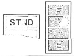
This indicator is displayed when the sidestand is extended. Be sure to retract it before starting out on the road.
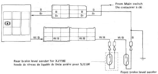
Brake fluid level

This indicator is displayed when the brake fluid level is below specification in the front brake master cylinder.
Do not run the motorcycle with a low brake fluid level for a long time or at high speeds.
Engine oil level

This indicator is displayed when the engine oil level is low. If it remains displayed or keeps flickering while riding, add engine oil.
Do not run the motorcycle with a low engine oil level for a long time or at high speeds.
Battery fluid level

This indicator is displayed when the battery fluid level is low. If it remains displayed, add distilled water.
CAUTION:
Continuous riding with a low battery fluid level will damage the battery.
Headlight bulb

This indicator is displayed when the headlight bulb is burned out. If it remains displayed, have it replaced and correctly adjusted.
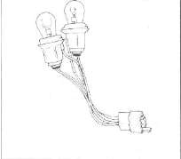
Tail/brake light bulbs

This indicator is displayed when the taillight and/or brake light bulbs are burned out. If it remains displayed, have it replaced.
Fuel amount

This indicator is displayed when the fuel level is low. If it remains displayed or keeps flickering while riding, add fuel.
This indicator is displayed the amount of fuel in the tank. If the four blocks are displayed, the fuel is full.
IMPORTANT NOTICE Headlight, Tail/brake lights
* Bulbs of wattage other than specified mustn't be used.
Extra electric accessories mustn't be connected to the each light circuit.
Reason:
1. CMS calculates the amount of current flow in these circuits.
2. Excessive current flow in these circuits may damage the control units, or
3. LCD panel may not display failure. Battery Sender
* Clean battery sender terminal occasionally. (Approximetry every 5,000 km)
Reason: The terminal, though made of lead, can be corroded on its surface, resulting in malfunction.
Other Senders
* Do not modify or add any electrical load to any sender.
Reason: Any modification may result in CMS malfunction.
Handling
* The instrument panel mustn't be subjected to any water splashes or steam from underneath.
* The display panel mustn't be pressed hard or given any shock.
* A magnet or other magnetized objects mustn't be put near the display panel.
CMS Components
CMS ComponentsSender locations
XJ650
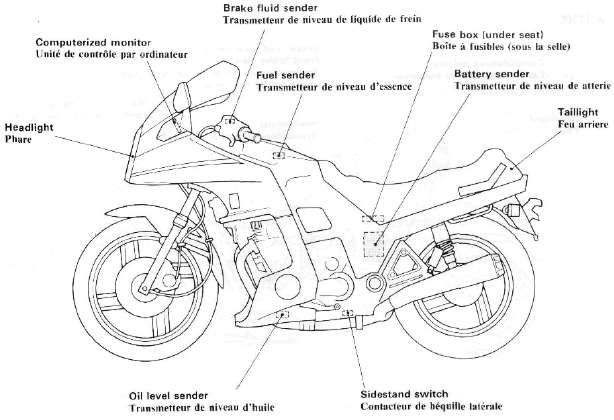
System Components
|
Sidestand switch |
Brake fluid level sender |
Engine oil level sender |
|
|
|
|
|
Battery fluid level sender |
Headlight bulb |
|
|
Tail/Brake light bulb |
||
|
|
|
|
|
Fuel level sender |
Computerized monitor |
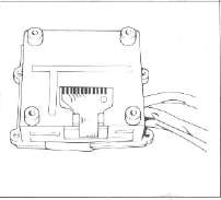
LCD panel |
|
|
|
|
|
Computer unit |
"Check" switch |
"Warning" switch |
|
|
|
|
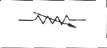
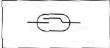
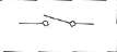
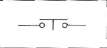
Symbol Identification
|
|
Conductor |
|
Bulb (single filament) |
|
|
|
Crossing conductor (not joined) |
|
Bulb (Double filament) |
|
|
|
Conductors joined |
|
Wire connector |
|
|
|
Ground (earth) |
|
Diode |
|
|
|
Resistor (adjustable) |
|
Sender |
|
|
|
Switch |
|
|
Power input |
|
|
Switch
|
|
|
Power output |
|
|
Fuse |
|
Battery |
|


Color Code
|
Br |
Brown |
Gy |
Gray |
|
B |
Black |
G/R |
Green/ Red |
|
L |
Blue |
G/L |
Green/ Blue |
|
W |
White |
G/Y |
Green/Yellow |
|
Y |
Yellow |
L/W |
Blue/ White |
|
G |
Green |
Y/W |
Yellow/ White |
|
Y/G |
Yellow/ Green |
B/R |
Black/ Red |
|
W/R |
White/Red |
G/W |
Green/ White |
|
W/B |
White/ Black |
W/L |
White/Blue |
|
R/B |
Red/Black |
Y/B |
Yellow/Black |
NOTES ON TROUBLESHOOTING
Before checking the computerized monitor, check the following points:
Battery: Be sure to use a fully-charged battery for troubleshooting.
Motorcycle: The motorcycle to be inspected must be of standard specification (not modified after shipped from the factory).
1. No optional parts for users are fitted to the motorcycle. (Decoration light, etc.)
2. No modification is made to any part of the motorcycle. (Change in electrical circuits, etc.)
3. The level displayed on each monitor is correct, (the fuel, engine oil, brake fluid, and battery fluid levels are correct.)
4. All light bulbs are in good condition.
Tester: Use a Yamaha Pocket tester for checking of electrical parts.
CMS Monitor Troubleshooting
CMS Monitor TroubleshootingProblem: THE COMPUTERIZED MONITOR DOES NOT COME ON WITH THE MAIN SWITCH TURNED ON.
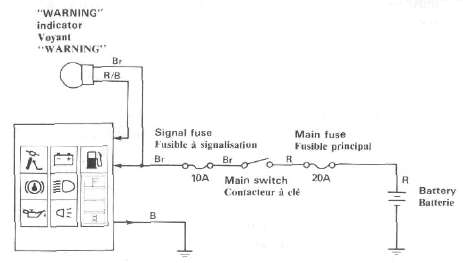
| Operate the horn and flashers to check the charged state of the battery. | Bad ► |
• Recharge the battery. • Check the fuse and main switch. |
| Good | ||
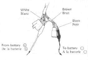
Apply 12 volts to the brown lead on the monitor side through the 6-P coupler in the headlight body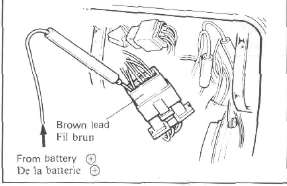 |
Comes on ► |
• Grounding is poor. (Check the black lead.) |
| Does not come on ▼ | ||
Ground the black lead of the coupler to the engine while applying 12 volts.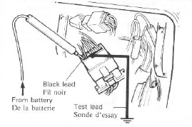 |
||
|
Does not come on▼ |
||
|
• LCD is faulty. |
Problem: THE MONITOR COMES ON, BUT THE "WARNING" INDICATOR DOES NOT.
|
|
|
|
|
Check the WARNING indicator bulb. |
Burnt out |
• Replace. |
|
Good ▼ |
|
|
|
• CMS is faulty. |
|
|
Problem: WHEN THE ENGINE HAS STARTED, THE MONITOR DOES NOT AUTO-SCAN.
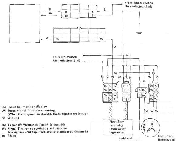
|
*Main switch is ON. Disconnect the W lead of the 9-P coupler (on the monitor side) in the headlight body. Apply DC 12V to the W lead.
|
Does not scan ► |
• CMS is faulty. |
| Scans ▼ | ||
|
• AC generator is faulty. |
Problem: THE MONITOR DOES NOT SCAN WITH THE CHECK SWITCH PUSHED.
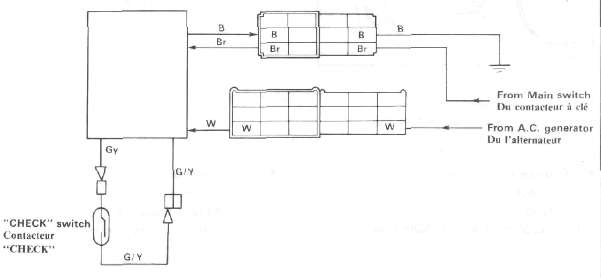
| With the main switch turned on, all monitors come on, and when the engine has started, auto-scan starts. | Does not operate ► |
• See the "Troubleshooting" in the previous page. |
| Operates ▼ | ||
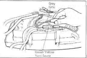
| Disconnect the connector adjacent to the check switch on the back of meter assembly.
Apply 12 volts to both the Brown and White leads, and ground the Black lead. Next, bring the Grey lead to directly contact the Green/ Yellow lead once, and separate them. |
Operates ► |
• Check switch is faulty. |
| Does not operate ▼ | ||
| • CMS is faulty. |
Problem: WHEN THE WARNING CONTROL SWITCH IS PUSHED, THE DISPLAY DOES NOT CHANGE. (DURING THE DISPLAY OF TROUBLE)
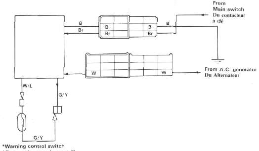
| Disconnect the connector adjacent to the "warning control" switch on the back of the meter assembly
Bring W/L to contact with G/Y, then disconnect it. By repeating this operation, check to see that the light switches from one to another while flashing.
|
Switches ► |
• Warning control switch is faulty. |
| Does not change ▼ | ||
| • CMS is faulty. |
CMS Sensors Troubleshooting
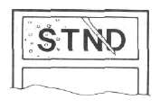
CMS Sensors TroubleshootingSIDESTAND MONITOR
|
*Main switch is ON. Disconnect the 3-P coupler on the side-stand side.
|
Operates as specified in a. and b. ► |
• Side-stand switch is faulty.
|
| Measure voltage between G/L and B on harness side. | ||
| Less than 12V ▼ | ||
Disconnect the G/L lead from the 9-P coupler (on the monitor side) in the headlight body, and ground it.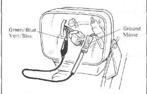 |
Operates ► |
• Green/blue lead is broken. |
| Does not operate ▼ | ||
|
• CMS is faulty. |
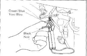
NOTE: If the side stand monitor comes on with the main switch turned on, CMS is faulty.
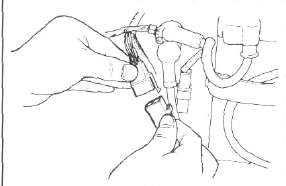
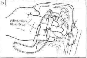
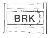
BRAKE FLUID MONITOR
|
*Main switch is ON. Disconnect the connector of white/black lead |
|
|
|
Ground the W/B female connector with a jumper wire |
Operates |
• Brake level sender is faulty.
|
|
Does not operate ▼ |
|
|
|
Disconnect the W/B lead of the 9-P coupler (on the monitor side) in the headlight body, and ground it. |
Operates |
• White/Black lead is broken. |
| Does not operate ▼ | ||
|
• CMS is faulty. |

NOTE: If the "BRK" monitor comes on with the main switch turned on, CMS is faulty.
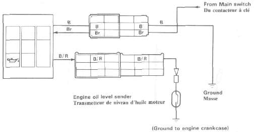
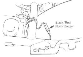
ENGINE OIL MONITOR
|
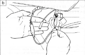
*Main switch is ON. Disconnect the connector adjacent to the oil level sensor located under the crankcase.
|
Operates as specified in a. and b. ► |
• Engine oil level sender is faulty.
Note: When installing the engine oil level sender, be sure to use a hand wrench to tighten the bolt. If it is tightened by using a compressed air driven tool, sender malfunctions may occur. |
| Does not operate ▼ | ||
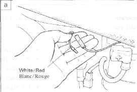
Disconnect the B/ R lead of the 9-P coupler (on the monitor side) in the headlight body, and ground it.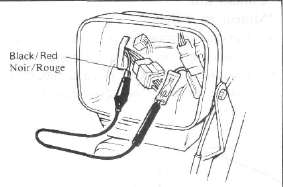 |
Operates ► |
• Black/red lead is broken. |
| Does not operate ▼ | ||
|
• CMS is faulty. |
NOTE: If the oil level monitor comes on with the main switch turned on, CMS is faulty.
BATTERY MONITOR
|
*Main switch is ON. Disconnect the connector adjacent to the battery sensor.
a. When disconnected: "BATT" monitor comes on.
b. When 12V is applied to the wire harness side of W/R lead: "BATT" monitor goes off. |
Operates as specified in a. and b. ► |
• Battery fluid level sender is faulty.
NOTE: Polish the battery sender terminals with sandpaper, check the sender again. |
| Does not operate ▼ | ||
|
Disconnect the 2-P connector of the main switch in the headlight body.
a. When disconnected: "BATT" monitor comes on.
|
Operate as specified in a. and b. ► |
• Main switch is faulty.
|
| Does not operate ▼ | ||
|
Disconnect the W/R lead of the 9-P coupler (on the monitor side) in the headlight body.
b. When 12V is applied to the monitor side of W/R lead: "BATT" monitor goes off.
|
Operates as specified in a. and b. ► |
• White/Red lead is broken. (Main switch to 9-P coupler) |
| Does not operate ▼ | ||
| • CMS is faulty. |
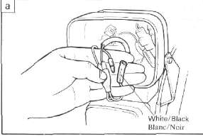
FUEL MONITOR
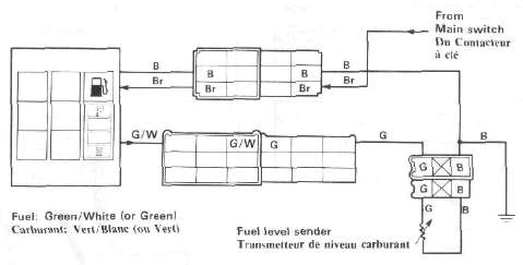
'Fuel tank is full.
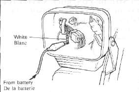
| *Main switch is ON. *Engine running Disconnect the 3-P coupler on the fuel tank side. a. When disconnected: Fuel monitor comes on but the display of the remaining amount of fuel goes off.
b. When green/white lead is grounded: The remaining amount (4 blocks) of fuel is displayed, but the fuel monitor goes off.
|
Operates as specified in a. and b. ► |
• Fuel level sender is faulty.
|
| Does not operate ▼ | ||
|
Disconnect the G/W lead at the 9-P coupler (on the monitor side) in the headlight body, and ground it.
|
Operates ► |
• Green/White lead is broken. |
| Does not operate ▼ | ||
|
• CMS is faulty. |
NOTE: If both monitor and blocks are displayed with the main switch turned on, CMS is faulty.
Troubleshooting Headlight, Brakelight, Taillight issues and other CMS Troubles
Troubleshooting Headlight, Brakelight, Taillight issues and other CMS TroublesProblem: HEADLIGHT DOES NOT COME ON. (MONITOR DOES NOT LIGHT.)
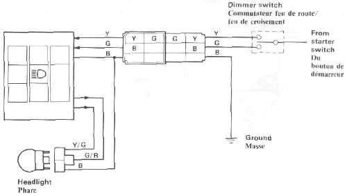
Light lead connections:
HI: Yellow to Yellow/Green (or Yellow/Red)
Lo: Green to Green/Red
NOTE: On the XJ750, no lights will come on before the engine starts.
|
Disconnect the 3-P coupler (for headlight) in the headlight body, and check voltage. |
12V ► |
Headlight bulb is burnt out. |
| Less than 12V ▼ | ||
| Measure input voltage on the wire harness side through the 6-P coupler in the headlight body. Hi: Yellow to Ground Lo: Green to Ground 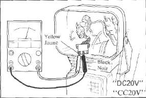 • • |
Reads 12V ► |
• CMS is faulty |
| Less than 12V ▼ | ||
|
• Dimmer switch Check the condition of these parts according to the electrical section of the service manual. |
Problem: HEADLIGHT COMES ON AND MONITOR WILL NOT GO OFF.
• CMS is faulty.
• LCD is faulty.
• Connector is faulty.
NOTE: If the monitor (HEAD) comes on with the main switch turned on, both LCD and connector are in good condition. Replace CMS.
Problem: THE HEADLIGHT BULB IS NOT BURNT OUT, BUT THE MONITOR COMES ON.
• Yellow/Green lead is broken.
• Green/Red lead is broken.
• Black lead is broken.
• Connector is loose.
TAIL/BRAKE LIGHT DOES NOT COME ON. (MONITOR DOES NOT COME ON.)
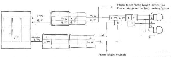
Light lead connections:
Tail: Blue-Blue/White
Brake: Green/Yellow- Yellow/White (or Yellow/Black)
|
Disconnect the 3-P coupler of the taillight, and measure voltage. |
12V ► |
• Burnt taillight bulb
|
|
Less than 12V ▼ |
||
|
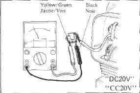
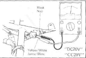
Disconnect the Y/W and L/W leads from the monitor side of the 6-P and 9-P couplers, and check voltage. |
12V |
• Broken Yellow/White lead
|
|
Less than 12V ▼ |
|
|
| Measure voltage of the L lead and G/Y lead on the wire harness side. Tail: Blue lead from Main switch Brake: Green/Yellow lead from brake switches 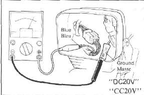 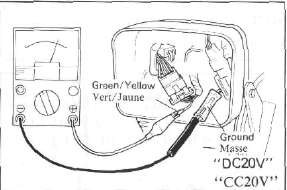 |
12V ► |
• CMS is faulty. |
| Less than 12V ▼ | ||
|
• Brake: Check the brake switch and leads. |
|
|
EXAMPLES OF OTHER TROUBLES
The computerized monitor system may malfunction under the following conditions, though it is in good condition. The term "malfunction" means an erratic change in the display when the computerized monitor is not operated.
1. The battery is in a state of extremely low voltage. The computerized monitor system is so designed that it operates normally when a specific voltage is input. Therefore, if the battery has almost run down or sulfation, the system may malfunction.
2. The computerized monitor system is interfered by radio noise. The system has a protective device against radio noise, but some special radio noise may cause the system to malfunction.
Radio noise can be produced in the following cases:
a. When spark plugs without resistor are used on an engine for which spark plugs with built-in resistor should be used.
b. When a special horn is used.
EXAMPLES OF ERRATIC LC. DISPLAYS
If any one of the following symptoms appears, the L.C. display is considered to be faulty.
1. Part of the L.C. display is chipped off.
2. The deflecting plate has scratches or cavities.
3. Glass is cracked or chipped,
4. Contrast is uneven on the same display.
CMS Wiring Diagram
CMS Wiring DiagramXJ650
Ignition Control System
Ignition Control SystemThis motorcycle is equipped with the conventional transistor advance system as well as a semi conductor controlled boost sensor and a knock sensor. These combine to produce the optimum ignition timing according to engine conditions (i.e., engine speed, load, knocking, etc.).
Ignition system block diagram
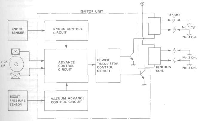
VACUUM ADVANCE CONTROL SYSTEM
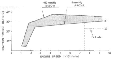
Generally speaking, in a 4-stroke motorcycle, the knocking zone varies with engine load.
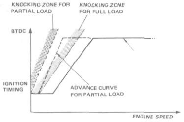
In an advance system concerned only with engine speed, the ignition advance is set as indicated by the heavy broken line (-------------}, whereas in the advance system assisted by the sensing of the engine load conditions, the optimum ignition can be obtained by setting the timing as indicated by the lighter broken line (-------------). This is the case especially under partial-load conditions.
Engine load conditions are monitored by a semiconductor boost sensor and computed in the electronic circuit for the control of ignition timing. The absence of moving parts for this ignition-timing system contributes to the longer life, smaller size, and lighter weight of the entire system.
KNOCK SENSOR
The knock sensor senses the high-frequency vibrations developed by the engine and, as soon as this takes place, this knock sensing system retards the ignition timing gradually so that knocking can be suppressed.
When there is no knocking for a certain period of time, this system functions to advance the ignition timing very gradually, until knocking is about to occur. This sensor feeds back the vibrations from the knocking engine and thereby controls the ignition timing so it is always set at an advanced position, but just before knocking would occur.

In this way, this knock-control system makes it possible to deal with constantly varying operating conditions, thereby supplying the constant and optimum ignition timing and spark.
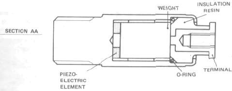
This sensor which is mounted between #2 and #3 cylinders on the exhaust side, employs a combined piezoelectric element and terminal place. This unit senses high-frequency oscillations caused by engine knocking. The oscillations are a form of pressure, and this pressure generates electrical voltage in the piezo element. The generated voltage is carried to the ignitor unit, and this signal retards the timing, preventing the engine from knocking.
Fail-safe functions
If the knock sensor fails because of a lead failure, short-circuit, couple disconnection, or sensor
damage, the ignitor unit automatically retards ignition timing from the advanced setting.
(1} If the pressure sensor is disconnected, the ignition unit automatically retards the ignition
timing to the curve (1) shown in the illustration. (2) If the knock sensor output is zero, the ignitor unit automatically retards 5 ± 1.5° from the
advanced setting, the safest setting over 7,500 rpm.
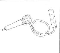
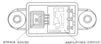
PRESSURE SENSOR
This boost sensor unit consists of a semiconductor strain gauge and an amplifying circuit. Pressure to the carb manifold {venturi portion) is sensed by the strain gauge and amplified in the circuit connected with this gauge. The amplified pressure signals are than transmitted to the ignition system for the control of ignition timing advance.
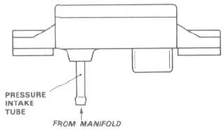
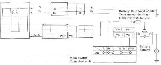
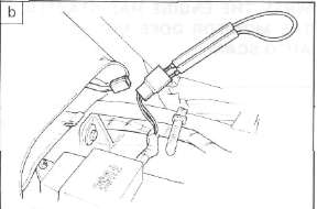
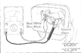
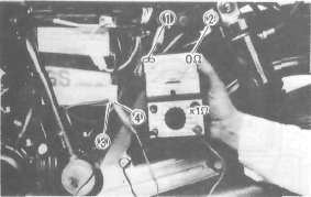
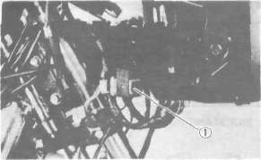
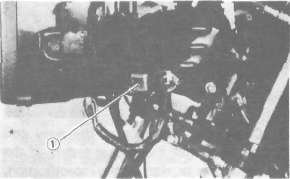
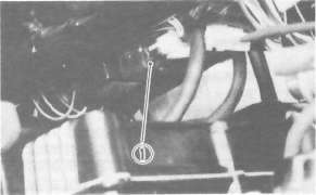
PRESSURE SENSOR INSPECTION (OFF-FRAME)
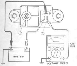
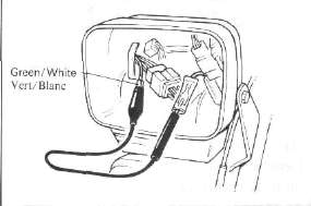
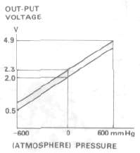
Open the pressure intake tube 1 to the atmosphere, and check the voltage between the output terminal 2 and the ground. See the following picture.
Output voltage: About 2.0 DC. volt
1. Remove the seat.
2. Remove the side panels as one piece.
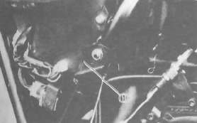
3. Remove the stay 1.
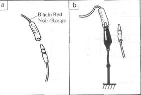
4. Pull out the TCI unit connecter and connect a Yamaha Pocket Tester.
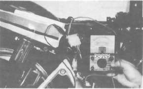
+ lead-Black/Red - lead -Black/Yellow
5. Turn the main switch key to ON; or connect the battery
+ lead to R/W and - lead to ground.
6. Read the tester. If the tester reading is not in the vicinity of the specified range, replace the pressure switch.
Specified range: About 2.0 DC. volt
Switches and Relays
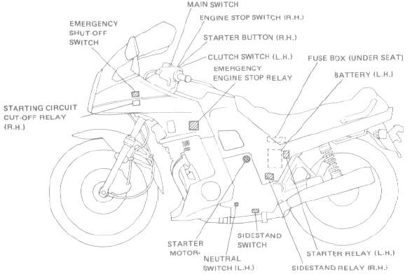
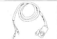
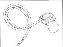
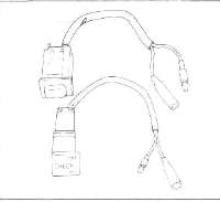
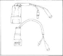
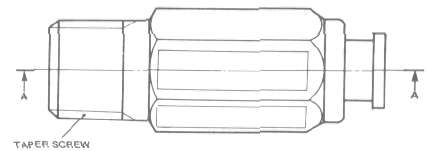
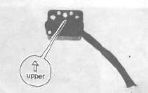
Switches and RelaysEMERGENCY SHUT-OFF SWITCH
The emergency shutoff switch is a mechanical switch and mounted behind the headlight. This switch will shut off the ignition system if for any reason the motorcycle reaches a lean angle of 60 degrees or more from vertical.
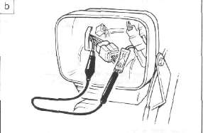
Removal
1. Remove the required fairing.
2. Disconnect the lead wires from the wire harness and pull out the switch assembly from its rubber mounting harness.
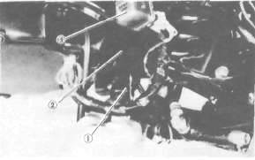
1. Emergency shut-off switch 2. Rubber mounting 3. Fuel pump relay
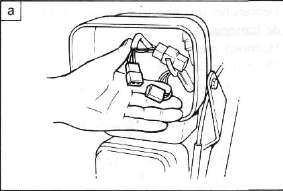
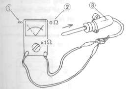
Inspection
1. Connect the pocket tester leads as shown.
2. The tester (with ohms x 100 scale) needle should show infinity {∞) when the switch is positioned vertically as shown. Replace the switch if it shows 0Ω
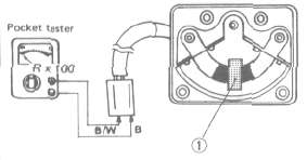
1. Weight contact
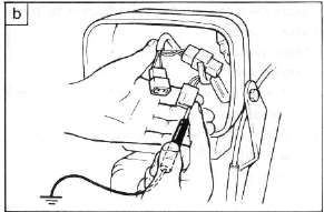
3. The tester (with ohms x 100 scale) needle should swing to 0Ω when the switch is leaned about 60 degrees or more to either left or right from the vertical position.
Replace the switch if it shows infinite resistance (∞).
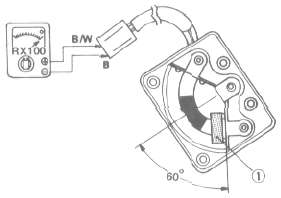
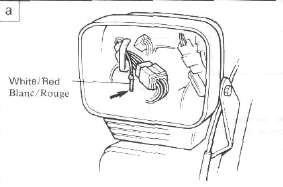
Installation
CAUTION: Install the switch with the arrow pointing up. or the switch will not operate correctly.
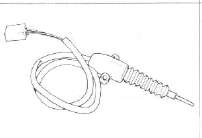
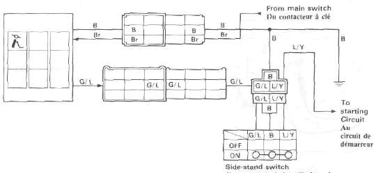
SIDESTAND SWITCH
1. Remove the seat.
2. Remove the side panels as one piece.
3. Disconnect the connector from the wiring harness.
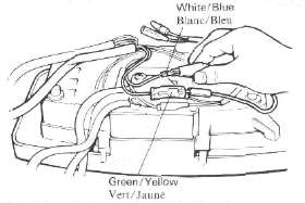
4. Connect the pocket tester leads as shown, and set the tester selector to ohm x 1. When the sidestand is up, the tester should read zero ohms. When the side-stand is down, the tester should read infinity.
|
SIDESTAND |
SWITCH |
L/Y |
B |
G/L |
|
UP |
FREE |
|
|
|
|
DOWN |
PUSH |
|
|
|


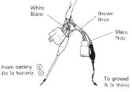
Also you can remove the switch and check it as a unit.
1. Push 2. Free 3. Sidestaod switch
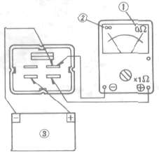
SIDESTAND RELAY
1. Remove the seat and the side panels.
2. Disconnect the connector and remove the sidestand relay.
3, Check the resistance of the relay coil windings with the pocket tester. If the resistance is not within specification, replace the relay.
4. Check the relay contact breaker points with the pocket tester and a 12 volt battery. Connect the leads as shown in the illustration. If the resistance readings do not equal those shown in the illustration, replace the relay.
SIDESTAND RELAY
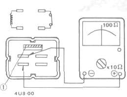
1. When the battery is connected. 2. When the battery is disconnected.
3. 12 volt battery
STARTING CIRCUIT CUT-OFF RELAY
1. Remove the required fairing.
2. Disconnect the connector.
3. Remove the starting circuit cut-off relay.
1. Starter circuit cut-off relay
4. Check the resistance of the relay coil windings with the pocket tester. If the resistance is not within specification, replace the relay.
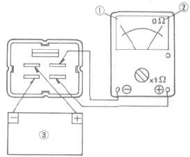
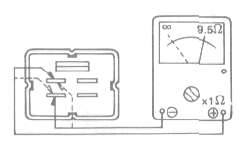
STARTING CIRCUIT CUT-OFF RELAY
5. Check the relay function with a 12 volt battery and the pocket tester. Connect the leads as shown in the illustration. If the resistance readings do not equal those shown in the illustration, replace the relay.
CAUTION: Wrong connection of the battery leads may cause damage to the relay diode.
6. Check the diode in the starting-circuit cut-off relay with the pocket tester as shown in the illustration. Replace the relay if the diode is damaged.
1. When the balterv is conrwcted. 2. When the battery is disconnected.
3. 12 volt battery
NOTE: Only the Yamaha Pocket Tester will give a 9.5Ω reading when testing continuity. The particular characteristics of other testers will vary the continuity test readings.
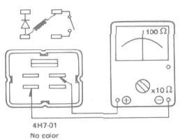
FUEL PUMP RELAY
1. Remove the required fairing.
2. Disconnect the connector.
3. Remove the fuel pump relay.
1. Fuel pump relay
4. Check the resistance of the relay coil windings with the pocket tester. If the resistance is not within specification, replace the relay.
FUEL PUMP RELAY
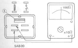
1. Red
5. Check the relay function with a 12 volt battery and the pocket tester. Connect the leads as shown in the illustration. If the resistance readings do not equal those shown in the illustration, replace the relay.
1. When the battery is connected. 2 When the battery is disconnected.
3. 12 volt battery
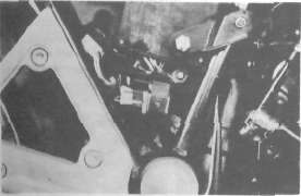
Emergency engine stop relay inspection
1. Remove the seat.
2. Remove the side panels as one piece.
3. Remove the lower panel securing bolts (2X2).

1. Side panel 2. Lower panel
4. Remove the fuel tank.
5. Disconnect the connecter and remove the emergency engine stop relay.
1. Emergency engine stop relay
6. Check the relay as shown in "Sidestand relay inspection."