Chassis Maintenance
Chassis MaintenanceFront Fork, Rear Shock
Front Fork, Rear ShockFront fork and rear shock absorber adjustment
Front fork air pressure
1. Elevate the front wheel by placing the motorcycle on the center stand.
NOTE:
When checking and adjusting the air pressure, there should be no weight on the front end of the motorcycle.
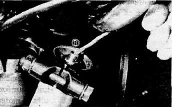
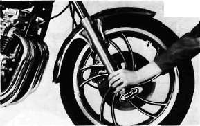
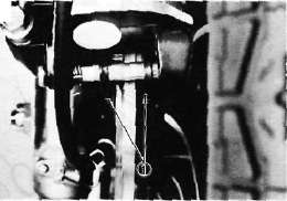
2. Remove the air valve cap from left fork.
3. Using the air gauge, check and adjust the air pressure.
If the air pressure is increased, the suspension becomes stiffer and if decreased, it becomes softer.
To increase: Use a manual air pump or other pressurized air supply.
To decrease: Replace the air by pushing the valve pin.

1. Air gauge
Standard air pressure: 39.2 kPa (0.4 kg/cm2, 5.7 psi)
Maximum air pressure:118 kPa (1.2 kg/cm2, 17 psi)
Minimum air pressure: 39.2 kPa (0.4 kg/cm2, 5.7 psi)
* Never exceed the maximum pressure, or oil seal damage may occur.
4. Install the air valve caps securely.
Rear shock absorber adjustment
1. Spring preload
If the spring seat is raised, the spring becomes stiffer and if lowered, it becomes softer.
Standard position — A A. position — Softest E. position — Stiffest

2. Damping force
Turn the damping force adjuster by your fingers to increase or decrease the damping force. If it is difficult to turn it with your fingers, use a screw driver.
Standard position — No. 1
No. 1 — Minimum damping force No. 4 — Maximum damping force

1. Damping force adjuster
NOTE:
When adjusting the damping force, the adjuster should be placed in the clicked position. If not, the damping force will be set to the maximum (No. 4).
Always adjust both the right and left absorbers to the same position.
Recommended combination of the front fork and the rear shock absorber. Use this table as guidance to meet specific riding conditions and motorcycle load.
|
\ |
Front fork |
Rear shock absorber |
Loading condition |
||||
|
Air pressure |
Spring seat |
Damping adjuster |
Solo rider |
With passenger |
With accessory equipments |
With accessory equipments and passenger |
|
|
1. |
0.4 ~ 0.8 kg/cm2 (5.7 ~ 11.4 psi) |
A~C |
1 |
O |
|||
|
2. |
0.4 ~ 0.8 kg/cm2 (5.7-11.4 psi) |
A~C |
2 |
O |
O |
||
|
3. |
0.4 — 0.8 kg/cm2 (5.7 ~ 11.4 psi) |
C~E |
3 |
O |
O |
||
|
4. |
0.8-1.2 kg/cm2 (11.4-17.1 psi) |
E |
4 |
O |
O |
||
Front Fork Oil Change
Front Fork Oil ChangeFront fork oil change
Warning:
1. Fork oil leakage can cause loss of stability and safe handling. Have any problem corrected before operating the motorcycle.
2. Securely support the motorcycle so there is no danger of it falling over.
1. Raise the motorcycle so that there is no weight on the front end of the motorcycle.
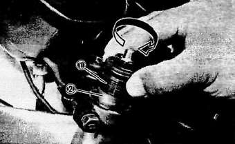
2. Remove the rubber air valve cap from the the top of each fork.
3. Keep the valve open by pressing it for several seconds so that the air can be let out of the inner tube.
1. Push
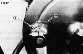
4. Loosen the pinch bolts and remove the cap bolt from each inner tube.
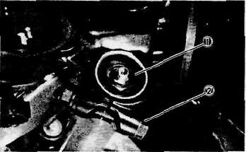
1. Cap bolt
2. Pinch bolt
5. Place an open container under each drain hole. Remove the drain screw from each outer tube.
Warning:
Do not allow oil to contact the disc brake components. If any oil should contact the brake components it must be removed before the motorcycle is operated. Oil will cause diminished braking capacity and will damage the rubber components of the brake assembly.
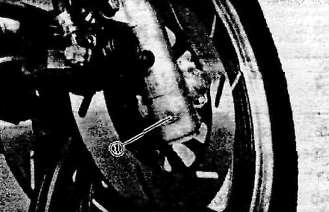
1. Drain screw
6. When most of the oil has drained, slowly raise and lower the outer tubes to pump out the remaining oil.
7. Inspect the drain screw gasket. Replace if damaged. Reinstall the drain screw.
8. Pour the specified amount of oil into the fork inner tube.
Front fork oil (each fork): 278 cm3(9.8 Imp oz)
Recommended oil:
Yamaha Fork Oil 20 wt or SAE 10W30 type SE motor oil
9. After filling, slowly pump the forks up and.down to distribute the oil.
10. Inspect the O-ring on the cap bolt. Replace if damaged.
11. Reinstall the cap bolt and the rubber cap. Then, tighten the pinch bolts.
1. Cap bolt
2. Spacer
Tightening torque:
Cap bolt:23 Nm (2.3m.kg, 17ft-lb)
Pinch bolt:20 Nm (2.0m-kg, 14 ft-lb)
12. Fill the fork with air using a manual air pump or other pressurized air supply. Refer to "Front fork and rear shock absorber adjustment" for proper air pressure adjusting.
Maximum air pressure:
118kPa (1.2kg/cm2,17psi) Do not exceed this amount.
Steering head, Cables and Pivot points
Steering head, Cables and Pivot pointsF. Steering Head Adjustment
The steering assembly should be checked periodically for looseness.
1. Raise the front end of the motorcycle so that there is no weight on the front wheel.
2. Grasp the bottom of the forks and gently rock the fork assembly backward and forward, checking for looseness in the steering assembly bearings.
3. If there is looseness in the steering head, loosen the steering stem and front fork pinch bolts and steering fitting bolt.
4. Use a steering nut wrench to loosen top steering fitting nut. The top nut serves as a lock nut.
5. Tighten the lower steering fitting nut until the steering head is tight, but does not bind when forks are turned.
6. Retighten the top steering fitting nut, steering fitting bolt and steering stem and front fork pinch bolts, in that order.
7. Recheck steering adjustment to make sure there is no binding when the forks are moved from lock to lock. If necessary, repeat adjustment procedure.
G. Cable Inspection and Lubrication
WARNING:
Damage to the outer housing of the various cables, may cause corrosion and often free movement will be obstructed. An unsafe condition may result so replace such cables as soon as possible.
1. If the inner cables do not operate smoothly, lubricate or replace them.
Recommended lubricant:
Yamaha Chain and Cable Lube or SAE 10W/30 motor oil
H. Throttle Cable and Grip Lubrication
The throttle twist grip assembly should be greased when the cable is lubricated, since the grip must be removed to get at the end of the throttle cable. Two screws clamp the throttle housing to the handlebar. Once these two are removed, the end of the cable can be held high to pour in several drops of lubricant. With the throttle grip disassembled, coat the metal surface of the grip assembly with a suitable all-purpose grease to cut down friction.
I. Rear Arm Pivot Bearings
The swing arm must pivot freely on its bearings but not have any excess play. Check and adjust pivot bearings if necessary. (Refer to CHAPTER 5. SWING ARM).
J. Brake and Change Pedals/Brake and Clutch Levers
Lubricate the pivoting parts of each lever and pedal.
Recommended lubricant: Yamaha Chain and Cable Lube or SAE 10W/30 motor oil
K.Center and Side Stand Pivots
Lubricate the center and side stands at their pivot points.
Recommended lubricants: Yamaha Chain and Cable Lube or SAE 10W/30 motor oil
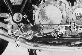
Adjustable Footrest
Adjustable FootrestADJUSTABLE FOOTREST

Recommended lubricants: Yamaha chain and cable lube or SAE10W30 motor oil
1. Footrest(Left)
2. Shift pedal
3. Shift adjuster
4. Shift arm
5. Lock nut (Left thread)
6. Lock nut
7. Footrest (Right)
8. Brake pedal
9. Brake pedal bush
10. Brake pedal boss
11. Brake shaft
12. Brake rod adjuster
13. Brake adjuster
14. Lock nut (Left thread)
15. Lock nut
Footrest adjustment
Right 1. Loosen the lock nuts and self-locking nut.

1. Lock nut 2. Self-locking nut
2. Move the footrest either way to suit the rider's preference. (Six possible positions only) Then secure the self-locking nut.
Tightening torque: 55Nm(5.5m-kg,40ft-lb)
3. By turning the adjuster clockwise or counterclockwise, adjust the brake pedal position so taht its top end is approx. 20 mm (0.8 in) below the top of the footrest.
4. Secure the lock nuts.
1. Adjuster 4. Pedal height 20 mm (0.8 in) (For pedal height)
2. Lock nut 5. Free play 20 ~ 30 mm (0.8 ~ 1.2 in)
3. Footrest
WARNING:
After adjusting the pedal height, the brake pedal free play should be adjusted.
Left
1. Loosen the lock nuts and bolt.
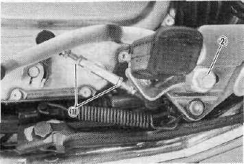
1. Lockout 2. Bolt
2. Move the footrest either way to suit the rider's preference. Then secure the bolt.
Tightening torque: 55 Nm (5.5 m-kg, 40 ft-lb)
3. By turning the adjuster clockwise or counterclockwise, adjust the position of the change pedal so that its peg center is approx. 20 mm (0.8 in) below the top of the footrest.
4. Secure the lock nuts.
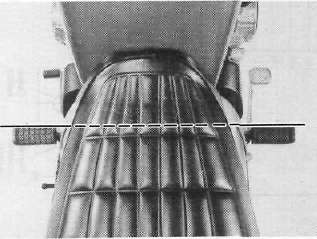
NOTE:
Viewed from the top, both adjusted footrests must be in line with each other.
1. Adjuster 3. Footrest
(For pedal height) 4. Pedal height 20 mm (0.8 in)
2. Lock nut
Overhauling
1. When installing the brake pedal onto the brake shaft, be sure to align their marks. The brake adjuster should be positioned as shown below.

1. Standard brake adjuster length = 131 mm (5.16 in)
2. Brake shaft
3. Brake pedal boss
2. When installing the shift arm onto the shift shaft, align the split portion of the shift arm end with the mark on the crankcase cover. The shift adjuster length should be set as shown below.

1. Standard shift adjuster length = 94 mm (3.70 in)
2. Split in the end of shift arm
3. Crankcase cover mark Angle A = Angle B = 90°
Petcock, Brakes and Tires
Petcock, Brakes and TiresA. Fuel Petcock
If the fuel petcock is leaking or excessively contaminated, it should be removed from the fuel tank and inspected.
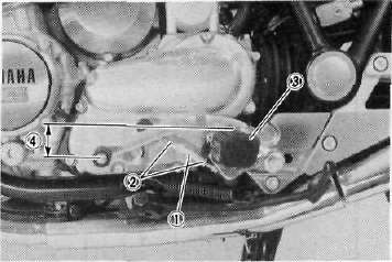
1. Remove the fuel tank and position it so that fuel will not spill when the petcock is removed.
2. Remove the petcock and inspect the filter screen. Replace the filter if seriously contaminated.
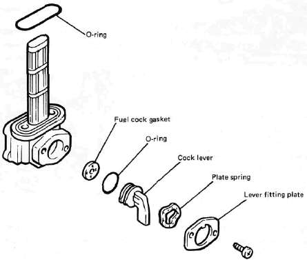
3. Remove the screws on the front and rear of the petcock and remove the plate, gaskets, lever, and diaphragm.
4. Inspect all components and replace any that are damaged. If the diaphragm is in any way damaged, or the petcock body gasket surfaces scratched or corroded, the petcock assembly must be replaced. If there is abrasive damage to any component, the fuel tank must be drained and flushed.
5. Reassemble the petcock and install it on the fuel tank.
B. Front and Rear Brake
1. Brake adjustment
a. Front brake lever free play adjustment. The brake can be adjusted by simply adjusting the free play of the brake lever. The piston in the caliper moves forward as the brake pad wears out, automatically adjusting the clearance between the brake pads and brake disc.
CAUTION:
Proper lever free play is essential to avoid excessive brake drag.
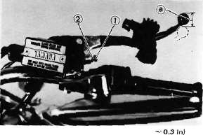
1. Adjuster 2. Lock nut a. 5~8 mm (0.2 - 0.3 in)
1) Loosen the adjuster lock nut on the brake lever.
2) Turn the adjuster so that the brake lever movement at the lever end is 5- 8 mm (0.2 ~ 0.3 in) before the adjuster contacts the master cylinder piston.
3) After adjusting, tighten the lock nut.
CAUTION:
Proper lever free play is essential to avoid excessive brake drag.
b. Rear brake pedal height adjustment
1) Loosen the adjuster lock nut (for pedal height).
2) By turning the adjuster bolt clockwise or counterclockwise, adjust the brake pedal position so that its top end is approximately 20 mm (0.78 in) below the footrest top end.
3) Secure the adjuster lock nut.
WARNING:
After adjusting the pedal height, the brake pedal free play should be adjusted.
c. Rear brake pedal free play adjustment
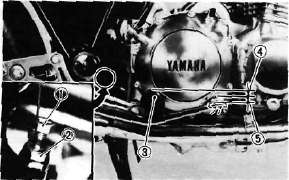
|
1. Adjuster bolt |
3. Footrest |
|
(for pedal height) |
4. Pedal height 20 mm [0.8 in) |
|
2. Lock nut |
5. Free play 20~ 30 mm (0.8-^ 1.2 in) |
Turn the adjuster on the brake rod clockwise or counterclockwise to provide the brake pedal end with a free play of 20 — 30 mm (0.8-1.2 in).
NOTE:-
Check to see whether or not the brake light operates correctly after adjusting.
2. Front brake pad and rear brake shoe
check a. Front brake pad
To check, look at the pad in front. If any pad is worn to the wear limit, replace the both pads in the caliper.
Front
1. Wear indicator
b. Rear brake shoe
To check, see the wear indicator position while depressing the brake pedal. If the indicator reaches to the wear limit line, replace the shoes.
1. Wear limit 2. Wear indicator
3. Brake fluid
Insufficient brake fluid may allow air to enter the brake system, possibly causing the brake to become ineffective. Check the brake fluid level and replenish when necessary observing these precautions:
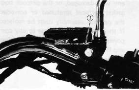
1. Lower level
a. Use only the designated quality brake fluid; otherwise, the rubber seals may deteriorate, causing leakage and poor brake performance.
Recommended brake fluid: DOT #3
b. Refill with the same type and brand of brake fluid; mixing fluids may result in a harmful chemical reaction and lead to poor performance.
c. Be careful that water or other contamination does not enter the master cylinder when refilling. Water will significantly lower the boiling point and may result in vapor lock.
d. Brake fluid may erode painted surfaces or plastic parts. Always clean up spilled fluid immediately.
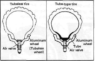
C. Tubeless Tires and Aluminum Wheels
This motorcycle is equipped with aluminum wheels designed to be compatible with either tube or tubeless tires. Tubeless tires are installed as standard equipment.
WARNING:
Do not attempt to use tubeless tires on a wheel designed for use only with tube-type tires. Tire failure and personal injury may results from sudden deflation.
Tube-type Wheel — Tube-type tires only
Tubeless-type Wheel — Tube-type or Tubeless tires
When using tube-type tires, be sure to install the proper tube also.
To insure maximum performance, long service, and safe operation, note the following precautions:
1. Check tire pressure, before riding, adjust as necessary.
2. Before operation, always check the tire surfaces for wear and/or damage; look for cracks, glass, nails, metal fragments, stones, etc. Correct any such hazard before riding.
3. Always inspect the aluminum wheels before a ride. Place the motorcycle on the center stand and check for cracks, bends or warpage of the wheels. Do not attempt even small repairs to the wheel. If a wheel is deformed or cracked, it must be replaced.
4. Tires and wheels should be balanced whenever either one is changed or replaced. Failure to have a wheel assembly balanced can result in poor performance, adverse handling characteristics, and shortened tire life.
5. After installing a tire, ride conservatively to allow the tire to seat itself on the rim properly. Failure to allow proper seating may cause tire failure resulting in damage to the motorcycle and injury to the rider.
6. After repairing or replacing a tire, check to be sure the valve stem lock nut is securely fastened. If not, torque it as specified.
Tightening torque: 0.15 m-kg (1.1 ft-lb)