Middle Gear Service
Middle Gear ServiceMIDDLE GEAR SERVICE
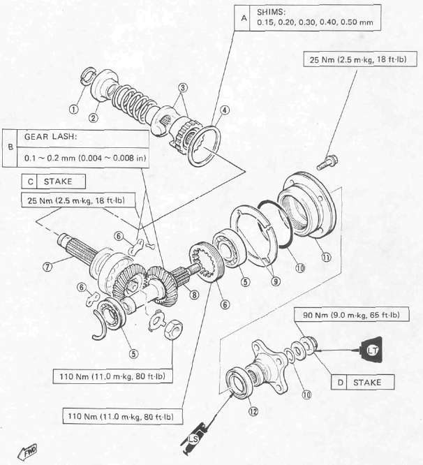
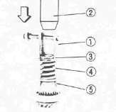
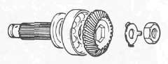
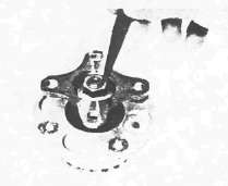
1 Spring retainers
2 Spring seat
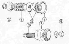
3 Damper cams
4 Midde drive gear shim
5 Bearing
6 Bearing retainer
7 Middle drive shaft
8 Middle driven shaft
9 Shim
10 O-ring
11 Bearing housing
12 Oil seal (35 x 5 0x6)
Gear Lash Measurement and Adjustment
Gear Lash Measurement and AdjustmentGEAR LASH MEASUREMENT
NOTE:
The middle gear lash can be checked only when the gears are installed in the crankcase.
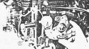
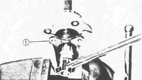
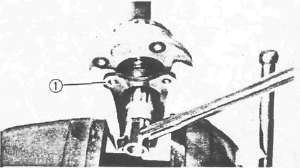
1. Attach:
• Middle Drive Pinion Holder (90890-04051) 1 .
NOTE:
Before installing the tool, loosen the holder bolt all the way out and after installation tighten this bolt as tight as necessary (finger tight is generally sufficient).
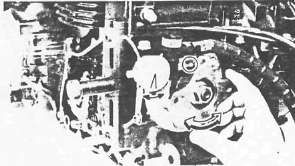
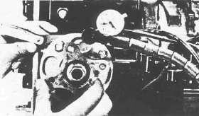
2. Attach a dial gauge against the middle drive flange as shown
3. Measure middle gear lash by rotating the flange gently back and forth. Follow Gear Lash Adjustment procedure if lash is not within specified limits.
Middle Gear Lash: 0.1 - 0.2 mm (0.004 - 0.008 in)
NOTE: Check this engagement at 4 points. If the gear lash exceeds the specified limit and adjustment is necessary, the engine or swing arm should be removed from the motorcycle.
GEAR LASH ADJUSTMENT
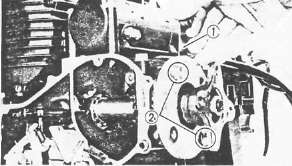
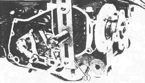
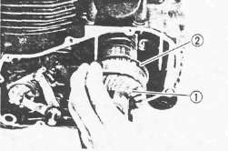
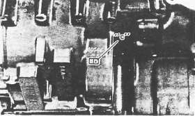
1. Install the driven gear housing assembly into the crankcase leaving about a 2 mm (0.080 in) gap 1 between the housing and crankcase and install the two bolts 2 to the bearing housing 180° opposite to each other.
2. Attach:
• Middle Drive Pinion Holder (90890-04051)1 .
• Dial gauge
3. Slowly tighten the bolts alternately until the dial gauge lash measurement reaches 0.2 mm (0.008 in).
4. Measure the clearance between the bearing housing and the crankcase. This clearance is the shim size required.
5. Install the proper sized shim(s) 1
6. Tighten the bearing housing.
Bearing Housing: 25 Nm (2.5 mkg, 18 ft-lb)
7. Recheck the middle gear lash. Readjust if necessary.
Middle Gear Removal and Disassembly
Middle Gear Removal and DisassemblyREMOVAL
Middle Drive Gear
NOTE:
Middle drive gear and its shims can be removed without separating the engine.
1. Remove the clutch cover. Refer to "ENGINE DISASSEMBLY."

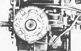
2. Strike the middle drive shaft out 1
3. Remove
• Middle drive shaft 1
•Shims 2
DISASSEMBLY Middle Drive Gear
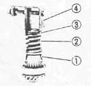
1. Remove:
• Spring retainer. Use Damper Compressor (90890-04090) 1 with hydraulic press 2 .
• Spring seat 3
• Spring 4
• Damper cam 5
6 Middle drive shaft nut
7 Bearing
8 Shim
9 Middle drive shaft
NOTE:
Perform following steps only if middle-drive-shaft bearing or gear must be replaced.
2. Secure middle drive shaft in a vise.
3. Flatten the locking collar of the nut with a center punch.
4. Remove:
• Middle drive shaft nut
• Bearing
• Middle drive pinion
Middle Driven Gear
1. Support the drive flange in a vise securely.
2. Remove:
• Flange holding nut
• Flange 1
Middle Gear Inspection and Reassembly
Middle Gear Inspection and ReassemblyINSPECTION
1. Check
• teeth of middle gear for discoloration/Pitting/Wear. If necessary, replace all middle gears as a set.
• Damper cam surfaces for wear/Unsmooth action. Replace if necessary.
2. Check bearing movement. Rotate the race by finger and replace if rough.
ASSEMBLY AND ADJUSTMENT
1. Select proper middle-drive-gear shim.
NOTE:
Select proper middle-drive-gear shim whenever crankcase and/or middle gears are replaced.
Shim thickness calculation:
Calculate shim thickness using formula below:
Shim thickness (A) = c - a - b
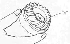
a = 43 plus or minus the number printed on end of middle drive shaft.
b = a bearing thickness. (Considered constant)
c = 60 plus the number found on the upper crankcase half near the main bearing selection numbers:
For example:
If middle drive shaft is marked "+03" and crankcase is tamped "45".
a= 43 + 0.03 = 43.03 mm
c= 63 + 0.45 = 60.45 mm
b= 16.94 mm (Constant)
A = 60.45 - 43.03 - 16 .94 = 0.48 Calculated shim thickness is 0.48 mm.
Available shim thickness: 0.15 mm, 0.30 mm, 0.40 mm, 0.50 mm
Because shim can only be selected in 0.05 mm increments, use following chart to round off the hundredths digit of calculated thickness, and select appropriate shim.
|
Hundredths digit |
Rounded value |
|
0,1,2 |
0 |
|
3,4,5,6 |
5 |
|
7,8,9 |
10 |
In above example, calculated shim thickness is 0.48 mm. The chart instructs you, however, to round off the 8 to 10. Thus you should use two 0.50 mm shims.
2. Install:
• Middle drive shaft bearing.
• Middle drive pinion
• Lock washer (New)
• Nut
3. Tighten the nut
4. Bend lock washer of nut into middle drive shaft slot using a center punch.
5. Assemble:
• Damper cam 1
• Spring 2
• Spring seat 3
• Spring retainer
Use a Press and Damper Compressor (90890-04090)4.
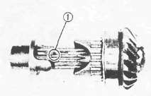
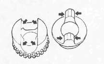
NOTE:
Install the driven damper cam onto the drive pinion shaft with the cam lobes positioned 90° from the row of shaft oil holes 1. Positioning tolerance is ±1 spline (15°) from the 90° position.
Middle Drive Shaft Nut: 110 Nm (11 m-kg, 8 0 ft-lb)
6. Install:
• Bearing housing (onto the drive pinion shaft)
• Flange
• O-ring (New) (onto the drive pinion shaft)
7. Tighten:
• Flange holding nut
Flange Holding Nut: 90 Nm (9.0 m-kg, 65 ft-lb) LOCTITE®
8. Lock the thread on the holding nut with a center punch.