D. Valve Spring and Lifters
1. Checking the valve springs
a.
This engine uses two springs of different sizes to prevent valve float
or surging. The valve spring specifications show the basic value
characteristics.
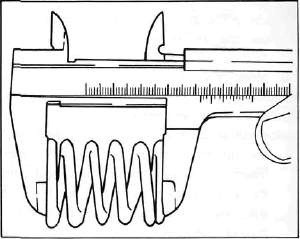
b. Even though
the spring is constructed of durable spring steel, it gradually loses
some of it's tension. This is evidenced by a gradual shortening of free
length. Use a vernier caliper to measure spring free length. If the
free length of any spring has decreased more than 2 mm (0.080 in) from
its specification replace it.
c.
Another symptom of a fatigued spring is insufficient spring pressure
when compressed. This can be checked using a valve spring compression
rate gauge. Test each spring individually. Place it in the gauge and
compress the spring first to the specified compressed length with the
valve closed (all spring specifications can be found in the previous
section, Valve Spring), then to the length with the valve open. Note
the poundage indicated on the scale at each setting. Use this procedure
with the outer springs, then the inner springs.
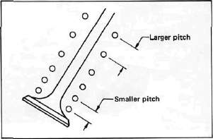
NOTE:
All valve springs must be installed with larger pitch upward as shown.
|
Valve Spring Specifications |
||
|
|
OUTER |
INNER |
|
Free length |
39.5 mm (1.55 in) |
35.9 mm (1.413 in) |
|
Installed length (valve closed) |
34.0 mm (1.339 in) |
31.0 mm (1.220 in) |
|
Installed pressure |
19.1 kg (42.1 lb) |
9.0 kg (19.8 1b) |
|
Allowable tilt from vertical |
1.6° |
|
2. Valve lifter
a.
Check each valve lifter for scratches or other damage. If the lifter is
damaged in any way, the cylinder head surface in which it rides is
probably also damaged. If the damage is severe, it may be necessary to
replace both the lifter and the cylinder head.
NOTE:
For proper valve lifter-to-head clearance, always install lifters on their original valves.
E. Camshafts, Cam chain and Cam Sprockets
1. Camshaft
a.
The cam lobe metal surface may have a blue discoloration due to
excessive friction. The metal surface could also start to flake off or
become pitted.
b. If any of the above wear conditions are readily visible, the camshaft should be replaced.
c.
Even though the cam lobe surface appears to be in satisfactory
condition, the lobes should be measured with a micrometer. Cam lobe
wear can occur without scarring the surface. If this wear exceeds a
pre-determined amount, valve timing and lift are affected. Replace the
camshaft if wear exceeds the limits.
d.
Install the camshaft on the cylinder head. Place a strip of Plastigage
between camshaft and camshaft cap as illustrated (lengthwise along
camshaft). Tighten the nuts with specified torque. Remove the camshaft
cap and determine the clearance by measuring the width of the flattened
Plastigage.
Cap nut tightening torque: 1.0m-kg(7.2ft-lb)
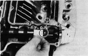
1. Plastigage
NOTE
Do not turn camshaft when measuring clearance with Plastigage.
Camshaft-to-cap clearance:
|
Standard: |
0.020-0.054 mm |
|
|
(0.0008- 0.0021 in) |
|
Maximum: |
0.160 mm (0.006 in) |
If the camshaft-to-cap clearance exceeds specification, measure camshaft bearing surface diameter.
Bearing surface diameter:
|
Standard: |
24.967-24.980 mm |
|
|
(0.9830-0.9835 in) |
1) If camshaft diameter is less than specification, causing excessive clearance, replace camshaft.
2) If camshaft is within specification and camshaft-to-cap clearance is excessive, replace cylinder head.
2. Cam chain
Except
in cases of oil starvation, the cam chain wears very little. If the cam
chain has stretched excessively and it is difficult to keep the proper
cam chain tension, the chain should be replaced.
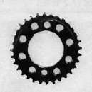
3. Cam sprockets
Check cam sprockets for obvious wear.
4, Cam chain dampers and tensioner
Inspect
the top cam chain damper (stopper guide) and two (2) vertical
(slipper-type) dampers for excessive wear. Any that shows excessive
wear should be replaced. Worn dampers may indicate an improperly
adjusted or worn-out cam chain.
- Printer-friendly version
- Log in to post comments