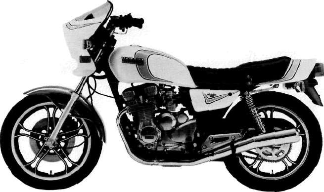
MOTORCYCLE IDENTIFICATION
A. Frame serial number
The frame serial number is stamped into the right side of the steering head pipe.
B. Engine serial number
The engine serial number is stamped into the elevated part of the right section of the engine.
NOTE:
The first three digits of these numbers are for model identifications; the remaining digits are the unit production number.
C. Vehicle identification number
The vehicle identification number is stamped on the label attached on the right side of the steering head pipe.
NOTE:
The vehicle identification number is used to identify your motorcycle and may be used to register your motorcycle with the licensing authority in your state.
Starting serial number:
XJ550RH.............4U8-000101
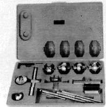
SPECIAL TOOLS
The proper special tools are necessary for complete and accurate tune-up and assembly. Using the correct special tool will help to prevent damage from improper tools or in-provised techniques.
A. For tune-up
1. Compression gauge
2. Timing light
3. Tachometer
4. Tappet adjusting tool P/N. 90890-01245-00
This tool is necessary to replace valve adjusting pads. This can also be used for the XS750, XS850. XS1100 and XJ65Q.
5. Vacuum gauge
P/N. TLU-11080-30-02
This gauge is needed for carburetor synchronization.
B. For engine service
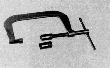
1. Clutch hub holder
P/N. TLM-90910-42-00
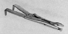
This tool is used to hold the clutch when removing or install ing the clutch boss lock nut.
2. Valve guide reamer
P/N. P/N. 90890-04066-00
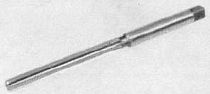
This tool must be used when replacing the valve guide.
3. Valve seat cutter
P/N. TLM-90910-43-20
This tool is needed to re-surface the valve seat.
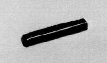
4. Valve guide remover P/N. 90890-04064-00
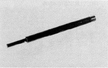
This tool must be used to remove the valve guides.
5. Valve guide installer
P/N. 90890-04065-00
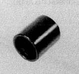
This tool is needed for proper installation of the valve guides.
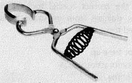
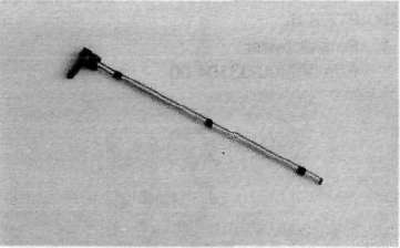
6. Valve spring compressor
P/N. 90890-01253-00
This tool must be used for removing and installing the valve
assemblies,
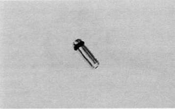
7. Piston ring compressor P/N. 90890-04047-00
This tool is used to compress piston rings when installing the cylinder.
8. Piston base
P/N. 90890-01067-00
Use 4 of these to hold the pistons during cylinder installation.
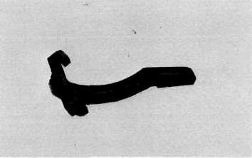
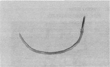
9. Rotor puller
P/N. 90890-01080-00
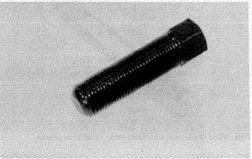
This tool is needed to remove the A,C. Generator rotor.
10. Rotor puller attachment P/N. 90890-04052-00
This tool is needed when removing the A.C. Generator rotor together with the rotor puller.
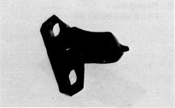
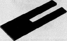
11. Rotor holding tool P/N. 90890-04067-00
This tool is used to hold the A.C. Generator rotor during removal and installation.
12. Dial gauge stand
P/N. 90890-01258-00
13. Dial gauge
P/N. 90890-03097-00
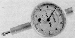
This dial gauge is used to determine piston position for correct timing.
14. YlCSshutoff tool
P/N. TLM-11080-25-00
This tool is needed for carburetor synchronization,
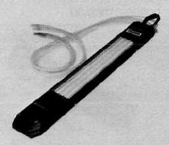
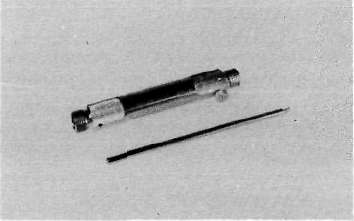
15. Fuel level gauge
P/N. 90890-01312-00
This tool is needed to measure the carburetor fuel level.
This tool is needed to hold the dial gauge.
16. Fuel level gauge adapter P/N. 90890-01329-00
This tool is needed when measuring the carburetor fuel level together with fuel level gauge.
C. For electrical components The uses of thee tools are described in CHAPTER 6. 1. Pocket tester
P/N. 90890-03104-00
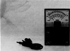
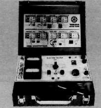
2. Electro tester
P/N. 90890-03021-00
- Printer-friendly version
- Log in to post comments