VALVE CLEARANCE ADJUSTMENT

(1)Pad (2) Valve lifter (3) Valve retainer (4)Spring seat (5)inner spring (6) Outer spring (7) Spring seat (8) Oil seal (9) Valve
|
A |
VALVE CLEARANCE (COLD): |
|
|
B |
Intake: |
0.11 -0.15 mm (0.0043-0.0059 in) |
|
C |
Exhaust: |
0.16-0.20 mm (0.0063-0.0079 in) |
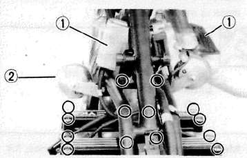
Removal
1. Remove:
• Seat
• Fuel tank
• Ignition coil covers (1)
• Horns with stay (2)
2. Disconnect:
• Spark plug caps
3. Remove:
• Spark plugs
• Cylinder head cover
4. Remove:
• Emblem plate (Left)

Inspection and Adjustment
1. Measure:
• Valve clearance
NOTE:
Be sure piston is at Top Dead Center (TDC) on compression stroke when measuring clearance.
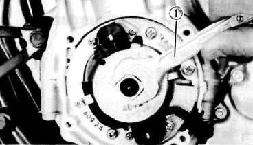
Valve clearance measurement steps:
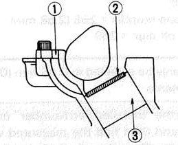
• Turn the crankshaft counterclockwise with a 19 mm spanner (1) .
NOTE:
Valve clearance must be measured when the engine is cool to the touch.
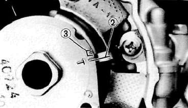
• Align the "T" mark (for the No. 1 or No. 4 cylinder) on the timing plate with the stationary pointer (2). When the "T" mark is aligned with the stationary pointer (2), the piston is at top dead center TDC.
(3) Firing range for No. 1 cylinder
• Measure the valve clearance using a Feeler Gauge.
• Record the measured amount if the clearance is incorrect.
Intake Valve (cold): 0.11 —0.15 mm (0.0043 ~ 0.0059 in)
Exhaust Valve (cold): 0.16 —0.20 mm (0.0063 ~ 0.0079 in)
• Measure valve clearance, in sequence, for Nos. 2, 4, and No. 3 cylinders. Out of specification — Adjust clearance.
Firing Sequence: 1-2-4-3
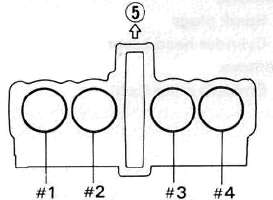
(5) Front
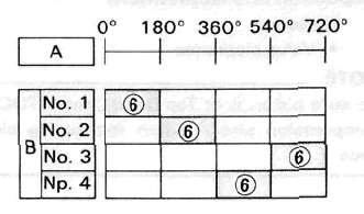
A Crankshaft counterclockwise turning angle.
B Cylinder
(6) Combustion
2. Adjust:
• Valve clearance
Valve clearance adjustment steps:
• Position the valve lifter slots (intake and exhaust) opposite each other.
• Turn the camshaft until the lobe fully depresses the valve lifter and opens the valve.
• Attach the Tappet Adjusting Tool (1) (YM-01245) onto the cylinder head.
NOTE:
Make sure that the tool contacts the lifter (3) only, and not the pad (2).
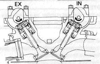
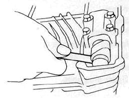
• Carefully rotate the camshaft so that the pads can be removed. To avoid cam touching the adjusting tool, turn cams as shown.
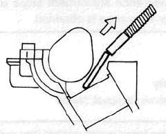
Intake: Carefully rotate CLOCKWISE. Exhaust: Carefully rotate COUNTERCLOCKWISE.
• Remove the pads (2) from the lifters. Use a small screwdriver and a magnetic rod for removal.Note pad numbers.
• Select the proper valve adjusting pad from the chart below:
|
Pad range |
Pad Availability: 25 increments |
|
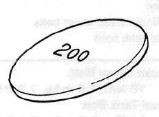
No. 200 - 2.00mm (0.079 in) |
Pad stepped in 0.05 mm (0.002 in) increments |
NOTE:
Thickness of each pad is marked on the pad face that contacts the valve lifter (not the cam).
• Round off the hundredths digit of the original pad number to the nearest 0.05 mm increment.
|
Hundredths digit |
Rounded valve |
|
0 or 2 |
0 |
|
5 |
NOT ROUNDED OFF |
|
8 |
10 |
EXAMPLE:
Original pad number = 258 (2.58 mm)
Rounded off digit = 260
NOTE:
Pad can only be selected in 0.05 mm (0.002 in) increments.
Determine the required replacement pad thickness by one of the two following methods:
Shim calculation method:
Since all shims come in .05mm (.002") increments, you can quickly calculate the required size without a chart.
If the measured clearance is within 0.05mm (0.002") of the required clearance, then no change is needed.
If the measured clearance greater than 0.05mm (0.002") but 0.10mm (0.004") or less different than the required clearance then the next size shim is required.
If the measured clearance greater than 0.10mm (0.004") but 0.15mm (0.006") or less different than the required clearance then the next size shim is required.
Clearances that are too small require thinner shims. Clearances that are too large require thicker shims.
Example: Required exhaust valve clearance is 0.16~0.20mm. Measured clearance is 0.12mm (gap too small). Installed shim is Y270. Required shim is one size thinner: Y265.
Shim Chart Lookup Method:
• Locate the "Installed Pad Number" on the chart, and then find the measured valve clearance. The point where these coordinates intersect is the new pad number.
NOTE:
Use the new pad number as a guide only as the number must be verified.
Pad number verification steps:
• Install the new pad with the number down.
• Remove the adjusting tool.
• Recheck the valve clearance.
• If the clearance is incorrect, repeat all of the clearance adjustment steps until the proper clearance is obtained.
Assembly
1. Reverse removal steps.
NOTE:
Inspect the head cover gasket and replace it if damaged.
2. Tighten:
• Cylinder head cover bolts
• Fuel tank bolts
Head Cover Bolt:
10Nm(1.0mkg, 7.2 ftlb)
Fuel Tank Bolt:
10Nm(1.0rrvkg, 7.2 ftlb)
INTAKE
|
MEASURED |
INSTALLED PAD NUMBER |
||||||||||||||||||||||||
|
200 |
205 |
210 |
215 |
220 |
225 |
230 |
235 |
240 |
245 |
250 |
255 |
260 |
265 |
270 |
275 |
280 |
285 |
290 |
295 |
300 |
305 |
310 |
315 |
320 |
|
|
0.00 - 0 05 |
200 |
205 |
210 |
215 |
220 |
225 |
230 |
235 |
240 |
245 |
250 |
255 |
260 |
265 |
270 |
275 |
280 |
285 |
290 |
295 |
300 |
305 |
310 |
||
|
0.06 - 0 10 |
200 |
205 |
210 |
215 |
220 |
225 |
230 |
235 |
240 |
240 |
260 |
255 |
260 |
265 |
270 |
275 |
280 |
285 |
290 |
295 |
300 |
305 |
310 |
315 |
|
|
0 11 - 0.15 |
|||||||||||||||||||||||||
|
0 16 - 0.20 |
205 |
210 |
215 |
220 |
225 |
230 |
235 |
240 |
245 |
250 |
255 |
260 |
265 |
270 |
275 |
280 |
285 |
290 |
295 |
300 |
305 |
310 |
315 |
320 |
|
|
0.21 - 0.25 |
210 |
215 |
220 |
225 |
230 |
235 |
240 |
245 |
250 |
255 |
200 |
265 |
270 |
275 |
280 |
285 |
290 |
295 |
300 |
305 |
310 |
315 |
320 |
||
|
0 26 - 0.30 |
215 |
220 |
225 |
230 |
235 |
240 |
245 |
250 |
255 |
260 |
265 |
270 |
275 |
280 |
285 |
290 |
295 |
300 |
305 |
310 |
315 |
320 |
|||
|
0.31 - 0.35 |
220 |
22ft |
230 |
23ft |
240 |
245 |
250 |
255 |
260 |
265 |
270 |
275 |
280 |
285 |
290 |
295 |
300 |
305 |
310 |
315 |
320 |
||||
|
0 36 - 0 40 |
225 |
230 |
235 |
240 |
245 |
250 |
255 |
260 |
265 |
270 |
275 |
280 |
285 |
290 |
295 |
300 |
305 |
310 |
315 |
320 |
|||||
|
0 41 - 0 45 |
230 |
235 |
240 |
245 |
250 |
255 |
260 |
265 |
270 |
275 |
280 |
285 |
290 |
295 |
300 |
305 |
310 |
315 |
320 |
||||||
|
0.46 - 0 50 |
235 |
240 |
245 |
250 |
255 |
260 |
265 |
270 |
275 |
280 |
285 |
290 |
295 |
300 |
305 |
310 |
315 |
320 |
|||||||
|
0 51 - 0.55 |
240 |
245 |
250 |
255 |
260 |
265 |
270 |
275 |
280 |
285 |
290 |
295 |
300 |
305 |
310 |
315 |
320 |
||||||||
|
0 56 - 0 60 |
245 |
250 |
255 |
260 |
265 |
270 |
275 |
280 |
285 |
290 |
295 |
300 |
305 |
310 |
315 |
320 |
|||||||||
|
0.61 - 0.65 |
250 |
255 |
260 |
265 |
270 |
275 |
280 |
285 |
290 |
295 |
300 |
305 |
310 |
315 |
320 |
||||||||||
|
0 66 - 0.70 |
255 |
260 |
265 |
270 |
275 |
280 |
285 |
290 |
295 |
300 |
305 |
310 |
315 |
320 |
|||||||||||
|
0.71 - 0.75 |
260 |
265 |
270 |
275 |
280 |
285 |
290 |
295 |
300 |
305 |
310 |
315 |
320 |
||||||||||||
|
0.76 - 0 80 |
265 |
270 |
275 |
280 |
285 |
290 |
295 |
300 |
305 |
310 |
315 |
320 |
|
||||||||||||
|
0.81 - 0.85 |
270 |
275 |
280 |
285 |
290 |
295 |
300 |
305 |
310 |
315 |
320 |
||||||||||||||
|
0 86 - 0 90 |
275 |
280 |
285 |
290 |
295 |
300 |
305 |
310 |
315 |
320 |
VALVE CLEARANCE (cold): |
||||||||||||||
|
0.91 - 0.95 |
280 |
285 |
290 |
295 |
300 |
305 |
310 |
315 |
320 |
||||||||||||||||
|
0.96 - 1 00 |
285 |
290 |
295 |
300 |
305 |
310 |
315 |
320 |
0.11 to 0.15 mm (0.004 — 0.006 in) |
||||||||||||||||
|
1.01 - 1.05 |
290 |
295 |
300 |
305 |
310 |
315 |
320 |
||||||||||||||||||
|
1.06 - 1.10 |
295 |
300 |
305 |
310 |
315 |
320 |
Measured clearance is 0.32 mm (0.013 in) |
||||||||||||||||||
|
1.11 - 1.15 |
300 |
305 |
310 |
315 |
320 |
||||||||||||||||||||
|
1.16 - 1.20 |
305 |
310 |
315 |
320 |
Pad number : (example) |
||||||||||||||||||||
|
1 21 - 1 25 |
310 |
315 |
320 |
||||||||||||||||||||||
|
1 26 - 1 30 |
315 |
320 |
Pad No. 255 = 2.55 mm (0.100 in) |
||||||||||||||||||||||
|
1.31 - 1 35 |
320 |
||||||||||||||||||||||||
EXHAUST
|
MEASURED |
INSTALLED PAD NUMBER |
||||||||||||||||||||||||
|
200 |
205 |
210 |
215 |
220 |
225 |
230 |
235 |
240 |
245 |
250 |
255 |
260 |
265 |
270 |
275 |
280 |
285 |
290 |
295 |
300 |
305 |
310 |
315 |
320 |
|
| 0.00 - 0 05 |
200 |
205 |
210 |
215 |
220 |
225 |
230 |
235 |
240 |
245 |
250 |
255 |
260 |
265 |
270 |
275 |
280 |
285 |
290 |
295 |
300 |
305 |
|||
|
0.06 - 0 10 |
200 |
205 |
210 |
216 |
220 |
225 |
230 |
235 |
240 |
245 |
250 |
255 |
260 |
265 |
270 |
275 |
280 |
285 |
290 |
295 |
300 |
305 |
310 |
||
|
0 11 - 0.15 |
200 |
205 |
210 |
215 |
220 |
225 |
230 |
235 |
240 |
245 |
250 |
255 |
260 |
265 |
270 |
275 |
280 |
285 |
290 |
295 |
300 |
305 |
310 |
315 |
|
|
0 16 - 0.20 |
|||||||||||||||||||||||||
|
0.21 - 0.25 |
205 |
210 |
215 |
220 |
225 |
230 |
235 |
240 |
246 |
250 |
255 |
260 |
265 |
270 |
275 |
280 |
285 |
290 |
295 |
300 |
305 |
310 |
315 |
320 |
|
|
0 26 - 0.30 |
210 |
215 |
220 |
225 |
230 |
235 |
240 |
245 |
250 |
255 |
260 |
265 |
270 |
275 |
280 |
285 |
290 |
295 |
300 |
305 |
310 |
315 |
320 |
||
|
0.31 - 0.35 |
216 |
220 |
225 |
230 |
235 |
240 |
24ft |
260 |
255 |
2ft0 |
20ft |
270 |
275 |
280 |
285 |
290 |
295 |
300 |
305 |
310 |
315 |
320 |
|||
|
0 36 - 0 40 |
220 |
225 |
230 |
235 |
240 |
245 |
250 |
255 |
260 |
265 |
270 |
275 |
280 |
285 |
290 |
295 |
300 |
305 |
310 |
315 |
320 |
||||
|
0 41 - 0 45 |
225 |
230 |
235 |
240 |
245 |
250 |
255 |
260 |
265 |
^70 |
2'5 |
280 |
285 |
290 |
295 |
300 |
305 |
310 |
315 |
320 |
|||||
|
0.46 - 0 50 |
230 |
235 |
240 |
245 |
250 |
255 |
260 |
265 |
270 |
275 |
280 |
285 |
290 |
295 |
300 |
305 |
310 |
315 |
320 |
|
|||||
|
0 51 - 0.55 |
235 |
240 |
245 |
250 |
255 |
260 |
265 |
270 |
275 |
280 |
285 |
290 |
295 |
300 |
305 |
310 |
315 |
320 |
|||||||
|
0 56 - 0 60 |
240 |
245 |
250 |
255 |
260 |
265 |
270 |
275 |
280 |
285 |
290 |
295 |
300 |
305 |
310 |
315 |
320 |
||||||||
|
0.61 - 0.65 |
245 |
250 |
265 |
260 |
265 |
270 |
275 |
280 |
285 |
290 |
295 |
300 |
305 |
310 |
315 |
320 |
|||||||||
|
0 66 - 0.70 |
250 |
255 |
260 |
265 |
270 |
275 |
280 |
285 |
290 |
295 |
300 |
305 |
310 |
315 |
320 |
||||||||||
|
0.71 - 0.75 |
255 |
260 |
265 |
270 |
275 |
280 |
285 |
290 |
295 |
300 |
305 |
310 |
315 |
320 |
|||||||||||
|
0.76 - 0 80 |
260 |
265 |
270 |
275 |
280 |
285 |
290 |
295 |
300 |
305 |
310 |
315 |
320 |
||||||||||||
|
0.81 - 0.85 |
265 |
2 70 |
275 |
280 |
285 |
290 |
295 |
300 |
306 |
310 |
315 |
320 |
|||||||||||||
|
0 86 - 0 90 |
270 |
275 |
280 |
285 |
290 |
295 |
300 |
305 |
310 |
316 |
320 |
VALVE CLEARANCE (cold): |
|||||||||||||
|
0.91 - 0.95 |
276 |
280 |
285 |
290 |
295 |
300 |
305 |
310 |
316 |
320 |
|||||||||||||||
|
0.96 - 1 00 |
280 |
285 |
290 |
295 |
300 |
305 |
310 |
315 |
320 |
0.16 - 0.20 mm (0.006 - 0.008 in) |
|||||||||||||||
|
1.01 - 1.05 |
285 |
290 |
295 |
300 |
305 |
310 |
315 |
320 |
|||||||||||||||||
|
1.06 - 1. 10 |
290 |
295 |
300 |
305 |
310 |
315 |
320 |
Measured clearance is 0.32 mm (0.013 in) |
|||||||||||||||||
|
1. 11 - 1. 15 |
295 |
300 |
305 |
310 |
315 |
320 |
|||||||||||||||||||
|
1. 16 - 1. 20 |
300 |
305 |
310 |
315 |
320 |
Pad number : (example) |
|||||||||||||||||||
|
1 21 - 1 25 |
305 |
310 |
315 |
320 |
|||||||||||||||||||||
|
1 26 - 1 30 |
310 |
315 |
320 |
Pad No. 255 = 2.55 mm (0.100 in) |
|||||||||||||||||||||
|
1.31 - 1 35 |
320 |
||||||||||||||||||||||||
- Printer-friendly version
- Log in to post comments