ENGINE
A. Valve clearance adjustment
NOTE:
Valve clearance must be measured with the engine and at room temperature.
1. Remove the seat, fairing components, and fuel tank. See page 35.
2. Remove the horn, flasher relay, emergency engine stop relay and spark plug lead wires.
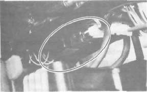
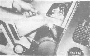
3. Remove the cylinder head cover and left crankcase cover (pick-up base cover). Care should be taken to not scratch or damage the gasket sealing surfaces.
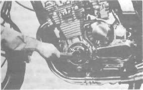
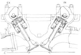
4. Turn the crankshaft with the nut on the left end of the crankshaft to turn the cams. The proper position of the cam when measuring the valve clearance is with the cam lobe directly opposite the valve lifter.
5. Insert a feeler gauge between the valve lifter and the camshaft base circle,
Intake valve clearance (cold): 0.11-0.15 mm (0.004- 0.006 in)
Exhaust valve clearance (cold): 0.16-0.20 mm (0.006- 0.008 in)
Adjustment
Valve clearance is adjusted by replacing the adjusting pad on the top of the valve lifter. Adjusting pads are available in 25 thicknesses ranging from No. 200 (2.000 mm) to No. 320 (3.20 mm) in steps of 0.05 mm. The thickness of each pad is marked on the pad face that contacts of the valve lifter (not the cam). Adjustment of the valve clearance is accomplished as follows:
1. Determine valve clearance (feeler gauge measurement.)
2. Remove adjusting pad and note number.
3. Select proper pad from appropriate chart (intake or exhaust chart).
4. Install new pad and check installed clearance.
Procedure
1. Measure valve clearance. If clearance is incorrect, record the measured amount of clearance. This must be measured carefully.
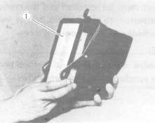
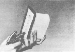
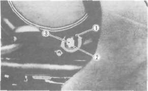
2. There is a slot in the valve lifter. This slot must be positioned opposite the blades of the tappet adjusting tool before the tools is installed.
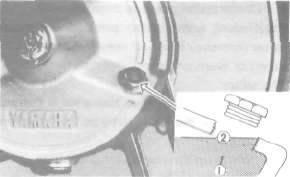
3. Turn the cam until the lobe fully depresses the valve lifter and opens the valve. Install the tappet adjusting tool as shown to hold the lifter in this depressed position.
NOTE:
The tappet adjusting tool is fastened to the cylinder head securely using one alien screw such as one used to install the cylinder head cover. Make sure that the tool contacts the lifter only, and not the pad.
CAUTION:
If the cam lobe touches the tappet adjusting tool, the stress may fracture the cylinder head. DO NOT ALLOW THE CAM TO CONTACT THE TAPPET ADJUSTING TOOL.
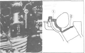
1 tappet adjusting tool 2. Adjusting pad
4. Carefully rotate the cam so that the pad can be removed. To avoid cam touching the adjusting tool, turn cams as follows: (view from left side of the motorcycle)
Intake: Carefully rotate CLOCKWISE.
Exhaust: Carefully rotate COUNTERCLOCKWISE.
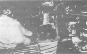
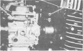
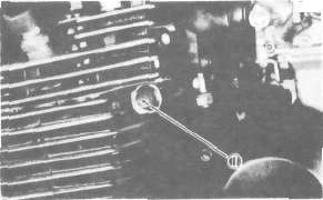
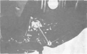
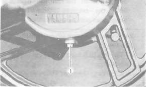
5. Remove the pad from the lifter. There is a slot in the lifter. Use a smaller screwdriver or other blade and a magnetic rod to remove the pad. Note the number on the pad.
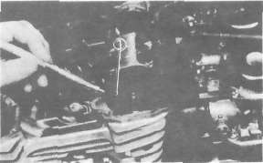
1. Adjusting pad
6 Proper pad selection is made as follows:
Chart lookup method:
(Use appropriate chart for exhaust or intake valves, attached to this page, below.)
a. Find number of original (installed) pad number on chart. Read down on chart.
b. Find measured valve clearance (from step 1) on chart. Read across.
c. At the intersection of installed pad number (down) and measured clearance (across) is a new pad number.
I EXAMPLE:
Intake valve, installed pad:
No. 250 (read down) Measured clearance:
0.32 mm (read across) New pad number: No. 270
(intersection of down & across)
NOTE: The new pad number is to be used as a guide only. Verify the correctness of this choice in the following step(s).
7. Install the new pad in the lifter. Install the pad with the number down.
8. Remove tappet adjusting tool,
9. Turn crankshaft to rotate cam several rotations. This will set the pad in the lifter.
10. Check valve clearance (step 3). If clearance is incorrect, repeat preceding steps until proper clearance is obtained.
11. Inspect head cover gasket. If bent or torn, replace gasket.
12. Reinstall removed parts in reverse order.
Alternate shim calculation method:
NOTE:
This is not a Yamaha procedure. This was developed by the XJ Owners' Group.
Since all shims come in .05mm (.002") increments, you can quickly calculate the required size without a chart.
If the measured clearance is within 0.05mm (0.002") of the required clearance, then no change is needed.
If the measured clearance greater than 0.05mm (0.002") but 0.10mm (0.004") or less different than the required clearance then the next size shim is required.
If the measured clearance greater than 0.10mm (0.004") but 0.15mm (0.006") or less different than the required clearance then the next size shim is required.
Clearances that are too small require thinner shims. Clearances that are too large require thicker shims.
Example: Required exhaust valve clearance is 0.16~0.20mm. Measured clearance is 0.12mm (gap too small). Installed shim is Y270. Required shim is one size thinner: Y265.
B. Spark plug
1. Check the electrode condition and wear, insulator color, and electrode gap,
2. Use a wire gauge for measuring the plug gap.
3. If the electrodes become too worn, replace the spark plug.
4. When installing the plug, always clean the gasket surface. Wipe off any grime that might be present on the surface of the spark plug, and torque the spark plug properly.
Standard spark plug:
BPR8ES(NGK) or W24EPR-U (ND) Spark plug gap:
0.7 ~ 0.8 mm (0.028-0.032 in) Spark plug tightening torque:
2.0 m-kg, (14.5 ft-lb)
C. Cam chain tensioner
This model has been equipped the automatic cam chain tensioner. No adjustment is necessary.
When installing this tensioner onto the cylinder, proceed as follows:
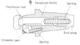
1. Remove the end plug and spring from the tensioner assembly.
2. Unlock the one-way cam by pushing it with your finger and push the tensioner rod into the tensioner body until it stops.
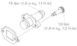
3. Install the tensioner to the cylinder and torque the bolts to the specification.
Tightening torque:
10 Nm (1.0 m-kg, 7.2 ft-lb)
4. Reinstall the spring and end plug with the gasket. Torque the end plug to the specification.
Tightening torque:
15 Nm (1.5 m-kg, 11 ft-lb)
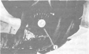
D, Ignition timing 1. Ignition timing is checked with a timing light by observing the position of the stationary pointer and the marks stamped on the timing plate.
The timing plate is marked as follows:
 .... Firing range for No. 1 (L.H.) cylinder
 ... Top Dead Center for No. 1 (L.H.>andNo.4(R.H.) cylinders
2. Connect the timing light to No. 1 (L.H.) spark plug lead wire.
3. Start the engine and keep the engine speed as specified. Use a tachometer to check the engine speed.
Specified engine speed: 1,050 r/min
4. The stationary pointer should be within the limits of " U " on the timing plate. If it exceeds the limits or does not steady, check the timing plate for tightness and/or ignition system for damage. (See "ELECTRICAL")
CAUTION
Never bend the stationary pointer.
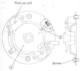
1, Timing plate 2. Stationary pointer
E. Air filter
1. Removal
a. Remove the seat.
b. Remove the fuse box.
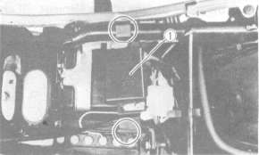
1. Fuse box
c. Remove the air filter case securing screw. Then, pull the air filter case holding plate backward.
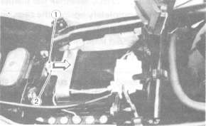
1. Securing screw 2. Holding plate
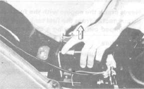
d. Pull out the air filter case.
e. Pull out the element.
1. Air filter element
2. Cleaning method
Tap the element lightly to remove most of the dust and dirt; then blow out the remaining dirt with compressed air from the inner surface of the element. If element is damaged, replace it.
3. Reassemble by reversing the removal procedure. Check whether the element is seated completely against the case.
4. The air filter element should be cleaned at the specified intervals.
CAUTION:
The engine should never be run without the air cleaner element installed; excessive piston and/or cylinder wear may result.
F. Carburetor
Never crank the engine with the fuel lines disconnected from the fuel tank. Fuel will be pumped out, creating a fjre hazard.
Idle mixture
The idle mixture is set at the factory by the use of special equipment. No attempt should be made by the dealer to change this adjustment.
Synchronization
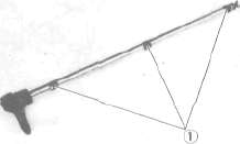
The seat must be removed and the rear of the tank elevated to gain access to the vacuum connections and synchronizing screw.
NOTE:
The valve clearances must be set properly before synchronizing the carburetors.
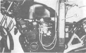
1. Remove the vacuum pipe from the carburetor manifold (No. 3 cylinder) and turn the fuel cock to "PRI."
2. Remove the rubber caps from the No. 1, 2, and 4 carburetor manifolds.
1. Rubber cap
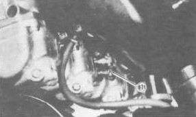
3. Remove either the left or right (but not both) blind plug at the end of the YICS (Yamaha Induction Control System) passage in the cylinder.
1. Blind plug
4. Insert the YICS shut-off tool (special tool P/No. 90890-04068) fully and flip the locking lever.
1. Shut-off tool rubber (P/No 90890-04073)
5. Connect each vacuum gauge hose to its proper carburetor.
1. Vacuum gauge
6. Start the engine and allow it to warm up for a few minutes. The warm-up is complete when the engine responds normally to the throttle opening.
7. Make sore the engine idle speed is 950 ~ 1,000 r/min. If it is not, adjust the idle speed with the throttle stop screw.
NOTE:
With the YICS shut off tool fitted, the engine speed generally drops a little. Thus, continue with the following steps at an idle speed of 950-1,000 r/min.
8. Each gauge reading will indicate the same if the carburetors are synchronized. The No. 3 carburetor has no synchronizing screw, and the other carburetors are to be synchronized to it in order, one at a time.
First, synchronize carburetor No. 1 to carburetor No. 2 by turning the No. 1 synchronizing screw until both gauges read the same.
Second, in the same way synchronize carburetor No. 4 to carburetor No. 3. Third, by adjusting No. 2 screw, watch No. 3 carburetor reading. No. 1 and No. 2 carburetors will both change to match No. 3 carburetor.
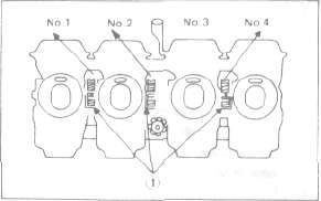
1. Synchronizing screws
9. Remove the YICS shut off tool and reinstall the blind plug.
Tightening torque:
22 Nm (2.2 m-kg, 16 ft-lb)
10. Check the idle speed. Adjust if necessary.
Idle speed adjustment
NOTE
Carburetors must be synchronized before setting the final idle speed. The idle speed adjustment is made by turning only one throttle stop screw.
1. The engine must be warmed up before setting the idle speed.
2. Set the engine idle speed by turning the throttle stop screw in (to increase engine speed) or out (to decrease engine speed).
Standard idle speed: 1,050 ± 50 rpm
1. Throttle stop screw
G. Engine oil
1. Oil level measurement
a. Place the motorcycle on its centerstand. Warm up the engine for several minutes.
NOTE:
Be sure the motorcycle is positioned straight up when checking the oil level; a slight tilt toward the side can produce false readings.
b. With the engine stopped, check the oil level through the level window located at the lower part of the light side crank case cover.
NOTE:
Wait a few minutes until the oil level settle before checking.
d. Remove the drain plug and drain the oil.
1. Maximum mark 2. Minimum mark 3. Level window
c. The oil level should be at the maximum level. If the level is lower, add sufficient oil to raise it to the maximum level.
2. Engine oil and oil filter replacement
a. Start the engine and run it a few minutes to warm it up.
b. Place an oil pan under the engine and remove the oil filler cap.
c. Remove the lower panel.

1 Lower panel
1. Drain plug
e. Remove the oil filter bolt and filter element.
1. Oil filter cover
f. Reinstall the drain plug (make sure it is tight).
Drain plug torque: 43 Nm (4.2 m-kg, 31.0 ft-lb)
g. Install the new oil filter element, new O-ring and filter cover; tighten the oil filter bolt.
Oil filter bolt torque:
15 Nm (1.5 m-kg, 11.0 ft-lb)
NOTE:
Make sure the O-ring is positioned properly.
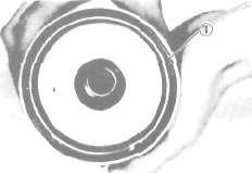
1 - Proper O-ring position
h. Add oil through the oil filler hole.
Periodic oil change:
2.5 L (2.2 Imp. qt. , 2.6US qt.) With oil filter replacement:
2.9 L (2.6 Imp qt, 3.1 US qt.) Recommended oil:
YAMALUBE 4-cycle oil or SAE
20W40 type SE motor oil
CAUTION:
Take care not to allow foreign material to enter the crankcase.
i. After replacing engine oil, and/or the oil filter, be sure to check for oil leakage. The oil indicator light should go off after oil is filled.
CAUTION:
If the indicator light flickers or remains on, the oil level switch may be damaged. Refer to ELECTRICAL for corrective action.
j. Reinstall the lower panel.
H. Final gear oil
1. Oil level measurement
a. Place the motorcycle on a level place and place it on the centerstand. The engine should be cool (at atmospheric temperature).
b. Remove the oil filler cap and check the oil level whether it is to the hole brim. If it is not up to this level, replenish oil.
CAUTION:
Take care not to allow foreign material to enter the final gear case.
1. Final gear oil 2. Correct oil Level
2. Gear oil replacement
a. Place an oil pan under the final gear case.
b. Remove the final gear oil filler cap and the drain plug, and drain the oil.
1. Final gear drain plug
WARNING:
When draining or filling, take care not to allow foreign material to enter the final gear case. Do not allow the gear oil to contact the tire and wheel.
c. Reinstall and tighten the final drain plug.
Tightening torque: 23 Nm (2.3 m-kg, 17ft-lb)
d. Fill the gear case to the specified level.
Oil capacity: Final gear case: 0.2 L (0.18 Imp. qt. , 0.21 US qt.)
Recommended oil: SAE 80 API "GL-4" Hypoid gear oil. If desired, an SAE 80W90 hypoid gear oil may be used for all conditions.
e. Reinstall the filler cap securely.
I. Compression pressure measurement
Insufficient compression pressure will result in performance loss and may indicate leaking valves or worn or damaged piston rings.
Procedure:
1. Make sure the valve clearance is correct.
2. Remove the headlight fuse from the fuse box.
3. Warm up the engine 2 ~ 3 minutes. Stop the engine.
4. Remove the all spark plugs.
5. Install a compression-check gauge.
6. Turn over the engine with the electric starter (make sure the battery is fully charged) with the battery is fully charged) with the throttle wide open until the pressure indicated on the gauge does not increase further.
Compression pressure (at sea level):
Standard 834 kPa (8.5 kg/cm2, 121 psi)
Minimum 686 kPa (7 kg/cm2, 100 psi)
Maximum 981 kPa (10 kg/cm2, 142 psi)
When cranking the engine, ground the removal spark plug wires to prevent sparking.
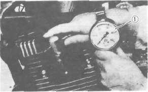
1. Compression gauge
7. If the pressure is too low, squirt a few drops of oil into the cylinder being measured. Measure compression again. If there is a higher reading than before (without oil), the piston rings may be worn or damaged. If the pressure remains the same after measuring with the oil, either or both the rings and valves may be the cause.
8. Check each cylinder. Compression pressure should not vary more than the specified value from one cylinder another.
Difference in gauge reading: Less than 98.1 kPa (1.0 kg/cm2, 14 psi)
J. Clutch adjustment
Free play adjustment
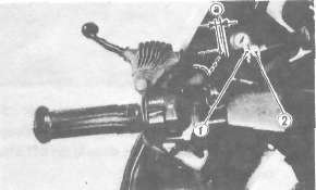
1. Locknut 2. Adjuster. 2—3 mm (0.08—0.12 in)
a. Loosen either the handle lever adjuster lockout or the cable length-adjuster lock-nut.
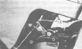
1 Locknut 2. Adjuster
b. Turn the cable length-adjuster either in or out until the proper lever free play is achieved.
- Printer-friendly version
- Log in to post comments