TCI Identification
The following is a guide to determing if a used TCI is appropriate for a given machine:
The following is a guide to determing if a used TCI is appropriate for a given machine:
This series assumes you took the carbs apart, and are trying to figure out how to put them back together again. If you haven’t taken them apart yet, it’s a good idea to skim through this first anyway. Address any questions to: xj-owners@micapeak.com, and we’ll try to talk you through it.
Pictures and text by Dwayne Verhey
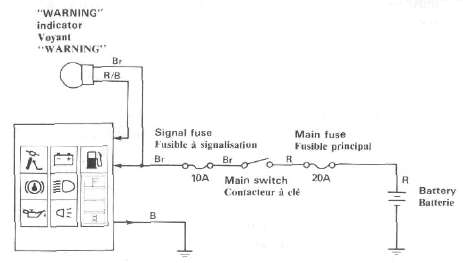
Problem: THE COMPUTERIZED MONITOR DOES NOT COME ON WITH THE MAIN SWITCH TURNED ON.
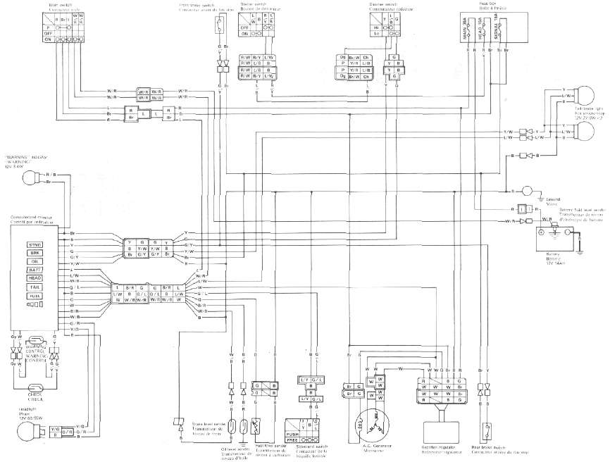
XJ750
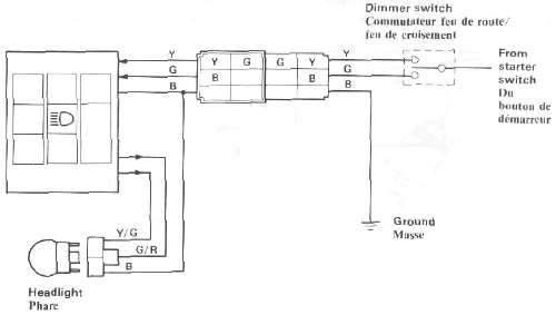
Problem: HEADLIGHT DOES NOT COME ON. (MONITOR DOES NOT LIGHT.)
Light lead connections:
HI: Yellow to Yellow/Green (or Yellow/Red)
Lo: Green to Green/Red
NOTE: On the XJ750, no lights will come on before the engine starts.
Sender locations
HTML clipboard
XJ750
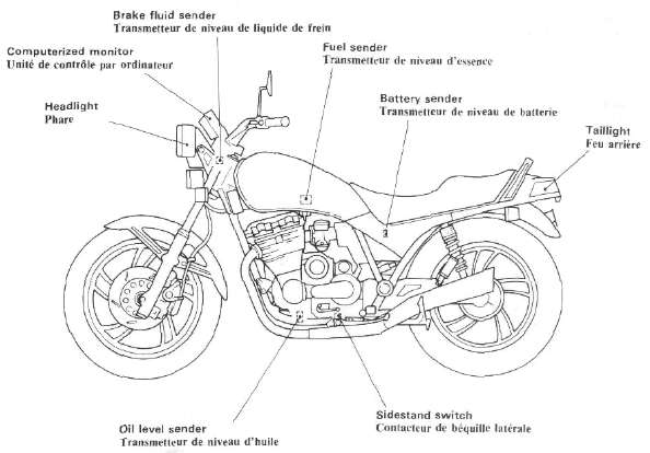
System Components
|
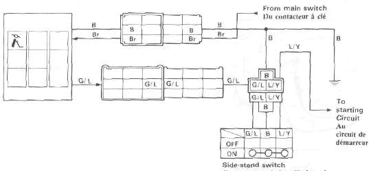
Sidestand switch |
Brake fluid level sender |
SIDESTAND MONITOR
|
*Main switch is ON. |
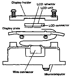
Cleaning and replacement
Use the following procedure to replace the LCD unit or the microcomputer unit.
1. Remove the headlight lens and the two headlight-body holding bolts. This will give you easy access to the instrument-panel holding nuts.
ANTI-DIVE SYSTEM
Normal oil flow -- no brakes applied.