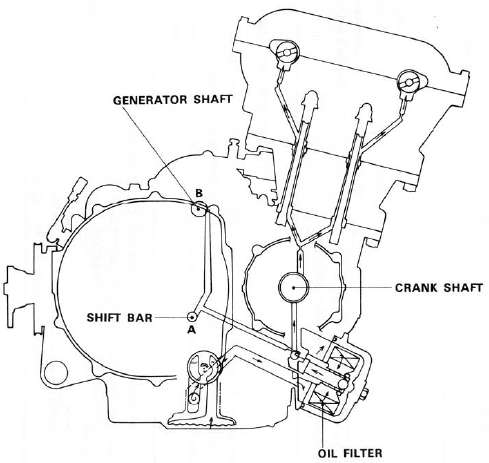
Lubrication Diagrams
LUBRICATION DIAGRAMS
- Read more about Lubrication Diagrams
- Log in to post comments
LUBRICATION DIAGRAMS
L. Transmission
1. Inspect each shift fork for signs of galling on gear contact surfaces. Check for bending. Make sure each fork slides freely on its guide bar.
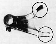
2. Roll the guide bar across a surface place. If the bar is bent, replace.
I. Crankshaft
1. Crankshaft run-out
Support the crankshaft at both ends on V-blocks. Measure the amount of crankshaft run-out on the main bearing journals with a dial gauge while rotating crankshaft.
Run-out limit: 0.040 mm (0.0016 in)
If run-out exceeds limit, replace crankshaft.
2. Inspection of bearings
1. AC Generator
2. Rectifier/Regulator
3. Main Switch
4. Main Fuse
5. Battery
B. A.C. Generator
1. Checking method.
J. Oil Pump
1. Check the clearance between housing and outer rotor.
Standard clearance: 0.09 ~ 0.15 mm (0.0035 ~ 0.0059 in)
2. Check the clearance between outer rotor and inner rotor.
Standard clearance: 0.12 mm (0.005 in) or less
3. Check the plunger for scratches and wear.
CHAPTER 4. CARBURETION
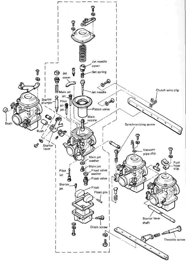
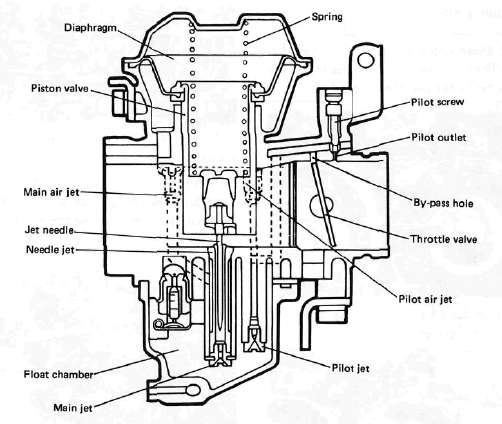
CARBURETOR
A. Section View
B. Specifications
|
Main jet |
#120 |
CHAPTER 2. PERIODIC INSPECTIONS AND ADJUSTMENTS
INTRODUCTION