Specifications
SPECIFICATIONS
General Specifications
|
|
XJ650G |
|
Basic color Dimensions: Overall length |
- Read more about Specifications
- Log in to post comments
SPECIFICATIONS
General Specifications
|
|
XJ650G |
|
Basic color Dimensions: Overall length |
ELECTRICAL
A. Battery
1. The fluid level should be between the upper and lower level marks. Use only distilled water if refilling is necessary.
CAUTION:
Normal tap water contains minerals which are harmful to a battery; therefore, refill only with distilled water.
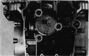
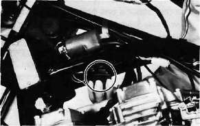
H. Oil Pump Removal and Disassembly
1. Remove the strainer cover. Note the wire harness clip position.
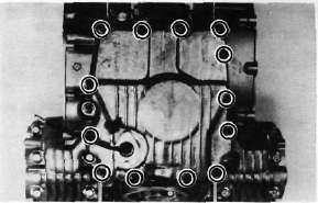
2. Remove the oil pump securing bolts and remove the sprocket cover and oil pump assembly.
8. A.C. Generator
a. Install the rotor onto the shaft and tighten the bolt using the rotor holding tool (special tool) as shown.
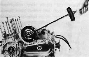
1. Rotor holding tool
Tightening torque: 5.5 m-kg (39.8 ft-lb)
b. Install the stator coil assembly onto the crankcase and align the grooves on the stator core with the bolt holes on the crankcase.
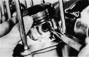
C. Piston
1. Mark each piston to aid in reassembly.
2. Place a clean towel or rag into the crank-case to keep circlips and material from falling into the engine.
3. Remove piston pin clips, piston pins, and pistons.
D. Pick-up Coil Assembly
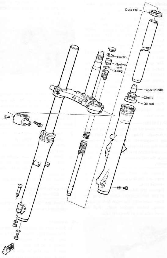
FRONT FORK
A. Removal and Disassembly
WARNING:
Securely support the motorcycle so there is no danger of it falling over.
ENGINE
A. Valve Clearance Adjustment
NOTE:
Valve clearance must be measured with the engine and at room temperature.
1. Remove the seat and fuel tank.
2. Remove the horn, flasher relay, and spark plug lead wires.
12. Cylinder head and Cam shafts
a. Install the new cylinder head gasket. Install the dowel pins and "O-rings". Locate the cam chain cavity cylinder seal with the tabs down.
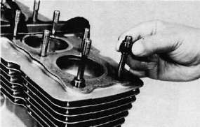
b. Install the cylinder head onto the cylinder. Pull the cam chain through the cylinder head as it is installed. Tie the cam chain so that it does not fall into the crankcase.
CONSUMER INFORMATION
Notice
The information presented represents results obtainable by skilled drivers under controlled road and vehicle conditions, and the information may not be correct under other conditions.
STOPPING DISTANCE
P. Middle Gear
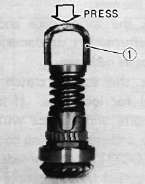
1. Damper disassembly
NOTE:
Disassembly of the middle gear damper requires the damper compressor (special tool) and a hydraulic press.
a. Place the middle drive shaft in a press with the damper compressor (special tool) in place as shown.