Chapter 5. Chassis
Chapter 5. ChassisCable and Fittings
Cable and FittingsA. Cable maintenance
NOTE:
See Maintenance and Lubrication intervals charts. Cable maintenance is primarily concerned with preventing deterioration through rust and weathering and providing proper lubrication to allow the cable to move freely within its housing. Cable removal is straight forward and uncomplicated. Removal will not be discussed within this section.
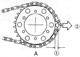
A. Checking for excessively 1.1/2 tooth
worn chain 2. Pull
WARNING:
Cable routing is very important. For details of cable routing, see the cable routing diagrams at the end of this manual. Improperly routed or adjusted cables may make the motorcycle unsafe for operation.
1. Remove the cable.
2. Check for free movement of cable within its housing. If movement is obstructed, check for fraying or kinking of the cable strands. If damage is evident, replace the cable assembly.
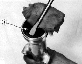
3. To lubricate the cable, hold it in a vertical position. Apply lubricant to the uppermost end of cable. Leave it in the vertical position until lubricant appears at the bottom. Allow any excess to drain and reinstall the cable.
NOTE:
Choice of lubricant depends upon conditions and preferences. However, a semi-drying chain and cable lubricant will perform adequately under most conditions.
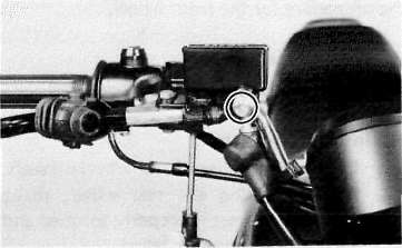
B. Throttle maintenance
1. Remove the Phillips head screws from throttle housing assembly and separate the two halves of housing.
2. Disconnect the cable end from the throttle grip assembly and remove the grip assembly.
3. Wash all parts in a mild solvent and check all contact surfaces for burrs or other damage. (Also clean and inspect right-hand end of the handlebar.)
4. Lubricate all contact surfaces with a light coat of lithium soap base grease and reassemble.
NOTE:
Tighten the housing screws evenly to maintain an even gap between the two halves.
5. Check for smooth throttle operation and quick spring return when released and make certain that the housing does not rotate on the handlebar.
Front Wheel
Front WheelA. Removal
1. Place the motorcycle on the center stand.
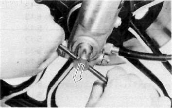
2. Remove the cotter pin and wheel axle nut.
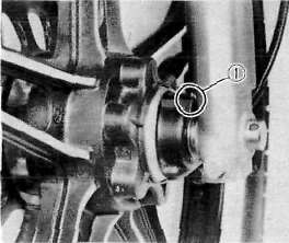
3. Loosen the pinch bolt securing the axle.

1. Pinch bolt
4. Remove the axle shaft and the front wheel. In this case, make sure the motorcycle is properly supported.
NOTE:
Do not depress the brake lever when the wheel is off the motorcycle as the brake pads will be forced to shut.
B. Front axle inspection
Remove any corrosion from the axle with fine emery cloth. Place the axle on a surface plate and check for bends. If bent, replace axle. Do not attempt to straighten a bent axle.
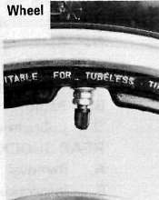
C. Front wheel inspection
This motorcycle is equipped with aluminum wheels designed to be compatible with either tube or tubeless tires.
Tubeless tires are installed as standard equipment.
WARNING:
Do not attempt to use tubeless tires on a wheel designed for use only with tube-type tires. Tire failure and personal injury may results from sudden deflation.
Tube-type Wheel > Tube-type Tires Only
Tubeless-type Wheel > Tube-type or Tubeless tires
WARNING:
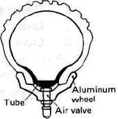
When using tube-type tires, be sure to install the proper tube also.
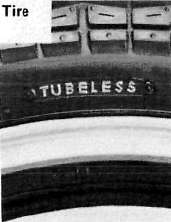
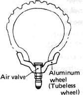
Tubeless Tire
Tube-type Tire
Refer to "Tubeless Tire and Aluminum Wheel Manual" for the proper tubeless and aluminum wheel servicing.
1. Check for cracks, bends or warpage of wheels. If a wheel is deformed or cracked, it must be replaced.
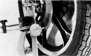
2. Check wheel run-out. If the deflection exceeds the tolerance below, check the wheel bearings or replace the wheel as required.
Rim-run-out limits:
Vertical - 2 mm (0.079 in) Lateral - 2 mm (0.079 in)
3. Check wheel balance. Rotate the wheel lightly several times and observe resting position. If the wheel is not statically balanced, it will come to rest at the same position each time. Install an appropriate balance weight at lightest position (at top).
NOTE:
The wheel should be balanced with the brake disc installed.
4. After installing a tire, ride conservatively to allow the tire to seat itself on the rim properly. Failure to allow proper seating may cause tire failure resulting in damage to the motorcycle and injury to the rider.
5. After repairing or replacing a tire, check to be sure the valve stem lock nut is securely fastened. If not, torque it as specified.
Tightening torque: 0.15 m-kg (1.1 ft-lb)
D. Replacing wheel bearings
If the bearings allow play in the wheel hub or if wheel does not turn smoothly, replace the bearings as follows:
1. Clean the outside of the wheel hub.
2. Drive the bearing out by pushing the spacer aside and tapping around the perimeter of the bearing inner race with a soft metal drift pin and hammer. The spacer "floats" between the bearings. Both bearings can be removed in this manner.
WARNING:
Eye protection is recommended when using striking tools.
3. To install the wheel bearing, reverse the above sequence. Use a socket that matches the outside race of the bearing as a tool to drive in the bearing.
CAUTION:
Do not strike the center race or balls of the bearing. Contact should be made only with the outer race.
E. Installing front wheel
When installing the front wheel, reverse the removal procedure. Note the following points:
1. Lightly grease the lips of the front wheel oil seals and the gear teeth of speedometer drive and driven gears. Use lightweight lithium soap base grease.
2. Make sure the projecting portion (torque stopper) of the speedometer housing is positioned correctly.
1. Torque stopper
3. Tighten the axle nut and install a new cotter pin.
Axle nut torque: 10.5 m-kg (76.0 ft-lb)
4. Before tightening the pinch bolt, compress the front forks several times to make sure of proper fork operation.
5. Tighten the axle pinch bolt.
Axle pinch bolt torque: 2.0 m-kg (14.5 ft-lb)
Front Brake
Front Brake
CAUTION:
Disc brake components rarely require disassembly. Do not disassemble components unless absolutely necessary. If any hydraulic connection in the system is opened, the entire system should be disassembled, drained, cleaned and then properly filled and bled upon reassembly. Do not use solvents on brake internal components. Solvents will cause seals to swell and distort. Use only clean brake fluid for cleaning. Use care with brake fluid. Brake fluid is injurious to eyes and will damage painted surfaces and plastic parts.
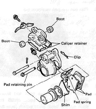
A. Caliper pad replacement
It is not necessary to disassemble the brake caliper and brake hose to replace the brake pads.
1. Remove the front fender and front wheel.
2. Unhook the pad retaining pin clip and remove the clip.
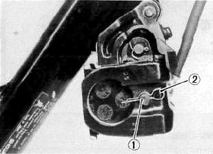
1. Pad retaining pin 2. Clip
3. Pull out the pad retaining pin.
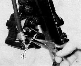
1. Pad retaining pin
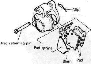
4. Remove the pads.
5. Install the new brake pads and shims. Before installing the pads, install the shim on the back plate which faces the caliper piston, as shown. Also replace the following parts if pad replacement is required.
a. Pad spring
b. Shim
c. Pad retaining pin
d. Clip
NOTE:
Replace the pads as a set if either is found to be worn to the wear limit.
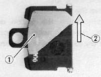
1. Shim 2. Disc rotating direction
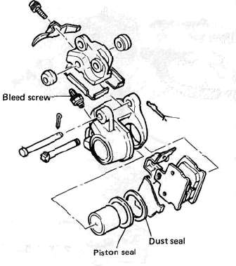
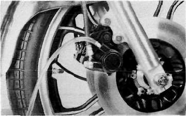
B. Caliper disassembly
1. Remove the brake hose from the caliper. Allow the caliper assembly to drain into a container.
2. Place the open hose end into the container and pump the old fluid out of the master cylinder.
3. Remove the pad spring, shim, pad retaining pin, clip and pads.
4. Remove the brake caliper holding bolt from the front fork.
5. Remove the dust seal.
6. Carefully force the piston out of the caliper cylinder with compressed air. Never try to pry out the piston.
WARNING:
Cover the piston with a rag. Use care so that piston does not cause injury as it is expelled from the cylinder.
7. Remove the piston seal.
C. Master cylinder disassembly
1. Remove the brake light switch.
2. Remove the brake hose.
3. Remove the brake lever and spring.
4. Remove the master cylinder from the handlebar. Remove the cap and drain the remaining fluid.
5. Remove the master cylinder dust boot.
6. Remove the snap ring.
7. Remove the master cylinder cup assembly. Note that the cylinder cups are installed with the larger diameter (lips) inserted first.
D. Brake inspection and repair
Recommended Brake Component Replacement Schedule:
Brake pads; As required
Piston seal, dust seal; Every two years
Brake hoses; Every four years
Brake fluid; Replace only when brakes are disassembled
1. Replace the caliper piston if it is scratched.
2. Replace any brake pad worn beyond limits. Always replace the brake pads as a set.
See Caliper Pad Replacement procedure for a listing of the parts to be replaced when pads are replaced.
Wear limit: 4.0 mm (0.16 in)
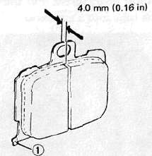
1. Wear indicator
3. Replace piston and dust seals if damaged. Replace seals every two years.
4. Inspect master cylinder body. Replace if scratched. Clean all passages with new brake fluid.
5. Inspect the brake hoses. Replace every four years or immediately if cracked, frayed, or damaged.
6. Check for wear and deflection of disc.
Maximum deflection: 0.15 mm (0.006 in)
Minimum disc thickness: 4.5 mm (0.18 in)
If disc is worn beyond minimum thickness or deflection exceeds specified amount, replace disc.
E. Brake reassembly
1. Caliper reassembly
All internal parts should be cleaned in new brake fluid only. Internal parts should be lubricated with brake fluid when installed. Replace the following parts whenever a caliper is disassembled.
Bleed screw and rubber cap
Piston seal
Dust seal
a. Install the piston seal and piston.
b. Install the pads.
2. Install the caliper assembly on the front fork.
Caliper holding bolt torque: 4.5 m-kg (32.5 ft-lb)
4. Attach the brake hoses.
Brake hose torque: 2.6 m-kg (19.0 ft-lb)
5. Brake disc assembly
If brake disc has been removed from hub or is loose, tighten bolts. Use new locking washers and bend over locking
tabs after bolts are tightened.
Disc bolt torque: 2.0 m-kg (14.5 ft-lb)
6. Master cylinder reasembly
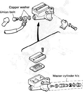
Reassemble master cylinder as shown in illustration.
Brake hose torque: (all brake union bolts) 2.6 m-kg (19.0 ft-lb)
7. Air bleeding
WARNING:
If the brake system is disassembled or if any brake hose has been loosened or removed, the brake system must be bled to remove air from the brake fluid. If the brake fluid level is very low or brake operation is incorrect, bleed the brake system. Failure to bleed the brake system properly can result in a dangerous loss of braking performance.
a. Add proper brake fluid to the reservoir. Install the diaphragm, being careful not to spill or overflow the reservoir.
b. Connect the clear plastic tube of 4.5 mm (3/16 in) inside diameter tightly to the caliper bleed screw. Put the other end of the tube into a container.
c. Slowly apply the brake lever several times. Pull in the lever. Hold the lever in "on" position. Loosen the bleed screw. Allow the lever to travel slowly toward its limit. When the limit is reached, tighten bleed screw. Then release the lever.
d. Repeat step "c" procedure until all air bubbles are removed from system.
NOTE:
If bleeding is difficult, it may be necessary to let the brake fluid system stabilize for a few hours. Repeat the bleeding procedure when the tiny bubbles in the system settle out.
Front Forks
Front Forks
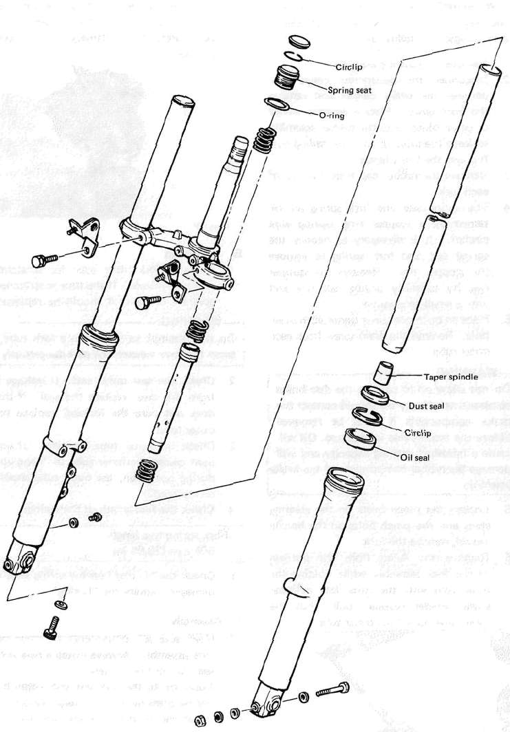
A. Removal and disassembly
WARNING:
Securely support the motorcycle so there is no danger of it falling over.
1. Remove the cowling assembly.
2. Disconnect the speedometer cable. Disconnect the brake caliper and remove the front wheel. Place a wooden wedge or other object into the caliper assembly to keep the brake pads from falling out. Remove the front fender.
3. Remove the rubber cap from the top of each fork.
4. The spring seat and fork spring are retained by a stopper ring (spring wire circlip). It is necessary to depress the spring seat and fork spring to remove the stopper ring. Remove the stopper ring by carefully prying out one end with a small screwdriver.
5. Place an open container under each drain hole. Remove the drain screw from each outer tube.
WARNING:
Do not allow oil to contact the disc brake components. If any oil should contact the brake components it must be removed before the motorcycle is operated. Oil will cause diminished braking capacity and will damage the rubber components of the brake assembly.
5. Loosen the pinch bolts on the steering stem and the pinch bolts on the handle crown, remove the fork.
6. Remove the Allen from the bottom of the fork assembly while holding the inner tube with the front fork cylinder comp. holder (special tool). Pull the inner tube out of the outer tube.
7. To remove the fork seal. Pry out the dust seal and remove the spring clip over the oil seal. Pry out the oil seal, being very careful to not damage the fork tube surfaces.
1. Dust seal
B. Inspection
1. Examine fork inner tube for scratches and straightness. If the tube is scratched severely or bent, it should be replaced.
WARNING:
Do not attempt to straighten a fork tube, since this may weaken the part dangerously.
2. Check the seal outer seat. If leakage is from this area, replace the seal. If this does not cure the leakage, replace the outer tube.
3. Check the outer tube for dents. If any dent causes the inner tube to "hang up" during operation, the outer tube should be replaced.
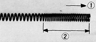
4. Check the free length of the springs.
Fork spring free length: 508 mm (20.00 in)
5. Check the "O-ring" on the spring seat. If damaged, replace the "O-ring",
C. Assembly
1. Make sure all components are clean before assembly. Always install a new fork seal. Do not re-use seal.
2. Apply oil to the fork seal and install the seal by pressing in with a large socket. Install the retaining clip and dust seal.
3. Install the inner tube into the outer tube. Install and tighten alien bolt and washer. The assembly procedure is the reverse of the disassembly procedure.
NOTE:
When installing the fork springs, the greater pitch should be at the bottom. The main fork spring has a small coil diameter at the bottom.
4. Reinstall the spring seat.
CAUTION:
Always use a new stopper ring (spring wire circlip).
1. Top 2. Small pitch
Steering Head
Steering HeadSTEERING HEAD
A. Adjustment
Refer to "D. Reassembly" for steering head adjustment procedure.
B. Removal
1. Remove the cowling assembly, meters, horn, front wheel, front forks, handlebar cover and handlebars.
2. Remove the front brake pipe junction.
3. Remove the stem bolt and steering crown.
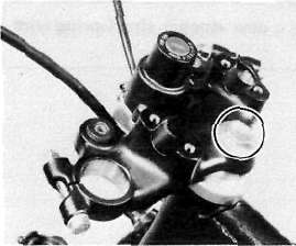
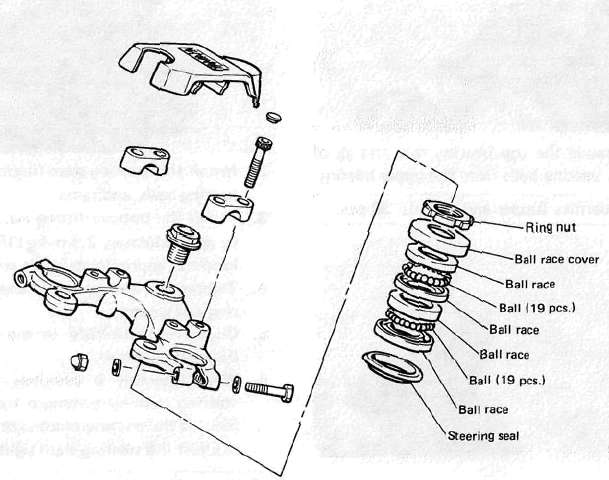
4. Support the steering stem (under bracket) and remove the fitting nut (ring nut).
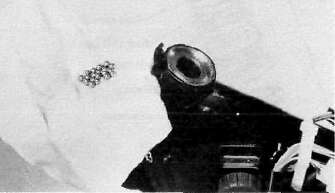
5. Remove the top bearing race and all of the bearing balls from the upper bearing.
Ball quantity (upper and lower): 38 pcs.
C. Inspection
1. Wash the bearings in solvent.
2. Inspect the bearings for pitting or other damage. Replace the bearings if pitted or damaged. Replace the races when bearing balls are replaced.
3. Clean and inspect the bearing races. Spin the bearings by hand. If the bearings are not smooth in their operation in the races, replace bearing balls and races.
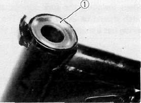
I. Bearing race
D. Reassembly
1. Grease the bearings and races with wheel bearing grease.
2. Install the steering stem (under bracket), bearing balls, and races.
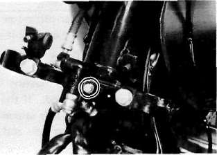
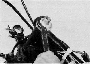
3. Install the bottom fitting nut. Tighten it to approximately 2.5 m-kg (18 ft-lb) and loosen it approximately 1/4 turn.
4. Tighten the fitting nut securely with the ring nut wrench.
5. Continue reassembly in the reverse of disassembly order.
6. When assembly is complete, check the steering stem by turning it from lock to lock. If there is any binding or looseness, readjust the steering stem tightness.
Steering stem bolt torque: 5.4 m-kg (30.0 ft-lb)
Rear Wheel
Rear WheelA. Removal
1. Place the motorcycle on the center stand.
2. Remove the tension bar and the brake rod from the brake shoe plate. The tension bar can be removed by removing the cotter pin and nut from the tension bar bolt. The brake rod can be removed by removing the adjuster.
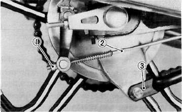
1. Adjuster 3. Tension bar
2. Brake rod
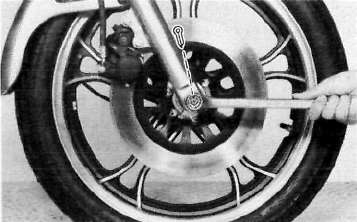
3. Remove the axle nut cotter pin and loosen the axle nut.
4. Loosen the adjusting bolt and let the chain puller down as in the photo.
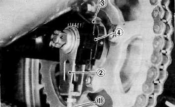
1. Adjusting bolt 2. Chain puller 3. Pinch bolt 4. Rear arm end
5. Remove the pinch bolt and chain puller attachment.
6. Push the rear wheel forward and remove the drive chain.
7. The rear wheel can be removed by pulling the wheel axle, backward.
B. Checking brake shoe wear
1. Measure the outside diameter at the brake shoes with slide calipers.
Front brake shoe diameter: 160 mm (6.30 in)
Replacement limit: 156 mm min. (6.14 in)
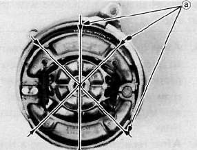
a. Measuring points
2. Remove any glazed areas from the brake shoes using coarse sand paper.
C. Brake drum
Oil or scratches on the inner surface or the brake drum will impair braking performance or result in abnormal noises.Remove oil by wiping with a rag soaked in lacquer thinner or solvent. Remove scratches by lightly and evenly polishing with emery cloth.
D. Brake shoe plate
Remove the camshaft and grease. If the cam face is worn, replace.
NOTE
Before removing the cam lever, put a match mark on the cam lever and camshaft to indicate their positions for easy assembly.
E. Rear axle inspection
(See Front wheel axle inspection procedure.)
F. Replacing wheel bearings
Rear wheel bearing replacement is similar to the procedure for the front wheel.
G. Rear wheel inspection
(See Front wheel. Inspection procedures)
H. Installing rear wheel
1. Lightly grease lips of rear wheel oil seals.
2. After installing the rear wheel, make sure the axle nut is properly torqued and a new cotter pin is installed.
CAUTION:
Always use a new cotter pin on the axle nut.
Tightening torque: Axle nut: 10.5 m-kg (76.0 ft-lb)
3. Adjust the drive chain.
4. Adjust the rear brake.
Rear Shock, Drive chain and Sprocket
Rear Shock, Drive chain and SprocketA. Removal
1. Remove one (1) rear shock absorber at at time, inspect and reinstall before removing the other.
B. Inspection
1. Check the rod. If it is bent or damaged, replace the shock absorber.
2. Check for oil leakage. If oil leakage is evident, replace the shock absorber.
3. Operate shock absorber rod to check damping. There should be no noticeable damping as the shock extends.
4. Install the shock absorber on the motorcycle.
Tightening torque:
3.0 m-kg (21.5 ft-lb)
DRIVE CHAIN AND SPROCKETS
NOTE:
Please refer to General maintenance and Lubrication charts for additional information.
A. Drive sprocket
With the left crankcase cover removed proceed as follows:
1. Remove the sprocket securing bolts. Remove the holder plate and drive sprocket.
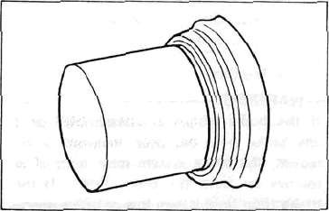
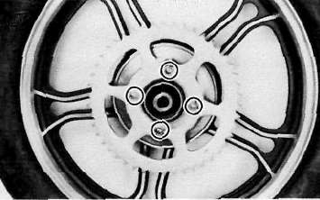
2. Check sprocket wear. Replace if wear decreases tooth width as shown.
3. Replace if tooth wear shows a pattern such as that in the illustration, or as precaution and common sense dictate.
4. Tighten the securing bolts.
Drive sprocket securing bolt torque:
1.0 m-kg (7.2 ft-lb)
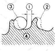
1,1/4 tooth 2, Correct 3. Roller 4. Sprocket
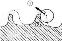
1. Slip off 2. Bent teeth
B. Driven sprocket
With the rear wheel removed, proceed as
follows:
1. Using a blunt chisel, flatten the securing nuts lock washer tabs.
Remove the securing nuts. Remove the lock washers and sprocket.
2. Check the sprocket wear using procedures for the drive sprocket.
3. Check the sprocket to see that it runs true. If bent, replace.
4. During reassembly, make sure that sprocket and sprocket seat are clean. Tighten the securing nuts in a crisscross pattern.
Bend the tabs of the lock washers fully against the securing nut flats.
Driven sprocket securing nut torque: 6.2 m-kg (45.0 ft-lb)
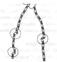
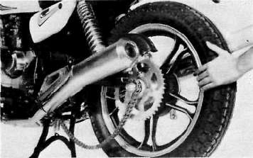
C. Chain inspection
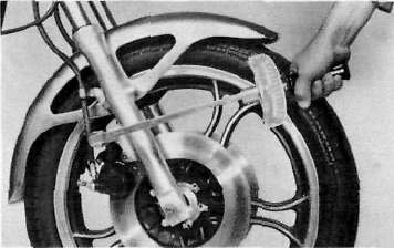
1. With the chain installed on the motorcycle, excessive wear may be roughly determined by attempting to pull the chain away from the rear sprocket. If the chain will lift away more than one-half the length of the sprocket teeth, remove and inspect.
If any portion of the chain shows signs of damage, or if either sprocket shows signs of excessive wear, remove the inspect.
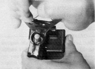
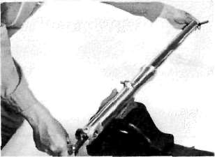
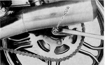
2. Check the chain for stiffness. Hold as illustrated. If stiff, soak in solvent solution, clean with wire brush, dry with high pressure air. Oil chain thoroughly and attempt to work out kinks. If still stiff, replace chain.
3. Check the side plate for damage. Check to see if excessive play exists in pins and rollers. Check for damaged rollers. Replace as required.
D. Chain maintenance
The chain should be lubricated according to the recommendations given in the General Maintenance/Lubrication charts, or more often if possible. (Preferably after every use.)
1. Wipe off dirt with shop rag. If accumulation is severe, use wire brush, than rag.
2. Apply lubricant between roller and side plates on both inside and outside of chain. Don't skip a portion as this will cause uneven wear. Apply thoroughly. Wipe off excess.
Recommended lubricant:
Yamaha Chain and Cable Lube or SAE 10W/30 motor oil.
3. Periodically, remove the chain. Wipe and/or brush excess dirt off. Blow off with high pressure air.
4. Soap chain in solvent, brushing off remaining dirt. Dry with high pressure air. Lubricate thoroughly to make sure lubricant penetrates. Wipe off excess. Reinstall.
Swing Arm
Swing ArmSWING ARM
A. Inspection
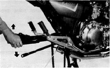
1, Free play inspection
Remove the rear wheel and both shock absorbers. Grasp the swing arm and try to move it from side to side as shown.
Swing arm free play: 1.0 mm (0.04 in)
2. If the free play is excessive, remove the swing arm and replace the swing arm bushes.
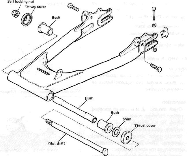
B. Removal
1. Remove the nut on swing arm pivot shaft and tap out the shaft with a long aluminum or brass rod.
NOTE:
Carefully remove the arm while noting the location of bushes and shims. They must be reinstalled in the same positions.
2. Tap out old bushes from each side of the pivot using the long rod.
3. Install the new bushes using a press.
NOTE:
Do not hammer in the bushes when installing; it may result in breakage to the bushes.
4. For reinstallation, reverse the removal procedure.
Pivot shaft tightening torque: 9.0 m-kg (65.0 ft-ib)
C. Lubrication
1. This model is equipped with the oilless bushes, but it is recommended to apply grease on the bushes lightly.
Recommended lubricant: Lithium soap base grease
2. Wipe off excess grease.