Chassis
ChassisBrakes
Brakes1. Brake adjustment
a. Front brake lever free play adjustment
The brake can be adjusted by simply adjusting the free play of the brake lever. The piston in the caliper moves forward as the brake pad wears out, automatically adjusting the clearance betweenthe brake pads and brake disc.
CAUTION:
Proper lever free play is essential to avoid excessive brake drag.
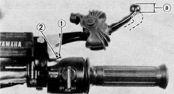
1. Adjuster 2. Lock nut a. 5 — 8 mm (0,2 ~ 0.3 in)
1) Loosen the adjuster lock nut on the brake lever.
2) Turn the adjuster so that the brake lever movement at the lever end is 5 ~ 8 mm {0.2 ~ 0.3 in) before the adjuster contacts the master cylinder piston.
3) After adjusting, tighten the lock nut.
b. Rear brake pedal height adjustment
1) Loosen the adjuster lock nut (for pedal height).
2) By turning the adjuster bolt clockwise or counterclockwise, adjust the brake pedal position so that its top end is approximately 20 mm (0.78 in) below the foot rest top end.
3) Secure the adjuster lock nut.
WARNING:
After adjusting the pedal height, the brake pedal free play should be adjusted.
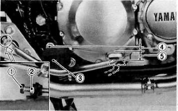
1. Adjuster bolt 3. Footrest
(for pedal height) 4. Pedal height 20 mm (0.8 in)
2. Lock nut 5. Free play 20 — 30 mm (0.8—1.2 in)
c. Rear brake pedal free play adjustment
Turn the adjuster on the brake rod clockwise or counterclockwise to provide the brake pedal end with a free play of 20— 30 mm (0.8- 1.2 in).
NOTE:
Check to see whether or not the brake light operates correctly after adjusting.
2. Front brake pad and rear brake shoe check
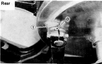
a. Front brake pad
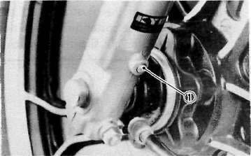
To check, look at the pad wear indicator in back of the caliper. If any pad is worn to the wear limit, replace both the pads in the caliper. Front
1. Wear indicator
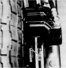
b. Rear brake shoe
To check, see the wear indicator position while depressing the brake pedal. If the indicator reaches to the wear limit line, replace the shoes.
1. Wear limit 2, Wear indicator
3. Brake fluid
Insufficient brake fluid may allow air to enter the brake system, possibly causing the brake to become ineffective. Check the brake fluid level and replenish when necessary observing these precautions:
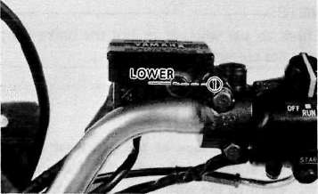
1. Lower level
a. Use only the designated quality brake fluid; otherwise, the rubber seals may deteriorate, causing leakage and poor brake performance.
Recommended brake fluid: DOT#3
b. Refill with the same type and brand of brake fluid; mixing fluids may result in a harmful chemical reaction and lead to poor performance.
c. Be careful that water or other contamination does not enter the master cylinder when refilling. Water will significantly lower the boiling point and may result in vapor lock.
d. Brake fluid may erode painted surfaces or plastic parts. Always clean up spilled fluid immediately.
Drive Chain and Wheels
Drive Chain and WheelsDrive chain
1. Drive chain tension check
NOTE:
Before checking and/or adjusting, rotate the rear wheel through several revolutions and check the tension several times to find the tightest point. Check and/or adjust chain tension with rear wheel in this "tight chain" position.
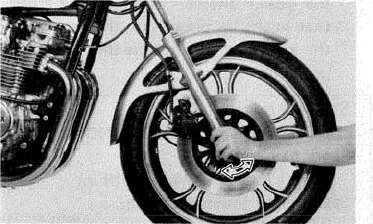
Inspect the drive chain with the center stand put up. Check the tension at the position shown in the illustration. The normal vertical deflection is approximately 35- 40 mm (1.4 ~ 1.6 in). If the deflection exceeds 35 ~ 40 mm (1.4~1.6 in) adjust the chain tension.
a. 35*^40 mm (1.4**-1.6 in
2. Drive chain tension adjustment
1. Loosen the rear brake adjuster.
2. Remove the cotter pin of the rear wheel axle nut with pliers.
3. Loosen the rear wheel axle nut.
4. Loosen the adjust bolt lock nuts on each side. To tighten the chain turn chain puller adjust bolts clockwise. To loosen the chain turn adjust bolts counterclockwise and push wheel forward. Turn each bolt exactly the same amount to maintain correct axle alignment (There are marks on each side of rear arm and on each chain puller; use them to check for proper alignment).
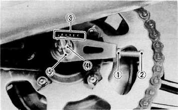
1. Lock nut 2. Adjuster 3. Marks for align 4. Rear wheel axle nut 5. Cotter pin
5. After adjusting, be sure to tighten the lock nuts and the rear wheel axle nut.
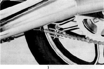
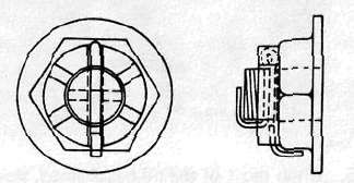
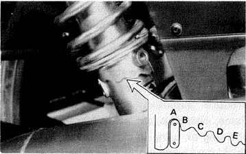
6. Insert the cotter pin into the rear wheel axle nut and bend the end of the cotter pin as shown in the illustration (if the nut notch and the cotter pin hole do not match tighten the nut slightly to match).
CAUTION:
Always use a new cotter pin on the rear axle nut.
NOTE:
Excessive chain tension will overload the engine and other vital parts; keep the tension within the specified limits.
7. In the final step, adjust the play in the brake pedal.
3. Drive chain lubrication The chain consists of many parts which work against each other. If the chain is not maintained properly, it will wear out rapidly. Without lubrication the chain could wear out within 500 km (300 mi), therefore, form the habit of periodically servicing the chain. This service is especially necessary when riding in dusty conditions.
1. Use YAMAHA CHAIN/CABLE LUBE or any of the many brands of spray type chain lubricant. First, remove dirt and mud from the chain with a brush or cloth and the spray the lubricant between both rows of side plates andon all center rollers. This should be performed every 500 km (300 mi).
2. To clean the entire chain, first remove the chain from the motorcycle, dip it in solvent and clean out as much dirt as possible. Then take the chain out of the solvent and dry it. After drying lubricate the chain to prevent the formation of rust.
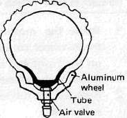
Tubeless tires and aluminum wheels
This motorcycle is equipped with aluminum wheels designed to be compatible with either tube or tubeless tires. Tubeless tires are installed as standard equipment.
WARNING:
Do not attempt to use tubeless tires on a wheel designed for use only with tube-type tires. Tire failure and personal injury may results from sudden deflation.
Tube-type Wheel — Tube-type tires only
Tubeless-type Wheel — Tube-type or Tubeless tires When using tube-type tires, be sure to install the proper tube also.
Tubeless tire
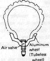
Tube-type tire
To insure maximum performance, long service, and safe operation, note the following precautions:
1. Check tire pressure, before riding, adjust as necessary.
2. Before operation, always check the tire surfaces for wear and/or damage; look for cracks, glass, nails, metal fragments, stones, etc. Correct any such hazard before riding.
3. Always inspect the aluminum wheels before a ride. Place the motorcycle on the center stand and check for cracks, bends or warpage of the wheels. Do not attempt even small repairs to the wheel. If a wheel is deformed or cracked, it must be replaced.
4. Tires and wheels should be balanced whenever either one is changed or replaced. Failure to have a wheel assembly balanced can result in poor performance, adverse handling characteristics, and shortened tire life.
5. After installing a tire, ride conservatively to allow the tire to seat itself on the rim properly. Failure to allow proper seating may cause tire failure resulting in damage to the motorcycle and injury to the rider.
6. After repairing or replacing a tire, check to be sure the valve stem lock nut is securely fastened. If not, torque it as specified.
Tightening torque: 0.15 m-kg (1.1 ft-lb)
Fuel Petcock
Fuel Petcock
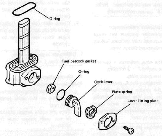
If the fuel petcock is
leaking or excessively contaminated, it should be removed from the fuel
tank and inspected.
1.
Remove the fuel tank and position it so that fuel will not spill when
the petcock is removed.
2.
Remove the petcock and inspect the filter screen. Replace the filter if
seriously contaminated.
3.
Remove the screws on the front and rear of the petcock and remove
the plate, gasket, lever, and diaphragm.
4.
Inspect all components and
replace any that are damaged. If the diaphragm is in any way damaged,
or the petcock body gasket surfaces scratched or corroded, the petcock
assembly must be replaced. If there is abrasive damage to any
component, the fuel tank must be drained and flushed.
5.
Reassemble the petcock and install it on the fuel tank.
Lubrication Points
Lubrication PointsCable inspection and lubrication
WARNING:
Damage to the outer housing of the various cables, may cause corrosion and often free movement will be obstructed. An unsafe condition may result so replace such cables as soon as possible.
1. If the inner cables do not operate smoothly, lubricate or replace them.
Recommended lubricant:
Yamaha Chain and Cable Lube or
SAE 10W/30 motor oil
I. Throttle cable and grip lubrication
The throttle twist grip assembly should be greased when the cable is lubricated, since the grip must be removed to get at the end of the throttle cable. Two screws clamp the throttle housing to the handlebar. Once these two are removed, the end of the cable can be held high to pour in several drops of lubricant. With the throttle grip disassembled, coat the metal surface of the grip assembly with a suitable all-purpose grease to cut down friction.
Brake and change pedal/brake and clutch levers
Lubricate the pivoting parts of each lever and pedal.
Recommended lubricant:
Yamaha Chain and Cable Lube or SAE 10W/30 motor oil
Center and side stand pivots
Lubricate the center and side stands at their pivot points.
Recommended lubricants:
Yamaha Chain and Cable Lube or SAE 10W/30 motor oil
Suspension and Steering
Suspension and SteeringFront fork oil change
WARNING:
Securely support the motorcycle so there is no danger of it falling over.
1. Raise the motorcycle or remove the front wheel so that there is no weight on the front end of the motorcycle. Remove the handlebar if necessary.
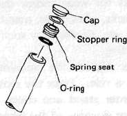
2. Remove the rubber cap from the top of each fork.
3. The spring seat and fork spring are retained by a stopper ring (spring wire circlip). it is necessary to depress the spring seat and fork spring to remove the stopper ring. Remove the stopper ring by carefully prying out one end with a small screwdriver,
4. Place an open container under each drain hole. Remove the drain screw from each outer tube.
WARNING:
Do not allow oil to contact the disc brake components. If any oil should contact the brake components it must be removed before the motorcycle is operated. Oil will cause diminished braking capacity and will damage the rubber components of the brake assembly.
1. Drain screw
5. When most of the oil has drained, slowly raise and lower the outer tubes to pump out the remaining oil.
6. Inspect the drain screw gasket. Replace if damaged. Reinstall the drain screw.
7. Pour the specified amount of oil into the fork inner tube.
Front fork oil (each fork):
230 cc (7.78 oz) Recommended oil:
Yamaha Fork Oil 10 wt or equivalent
8. After filling, slowly pump the forks up and down to distribute the oil.
9. Inspect the "O-ring" on the spring seat. Replace "O-ring" if damaged.
10. Reinstall the spring seat, stopper ring and rubber cap.
CAUTION:
Always use a new stopper ring (spring wire circlip).
F. Rear shock absorber
If the spring seat is raised, the spring becomes stiffer and if lowered, it becomes softer.
Standard position................A
A. position.................Softest
E. position................ Stiffest
Steering head adjustment
The steering assembly should be checked periodically for looseness.
1. Raise the front end of the motorcycle so that there is no weight on the front wheel.
2. Grasp the bottom of the forks and gently rock the fork assembly backward and forward, checking for looseness in the steering assembly bearings.
3. If there is looseness in the steering head, loosen the steering stem and front fork pinch bolts and steering fitting bolt.
4. Use a steering nut wrench to loosen steering fitting nut.
5. Tighten the steering fitting nut until the steering head is tight, but does not bind when forks are turned.
6. Retighten the steering fitting nut, steering fitting bolt and steering stem and front fork pinch bolts, in that order.
7. Recheck steering adjustment to make sure there is no binding when the forks are moved from lock to lock. If necessary, repeat adjustment procedure.