Engine assembly and adjustment
Engine assembly and adjustmentTransmission Assembly
Transmission Assembly1. Upper crankcase
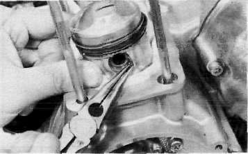
a. Install the connecting rods onto the crankshaft with the proper connecting rod bearings and apply molybedenum disulfide grease to the bolt threads. Apply torque evenly to both ends of the cap.
CAUTION:
While tightening, if a torque of 2.0 m-kg (14.5 ft-lb) or more is reached, DO NOT STOP tightening until final torque is reached.
If tightening is interrupted between 2.0 m-kg and 2.5 m-kg, loosen the nut to less than 2.0 m-kg and start again. Tighten to full torque specification without pausing.
Rod cap torque: 2.5 m-kg (18.0 ft-lb)
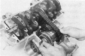
b. Install the proper crankshaft main bearings into the crankcase and place the crankshaft. Oil the bearings liberaly.
NOTE:
Do not forget to install the crankshaft oil seal (L.H.), blind plug (R.H.), "HY-VO" chain and cam chain on the crankshaft before installing. Also, install the chain guide into upper crankcase if removed.
c. Install the starter idle gear, shaft, stopper plate, and new lock plate. Tighten the bolt securely, and bend the lock tabs along the bolt flats.
Tightening torque: 1.0 m-kg (7.2 ft-lb)
d. Put the starter clutch and sprocket assembly in the "HY-VO" chain and lay it into the crankcase.
e. Install the A.C.G. Generator shaft into the starter clutch assembly.
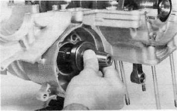
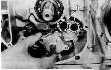
f. Install the "HY-VO" chain oil spray nozzle. Do not forget to install the new "O-ring" onto the nozzle.
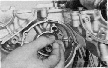
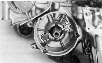
g. Install the new "O-ring" onto the bearing housing and install it with the panhead screw.
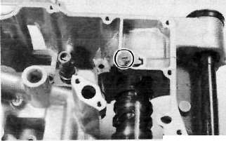
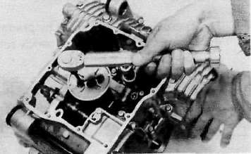
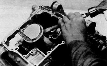
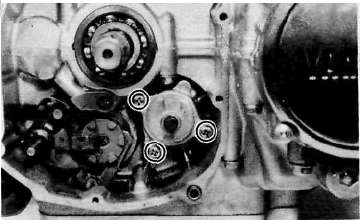
2. Lower crankcase a. Install the shift cam and secure it with the guide pin. Install the stopper plate and bolt and tighten securely.
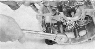
b. Install the neutral switch.
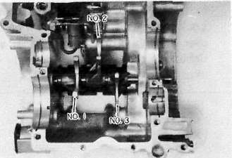
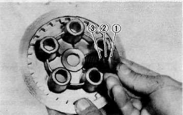
c. Install the shift forks and guide bar. Each shift fork is identified by a number cast on its side. All the numbers should face the left side and numbered 1, 2 and 3 from left.
d. Install the shift bar stopper securing screw and bolt.
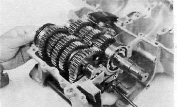
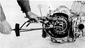
e. Install the transmission assembly into the crankcase, Next, install the HY-VO chain tensioner and chain guide.
CAUTION:
When installing the crankcase, make sure the HY-VO chain tensioner is set in place with its plunger in the proper position; otherwise, a dislodged plunger will result in damage to various part after crankcase installation.
Crankcase Assembly
Crankcase AssemblyCrankcase assembly
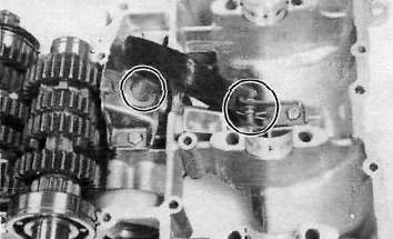
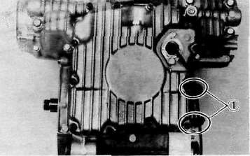
a. Apply Yamaha bond # 4 sealant or equivalent to the crankcase mating surface. Be very careful not to allow any sealant to come in contact with the oil gallerly "O-ring" and crankshaft bearings. It is extremely important, however, that sealant be applied around the case stud holes. Apply sealant to within 2~3 mm (0.08 - 0.12 in) of the bearings.
CAUTION:
Failure to apply sealant here will result in reduced oil pressure and possible crank seizure.
1. 2-~ 3 mm (0.08 — 0.12 in) Do not apply sealant.
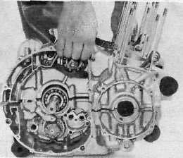
b. The crankcases are assembled by placing the upper case half on the bench and lowering the lower case onto it.
NOTE:
Be sure that shift fork No. 2 engages the groove in the 2nd pinion gear on the main axle.
CAUTION:
Before installing and torquing the crankcase bolts, check to make sure the transmission is functioning properly by shifting it by hand with the shift cam.
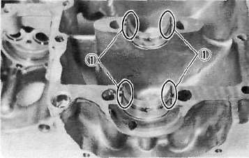
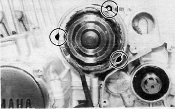
c. Start installation of the crankcase bolts with the center crankshaft area bolts. Place the two bolts without washers in the oil filter area.
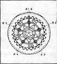
d. The crankcase bolts should be torqued in proper sequence. Refer to the tightening sequence in the illustration.
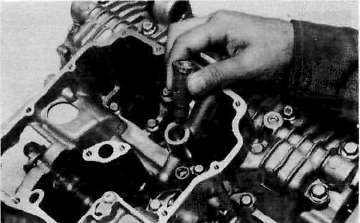
e. Install the right-front crankcase cover. 4. Oil pump and strainer cover a. Install the relief valve, strainer housing and strainer screen.
Tightening torque: 1.0m-kg(7.2ft-lb)
b. Install the strainer cover and torque the bolts to the specification.
Tightening torque: 1.0m-kg(7.2ft-lb)
1. Wire clamps
c. Install the shift lever assembly with the positioning spring is properly located on the stopper pin.
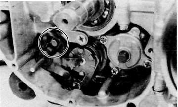
d. Install the oil pump assembly and oil pump securing screws.
e. Install the oil pump driven sprocket.
Pistons and Cylinders
Pistons and Cylindersa. Install the pistons on the rods. The arrow on the piston must point to the front of the engine.
NOTE:
Before installing the piston pin clips, cover the crankcase with a clean rag so you will not accidentally drop the circlip into the crankcase. Always install new piston pin circlips.
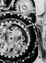
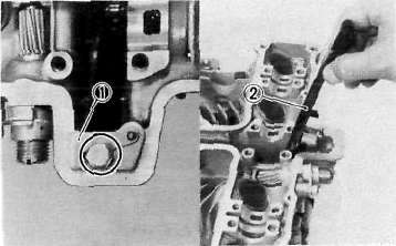
b. Install the rear chain guide on its pivot. Tighten the holding bolt until it stops and then loosen 1/4 turn and then tighten the lock nut.
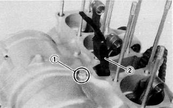
1. Holding bolt 2. Rear chain guide
c. Install the new cylinder base gasket and dowel pins. Install the new "O-rings" to the right side dowel pins.
d. Set the crankshaft so that the all pistons are equal height and align the piston rings as shown.
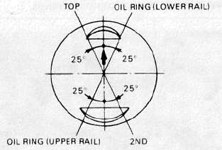
CAUTION;
Make sure the ends of the oil ring expanders are not overlapped.
NOTE:
Manufacturer's marks or numbers stamped on the rings are on the top side of the rings. Coat the pistons and rings well with oil.
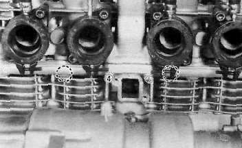
e. Install the piston ring compressors (special tool) and piston bases (special tool). Four piston bases are required.
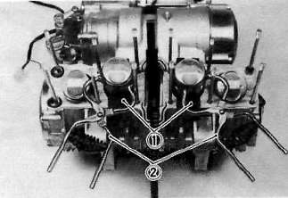
1. Piston bases 2. Piston ring compressors
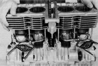
f. Tie the cam chain with a piece of mechanic's wire and feed it through the chain opening. Carefully lower the cylinder onto the pistons. Remove the ring compressors and piston bases and repeat this procedure for pistons 1 and 4.
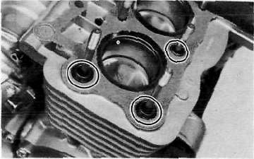
g. Install the cylinder securing nut (front side) and tighten it to the specification.
Tightening torque: 2.0 m-kg (14.5 ft-lb)
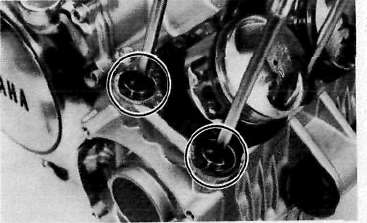
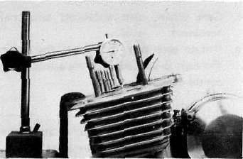
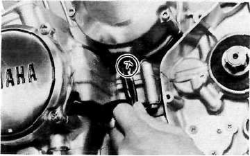
h. Set the dial guage on the No. 1 piston head center as shown to find the No. 1 piston top dead center and check whether the "T" mark on the timing plate and stationary pointer are aligned or not, If not, loosen the pointer securing screw and adjust.
AC Generator, Starter Motor and Pickup coil
AC Generator, Starter Motor and Pickup coilGenerator
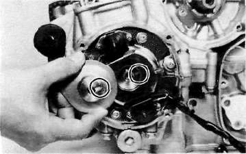
a. Install the rotor onto the shaft and tighten the bolt using the rotor holding tool (special tool) as shown.
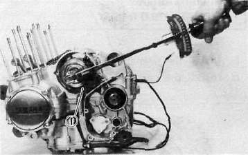
1. Rotor holding tool
Tightening torque: 3.5 m-kg (25.5 ft-lb)
b. Install the stator coil assembly onto the crankcase and align the grooves on the stator core with the bolt holes on the crankcase.
c. Install the A.C.G. cover assembly and tighten the bolts to the specification. Do not forget to install the new gasket.
Tightening torque: 1.0m-kg(7.2ft-lb)
Starter motor
a. Route the A.C.G. lead wires as shown.
b. Install the starter motor and tighten the bolts to the specification.
Tightening torque: 1.0m-kg (7.2fMb)
NOTE:
Be careful the "O-ring" is not damaged when installing the starter motor.
Pick-up coil assembly
a. Install the pick-up coil assembly onto the crankcase.
b. Install the timing plate on the crankshaft and tighten the bolt to the specification.
NOTE:
Note that there is the locating pin on the crankshaft and the corresponding slot in the timing plate which must be aligned to install the timing plate.
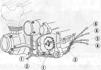
1. Clamp
2. To side stand switch
3. Band
4. Side stand switch lead wire
5. Pick up coil and lead wire
6. A.C Generator lead wire
Clutch
ClutchClutch assembly
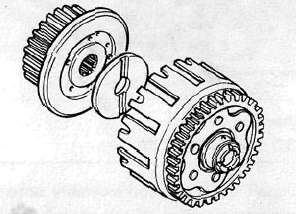
a. Install the primary drive gear and collar.
Tightening torque: 5.0 m-kg (36.0 ft-lb)
b- Install the primary driven gear assembly.
c. Install the clutch boss and thrust plate.
d. Install a new lock washer and nut and tighten the nut to the specified torque. Use the clutch boss holder (special tool).
Tightening torque: 7.0 m-kg (50.5 ft-lb)
1. Clutch boss holder
e. Bend the lock washer tabs along the nut flats.
f. Install the clutch plates and friction plates alternately on the clutch boss, starting with a friction plate and ending with a friction plate.
1. Third friction plate 2. Clutch boss spring
g. Install the plate washer, thrust bearing, and clutch pull rod into the clutch pressure plate from inside.
1. Pull rod 2. Thrust bearing 3. Plate washer
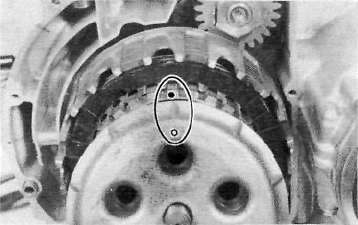
h. Install the pressure plate assembly onto the clutch boss.
NOTE:
Pressure plate has a dot on it which must line up with the dot on clutch boss.
i. Install the clutch springs and screws. Tighten the screws.
Clutch screw torque: 0.8m-kg(5.8ft-lb)
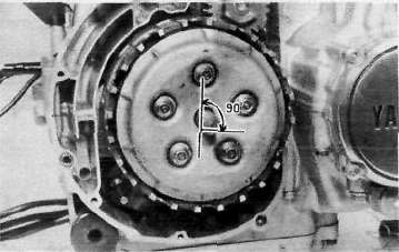
j. Set the gear of the clutch pull rod on the pressure plate facing approximately 90° from horizontal toward the rear; set the clutch lever (if installed) on the right crankcase cover parallel to the gasket surface and install the cover to the crankcase. Do not forget to install two dowel pins.
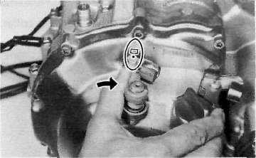
k. If the clutch lever has been removed, install the lever return spring and lever on the shaft after installing the right crankcase cover. In this case make sure that the punch mark on the lever should align with the mark on the crankcase cover when pushing the lever towards the front by hand and then install the circlip.
Cylinder head and Camshafts
Cylinder head and Camshaftsa. Install the new cylinder head gasket. Install the dowel pins and "o-rings".
b. Install the cylinder head onto the cylinder. Pull the cam chain through the cylinder head as it is installed. Tie the cam chain so that it does not fall into the crankcase.
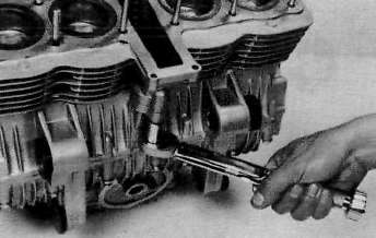
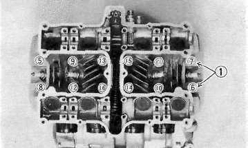
c. Place the upper cylinder head nuts and washers in place. Follow the illustration for the proper tightening sequence. Torque all nuts in two stages and final torque the upper nuts to the specification.
Tightening torque: 2.0 m-kg (14.5 ft-lb)
Don't forget the lower nuts on the front and rear of the cylinder head. Torque to the specification.
Tightening torque: 1.0 m-kg (7.2 ft-lb)
1. Copper washers
NOTE
Tighten the nuts in two stages, 1/2 torque value and then full torque value. Also lubricate the bolt threads with the engine oil to achieve proper torque values.
d. Install the front cam chain guide being certain that it is in its holder down below.
1. Lock washer 2. Front cam chain guide
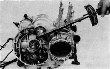
e. Rotate the engine in a counterclockwise direction until the crankcase pointer and "T" mark on the timing plate are aligned.
f. With the cylinder No. 1 and 4 at the top dead center, slip the cam chain over the sprocket.
g. Lubricate at! cam caps and cam bearings surfaces liberally with oil.
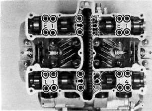
h. Place the cam caps in their proper positions. The caps are identified "1-1" through "I-4" for intake and "E-1" through "E-4" for exhaust. Install the bolts only finger tight.
CAUTION:
The cam caps must be tightened evenly or damage to the cylinder head, cam caps and cam will result. The spaces between the caps and cylinder head should be equal.
i. Torque the cam cap bolts in two stages and final torque to specification.
Tightening torque: 1.0 m-kg (7.2 ft-lb)
Cam chain, cam sprockets and chain tensioner.
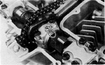
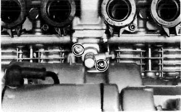
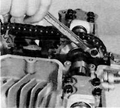
Cam chain, cam sprockets and chain tensioner.a. Rotate each cam shaft until the dot on the cam is aligned with the arrow on the center cam cap.
CAUTION:
Use extreme caution when rotating the cams. Two possible dangers exist. First, the wrench may contact the head and fracture it. Or second, a valve may become bent if the cam is turned the wrong way.
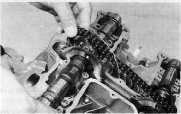
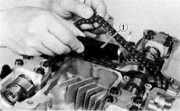
b. Carefully lift the cam chain from the exhaust cam sprocket and pull upward to remove any slack in the chain between the crankshaft and the exhaust cam sprocket. With all slack removed, place the chain back on the cam sprocket.
c. Grip each sprocket simultaneously and place them on the camshaft shoulders while continuing to keep tension on the chain from the crankshaft to the exhaust sprocket.
CAUTION:
Use only the special hardened shouldered bolts to install the cam chain sprockets to the cams.
Make sure the rollers of the cam chain are centered on both chain guides.
d. Rotate the sprockets slightly to align the bolt holes and insert one special bolt in each sprocket.
NOTE:
Tighten only finger tight at this time.
e. Install the center chain guide.
1. Cam chain guide
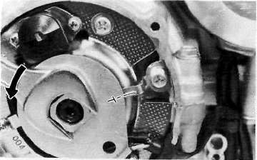
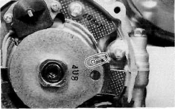
f. Rotate the crankshaft counterclockwise and align the "C" mark on the timing plate with the timing pointer.
g. Compress the cam chain tensioner and lock in the retracted position.
h. Install the chain tensioner to the engine and torque the bolts to the specification.
Tightening torque: 1.0 m-kg (7.2 ft-lb)
L Release the tensioner holding bolt, an audible click will be heard when the tensioner is released.
j. Torque the holding bolt and the lock nut to the specifications.
Holding bolt torque: 0.6 m-kg (4.3 ft-lb)
Lock nut torque: 0.9 m-kg (6.5 ft-lb)
k. Rotate the crankshaft more than one full revolution and align the "T" mark on the timing plate with the timing pointer. With the crankshaft at the "T" mark, the dots on the cams should be aligned with the raised arrows on the center cam caps. If they are not aligned, disassemble the sprockets and chain tensioner and repeat above procedures.
I. Rotate the crankshaft and install the two remaining shoulder bolts into the cam sprockets. Torque all four sprocket holding bolts to the specification.
CAUTION:
Be sure to attain the specified torque value to avoid the possibility of these bolts coming loose and causing serious damage to the engine.
Tightening torque: 2.0 m-kg (14.5 ft-lb)
m. Adjust all valves as described in the "PERIODIC INSPECTIONS AND ADJUSTMENTS".
n. Install the cylinder head cover with a new gasket.
o. Install the left crankcase covers. The left crankcase cover (pick-up coil cover) is required a gasket.