Chassis Maintenance
Chassis MaintenanceBrakes
BrakesFront brake adjustment
The brake can be adjusted by simply adjusting the free play of the brake lever. The piston in the caliper moves forward as the brake pad wears out, automatically adjusting the clearance between the brake pads and brake disc.
CAUTION: Proper lever free play is essential to avoid excessive brake drag.
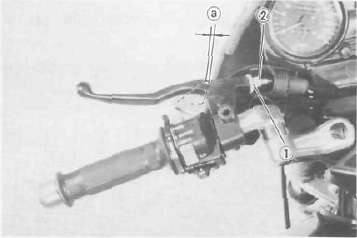
The free play at the end of the front brake lever should be 5 — 8 mm (0.2 — 0.3 in).
1. Loosen the lock nut.
2. Turn the adjuster so that the brake lever movement at the lever end is 5 - 8 mm (0.2 - 0.3 in) before the adjuster contacts the master cylinder piston.
3. After adjusting, tighten the lock nut
WARNING: Check the brake lever free play. Be sure the brake is working properly.
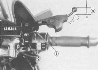
1 Adjuster 2. Lock nut a. 5 — 8 mm (0.2 — 0.3 in)
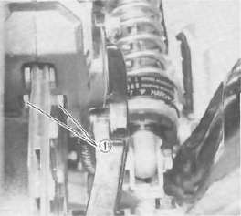
Rear brake pedal position adjustment
The brake pedal top end should be 27 - 33 mm (1.1 - 1.3 in) below the top of the footrest.
1. Remove the brake pedal pinch bolt and remove the brake pedal.
2. The punched mark on the brake pedal shaft and the punched mark on the brake pedal which must be aligned to install the brake pedal.
3. Install the brake pedal pinch bolt securely.
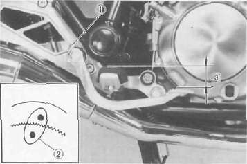
1. Pinch bolt 2 Punched marks a. 27 — 33 mm (1.1 —1.3 in)
Rear brake adjustment
The brake pedal free play is set at the factory. This free play ranges from where the brake pedal is trod to where the brake begins to take effect. No adjustment is necessary.
Free play: 20 - 30 mm (0.8 — 1.2 in)
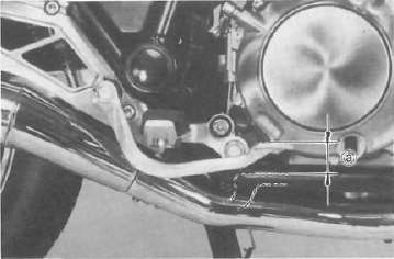
a. 20 - 30 mm {0.8 -1.2 in)
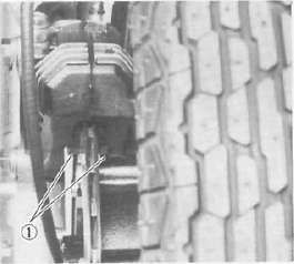
Front and rear brake pad check
A wear indicator is attached to each brake pad to facilitate disc brake pad checks. This indicator permits a visual check without disassembling the pads. To check, look at the pad wear indicator in back of the caliper. If any pad is worn to the wear limit, replace both pads in the caliper.
FRONT
1. Wear indicator
REAR
1 Wear indicator
Inspecting the brake fluid level
Insufficient brake fluid may allow air to enter the brake system, possibly causing the brake to become ineffective. Check the brake fluid level and replenish when necessary observing these precautions:
FRONT
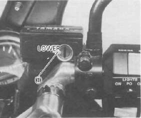
1. Lower level
REAR
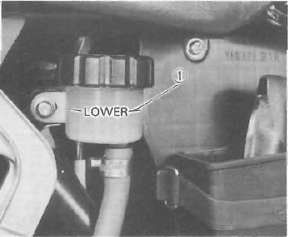
1. Lower level
1. Use only the designated quality brake fluid; otherwise, the rubber seals may deteriorate, causing leakage and poor brake performance.
Recommended brake fluid: DOT #3
2. Refill with the same type and brand of brake fluid; mixing fluids may result in a harmful chemical reaction and lead to poor performance.
3. Be careful that water or other contamination does not enter the master cylinder when refilling. Water will significantly lower the boiling point and may result in vapor lock.
4. Brake fluid may erode painted surfaces or plastic parts. Always clean up spilled fluid immediately.
Brake fluid replacement
1. Complete fluid replacement should be done whenever the caliper cylinder or master cylinder is disassembled, or the fluid becomes seriously contaminated.
2. Replace the following components whenever damaged or leaking.
a. Replace all brake seals every two years.
b. Replace all brake hoses every four years.
c. Replace the plunger kits every two years.
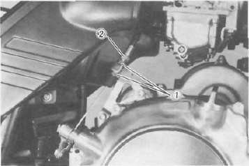
Brake light switch adjustment
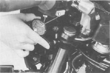
The brake light switch is operated by movement of the brake pedal. To adjust, hold the main body of the switch with your hand so it does not rotate and turn the adjusting nut. Proper adjustment is achieved when the brake light comes on just before the brake begins to take effect.
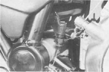
1. Main body 2. Adjusting nut
Clutch and Handlebars adjustment
Clutch and Handlebars adjustmentClutch adjustment
This model has two clutch cable length adjusters. The cable length adjusters are used to take up slack from cable stretch and to provide sufficient free play for proper clutch operation. Normally, once the clutch cable length adjuster (crankcase) is properly set; the only adjustment required is maintenance of free play at the clutch cable length adjuster (handlebar lever).
1. Loosen either the handlebar lever adjuster lock nut or the cable length adjuster lock nut.
2. Turn the cable length adjuster either in or out until proper lever free play is achieved.
Clutch lever free play: 2 —3 mm (0.08 —0.12 in)
1. Lock nut 2. Adjuster
1. Lock nut 2. Adjuster a. 2 - 3 mm (008 — 0.12 in)
Handlebars adjustment
1. Vertical adjustment
Five-stage adjustment is possible. a. Remove the cap and loosen the grip bar installation bolt.
1. Grip bar bolt
b. Loosen the grip bar and turn and align the adjusting collar either clockwise or counterclockwise. To adjust turn the collar counterclockwise to raise the grip ban turn the collar clockwise to lower the gip bar. (The red mark indicates the standard position.)
NOTE: Check to see that the projection on the handlebar fits a notch in the collar.
2. Horizontal adjustment
Four-stage adjustment is possible. a. Remove the cap and loosen the handlebar installation bolt.
1. Handlebar bolt
b. Loosen the handlebar and turn and align the adjusting collar either clockwise or counterclockwise. To adjust, turn the collar counterclockwise to move the handlebar inward, turn the collar clockwise to move the handlebar outward. (The red make indicates the standard position.)
NOTE: Check to see that the projection on the handlebar fits a notch in the collar.
Electrical
ElectricalELECTRICAL
Battery
1. The fluid level should be between the upper and lower level marks. Use only distillod water if refilling is necessary.
CAUTION: Normal tap water contains minerals which are harmful to a battery; therefore, refill only with distilled water.
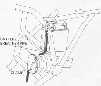
2. Always make sure the connections are correct when installing the battery. Make sure the breather pipe is properly connected, properly routed, and is not damaged or obstructed.
CAUTION: The battery must be charged before using to insure maximum performance. Failure to properly charge the battery before first use, or low electrolyte level will cause premature failure of the battery. Charging current: 1.4 amps/10 hrs or until the specific gravity reaches 1.280 at 20°C (68°F)
WARNING: Battery electrolyte is poisonous and dangerous, causing severe burns, etc. It contains sulfuric acid. Avoid contact with skin, eyes or clothing.
Antidote: EXTERNAL-Flush with water. INTERNAL-Drink large quantities of water or milk. Follow with milk of magnesia, beaten egg, or vegetable oil. Call physician immediately.
Eyes: Flush with water for 15 minutes and get prompt medical attention. Batteries produce explosive gasive gases. Keep sparks, flame, cigarettes, etc. away. Ventilate when charging or using in closed space. Always shield eyes when working near batteries. KEEP OUT OF REACH OF CHILDREN.
Spark plug
1. Check the electrode condition and wear, insulator color and electrode gap.
2. Use a wire gauge for measuring the plug gap.
3. If the electrodes become too worn, replace the spark plug.
4. When installing the plug, always clean the gasket surface. Wipe off any grime that might be present on the surface of the spark plug, and torque the spark plug properly.
Standard spark plug:
BPR8ES (NGK) Spark plug gap:
0.7 - 0.8 mm (0.028 ~ 0.032 in) Spark plug tightening torque:
20 Nm (2.0 mkg, 14 fMb)
Replacing the headlight bulb
This motorcycle is equipped with a quartz bulb headlight. If the headlight bulb burns out, replace the bulb as follows: 1. Remove the 2 screws holding the light unit assembly to the headlight body.
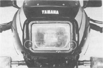
2. Disconnect the leads, and remove the light unit assembly.
3. Turn the bulb holder couterclockwise and remove the defective bulb.
WARNING: Keep flammable products or your hands away from the bulb while it is on, it will be hot. Do not touch the bulb until it cools down.
4. Slip a new bulb into position and secure it in place with the bulb holder.
CAUTION: Avoid touching the glass part of the bulb. Keep it free from oil; otherwise, the transparency of the glass, life of the bulb, and illuminous flux will be adversely affected. If oil gets on the bulb, throughly clean it with a cloth moistened with alcohol or lacquer thinner.
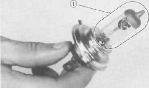
1. Don't touch
5. Reinstall the light unit assembly to the headlight body. Adjust the headlight beam if necessary.
Headlight beam adjustment
1. Horizontal adjustment:
To adjust the beam to the left, turn the adjusting screw clockwise. To adjust the beam to the right turn the screw counterclockwise.
2. Vertical adjustment:
To raise the beam, turn the adjusting screw clockwise.
To lower the beam, turn the screw counterclockwise.
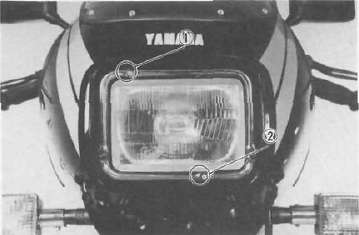
1. Horizontal adjusting screw 2. Vertical adjusting screw
Fuse replacement
1. The fuse block is located under the seat.
2. If any fuse is blown, turn off the ignition switch and the switch in the circuit in question, install a new fuse of proper amperage.
Turn on the switches, and see if the electrical device operates. If the fuse immediately blows again, find the cause in the circuit in question.
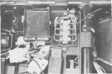
1. Main fuse 2. Spare fuse
WARNING: Do not use fuses of a higher amperage rating than those recommended. Substitution of a fuse of improper rating can cause extensive electrical system damage and possible fire.
Generator brushes replacement
The generator carbon brushes require periodical replacement.
1. Remove the generator cover screws and the left side generator cover.
2. Remove the screws and separate the brushes assembly from the cover.
3. Remove the panhead screws and replace the old brushes to new ones.
Fuel Petcock
Fuel PetcockFuel petcock cleaning
1. Turn the fuel petcock lever to the "RES". Remove the fuel pipe from the fuel petcock.
2. Remove the seat, the fuel tank clamp, and the fuel-tank-retainer plate.
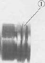
3. Lift the tank and remove the drain cover and clean it with solvent. If gasket is damaged, replace.
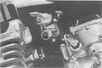
1. Drain cover
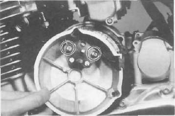
Fuel petcock disassembly
If the fuel petcock is leaking or excessively contaminated, it should be removed from the fuel tank and inspected.
1. Remove the fuel tank and position it so that fuel will not spill when the cock is removed.
2. Remove the petcock and inspect the filter screen. Replace the filter if seriously contaminated.
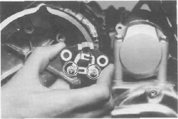
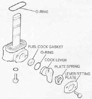
3. Remove the screws on front and rear of the petcock and remove the plate, gaskets, lever, and diaphragm.
4. Inspect all components and replace any that are damaged. If the diaphragm is in any way damaged, or the petcock body gasket surfaces scratched or corroded, the petcock assembly must be replaced. If there is abrasive damage to any component, the fuel tank must be drained and flushed.
5. Reassemble the petcock and install it on the fuel tank.
Other Lubrication points
Other Lubrication pointsCable inspection and lubrication
WARNING: Damage to the outer housing of the various cables, may cause corrosion and often free movement will be obstructed. An unsafe condition may result so replace such cables as soon as possible.
Lubricate the inner cable and cable end. If they do not operate smoothly, replace them.
Recommended lubricant: SAE 10W30 motor oil
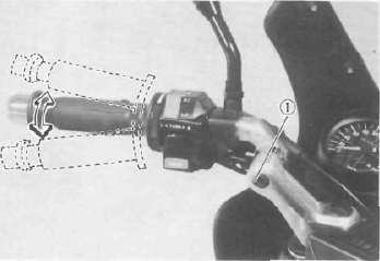
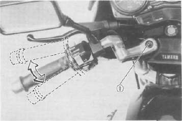
Throttle cable and grip lubrication
The throttle twist grip assembly should be greased when the cable is lubricated, since the grip must be removed to get at the end of the throttle cable. Two screws clamp the throttle housing to the handlebar. Once these two are removed, the end of the cable can be held high to pour in several drops of lubricant. With the throttle grip disassembled, coat the metal surface of the grip assembly with a suitable all-purpose grease to cut down friction.
Rear arm pivot bearings
The swing arm must pivot freely on its bearings but not have any excess play. Check and adjust pivot bearings if necessary. (Refer to CHAPTER 5. SWING ARM).
Brake and change pedals/brake and clutch levers
Lubricate the pivoting parts of each lever and pedal.
Recommended lubricants: SAE 10W30 motor oil
Center and side stand pivots
Lubricate the center and side stands at their pivot points.
Recommended lubricants: SAE 10W30 motor oil
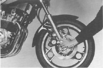
Steering Head Bearings
Steering Head BearingsSteering head adjustment
1. Raise the front end of the motorcycle so that there is no weight on the front wheel.
WARNING: Securely support the motorcycle so there is no danger of it falling over.
2. Grasp the bottom of the forks and gently rock the fork assembly backward and forward, checking for looseness in the steering assembly bearings.
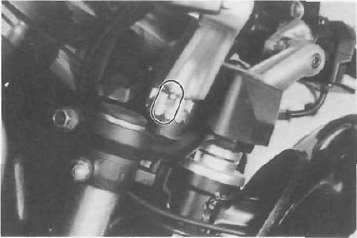
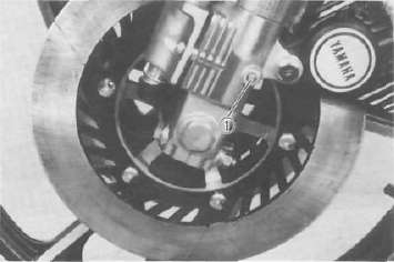
3. If there is looseness in the steering head, loosen the steering fitting bolt
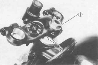
1. Steering fitting bolt 2. Steering fitting nut
4. Use steering nut wrench to loosen top steering fitting nut. The top nut serves as a lock nut.
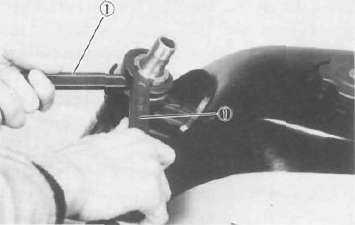
1. Steering nut wrench
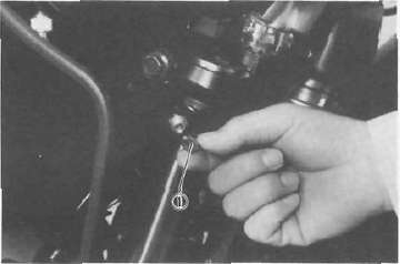
5. Tighten the lower steering fitting nut until the steering head is tight but does not bind when forks are turned.
6. Retighten the top steering fitting nut and steering fitting bolt.
7. Recheck steering adjustment to make sure there is no binding when the forks are moved from lock to lock. If necessary, repeat adjustment procedure.
Suspension
SuspensionFront fork oil change
WARNING.
1. Fork oil leakage can cause loss of stability and safe handling. Have any problem corrected before operating the motorcycle.
2. Securely support the motorcycle so there is no danger of it falling over.
1. Elevate the front wheel by placing a suitable stand under the engine.
2. Remove the rubber cap from the top of each fork.
3. Remove the air valve cap from the left fork.
4. Keep the valve open by pressing it for several seconds so that the air can be let out of the inner tube.
1. Air valve cap
5. Loosen the front fork pinch bolts and remove the cap bolts from the inner fork tubes.
1. Pinch bolt 2. Cap bolt
6. Place an open container under each drain hole. Remove the drain screw from each outer tube.
WARNING:
Do not let oil contact the disc brake components. If any oil should contact the brake components, it must be removed before the motorcycle is operated. Oil will cause diminished braking capacity and will damage the rubber components of the brake assembly.
1. Drain screw
7. After most of the oil has drained, slowly pump the forks up and down to remove any remaining oil.
8. Inspect the drain screw gasket. Replace if damaged. Reinstall the drain screws.
9. Pour the specified amout of oil into each the fork inner tube.
Front fork oil capacity (each fork): 286 cm3 (10.1 Imp oz, 9.67 US oz)
Recommended oil: SAE 5W type SE motor oil or equivalent
10. After filling, slowly pump the forks up and down to distribute the oil.
11. Inspect the O-ring on the cap bolt. Replace if damaged.
1. O-ring
12. Reinstall the cap bolt and tighten the pinch bolt.
Tightening torque: Cap bolt: 23 Nm (2.3 mkg, 17 ft-lb) Pinch bolt: 23 Nm (2.3 mkg, 17 ft lb)
13. Fill the fork with air using an air pump or pressurized air supply. Refer to "Front fork and rear shock absorber adjustment" for proper air pressure adjusting.
Maximum air pressure: 118 kPa (1.2 kg/cm2, 17.1 psi) Do not exceed this amount.
Since the right and left front forks are connected by one air hose, there is only one valve where the air pressure is measured and adjusted.
Front fork and rear shock absorber adjustment
Front fork:
1. Elevate the front wheel by placing the motorcycle on the centerstand.
NOTE: When checking and adjusting the air pressure, there should be no weight on the front end of the motorcycle.
2. Remove the valve cap from left fork.
3. Using the air check gauge, check and adjust the air pressure.
If the air pressure is increased, the suspension becomes stiffer and if decreased, it becomes softer.
1. Air gauge
To increase: Use an air pump or pressurized air supply To decrease: Release the air by pushing the valve.
NOTE:
An optional air check gauge is available. Please ask a nearby Yamaha dealer. P/No. 2X4-2811A-00.
Air pressure:
39.2 kPa (0.4 kg/cm2, 5.7 psi) Maximum air pressure:
118 kPa (1.2 kg/cm2, 17.1 psi) Minimum air pressure: Zero
CAUTION: Never exceed the maximum pressure, or oil seal damage may occur.
4. Install the valve cap securely.
Rear shock absorber:
The rear shock absorber of this model features a spring seat, which is a combined spring preload and damping adjuster. Normal adjustment can be made by turning this spring seat; whereas damping adjustment only can be made by the damping adjuster.
CAUTION: Before adjustment, make sure of the following:
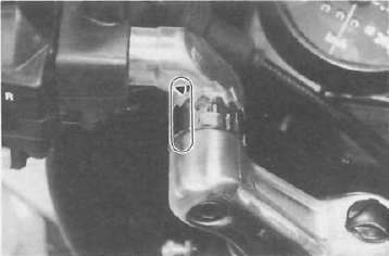
1. Turn in the damping adjuster fully. Then turn it back until its red painted slit aligns with the pointer "▼" on the spring cover.
2. For alignment in the absence of the red paint, turn the damping adjuster 6 clicks back from the fully turned-in position.
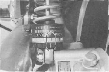
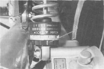
1. Spring seat adjustment
To increase the preload, turn the spring seat clockwise. To decrease the preload, turn the spring seat counterclockwise.
NOTE: When adjusting, use the special wrench which is included in the owner's tool kit
| Hard -------------------------------Soft | |
|
Mark |
|

1. Spring seat
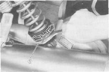
2. Damping adjustment
To increase the damping, turn the adjuster clockwise. To decrease the damping, turn the adjuster counterclockwise.
Standard position:
6 clicks turns out (or red mark) Minimum 12 clicks turns out Maximum 1 clicks turn out
NOTE: Make adjustment in less than one full turn of the adjuster.
1. Damping adjuster
Recommended combinations of the front fork and the rear shock absorber settings.
Use this table as guidance to meet specific riding and motorcycle load conditions.
|
Front frok |
Rear shock absorber |
Loading condition |
|||||
|
Air pressure |
Spring seat |
Damping adjuster turns out |
Solo rider |
With passenger |
With accessory equipment |
With accessory equipments and passenger |
|
|
1 |
39.2 ~ 78.5 kPa (0.4 ~ 0.8 kg/cm2, 5.7 - 11.4 psi) |
|
6 |
O |
|||
|
2 |
39.2 ~ 78.5 kPa (0.4 ~~ 0.8 kg/cm2, 5.7 ~11.4 psi) |
|
4 |
0 |
|||
|
3 |
58.8 - 98.1 kPa (0.6 ~ 1.0 kg/cm2. 8.5 — 14.2 psi) |
|
4 |
O |
|||
|
4 |
78.5 — 118 kPa (0.8 ~ 1.2 kg/cm2, 11.4- 17.1 psi) |
|
3 |
O |
|||


* Each numeral shows the damping value which can be set when the pointer is aligned with the individual slit in the spring seat. The damping adjuster may be further turned for a softer or a harder damping; in each of the above settings, it is recommended that the damping be adjusted by one (1) or two (2) clicks on the softer side and one (1) click on the harder side.
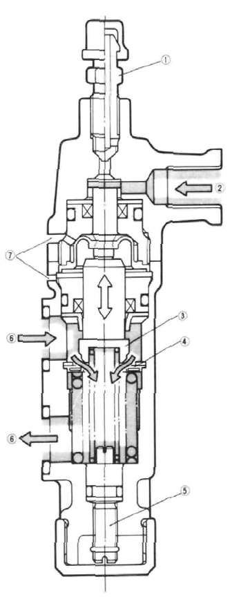
NOTE: Yamaha made a serious error in the original owner's manual regarding the anti-dive adjustment on the 900RK (essentially had it backwards). This is the corrected information, as per the September 1, 1983 TSB:
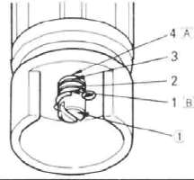
|
1 |
Air bleed screw |
|
2 |
Brake fluid |
|
3 |
Vaive |
|
4 |
Valve seat |
|
5 |
Adjusting bolt |
|
6 |
Fork oil |
|
7 |
Pilot hole |
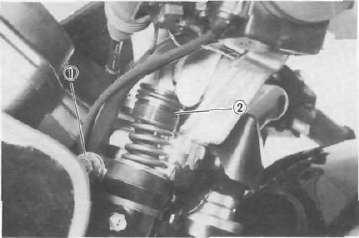
1. Remove the rubber cap from the bottom of the anti-dive unit.
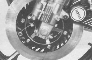
1. Rubber cap
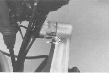
2. Look at the head of the adjusting bolt through the slots in the bottom of the anti-dive unit. In the standard position, two lines will be visible on the adjusting bolt head. Consult the fork adjustment chart below to determine the proper setting.
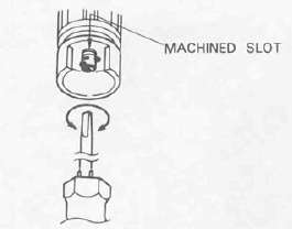
3. To decrease the anti-dive effect turn the adjusting bolt clockwise until the first line appears level to the top of the machined slot(s).
CAUTION: When the first line appears in the machined slot(s), the adjusting bolt will bottom in the anti-dive unit and a resistance will be felt. Do not attempt to turn the adjusting bolt beyond this point or the anti-dive unit will be damaged.
4. To increase the anti-dive effect, turn the adjusting bolt counterclockwise.
5. Replace the rubber cap.
WARNING: The anti-dive settings must be the same on both anti-dive units. Hence, be sure to perform the above procedure on both anti-dive units.
|
Adjusting bolt position |
Loading condition |
||
|
Solo rider |
With accessory equipments or passenger |
Wigh accessory equipments and passenger |
|
|
1 |
O |
||
|
2 |
O |
O |
|
|
3 |
O |
O |
|
|
4 |
O |
||