Chapter 7. Specifications
Chapter 7. SpecificationsGeneral Specifications
General SpecificationsI. GENERAL SPECIFICATIONS
| Model code number | 45T |
| Frame starting number | 45T-000101 |
| Engine starting number | 45T-000101 |
| Dimensions: | |
| Overall length | 2,190 mm (86.2 in) |
| Overall width | 735 mm (28.9 in} |
| Overall height | 1,245 mm (49.0 in) |
| Seat height | 790 mm (31.1 in) |
| Wheelbase | 1,480 mm (58.3 in) |
| Minimum ground clearance | 150 mm ( 5.9 in) |
| Weight: | |
| With oil and full fuel tank |
242 kg (534 lb) 2,900 mm (114.2 in) |
| Minimum turning radius | |
| Engine: | |
| Engine type | D.O.H.C, air-cooled, gasoline |
| Cylinder arrangement | Forward-incline, parallel 4-cylinder |
| Displacement | 749 cm3 (45.69 cu.in) |
| Bore x Stroke | 65.0 x 56.5 mm (2.559 x 2.224 in) |
| Compression ratio | 9.8: 1 |
| Compression pressure | 785- 1,177 kPa (8.0 -12.0 kg/cm2,.114- 171 psi) |
| Starting system | Electric |
| Lubrication system | Pressure lubricated, wet sump |
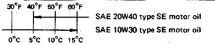
Engine oil type or grade
| Engine oil capacity: | |
| Periodic oil change | 2.5 L (2.2 Imp qt, 2.6 US qt) |
| Oil filter replacement | 2.8 L (2.5 Imp qt, 3.0 US qt) |
| Total amount | 3.6 L (3.2 Imp qt, 3.8 US qt) |
| Final gear oil: | |
| Grade or type | SAE 80 API "GL-4" Hypoid gear oil |
| Final gear case oil amount | 0.2 L (0.18 Imp qt, 0.21 US qt) |
| Air filter | Dry type element |
| Fuel: | |
| Type | Regular gasoline |
| Tank capacity | 22.0 L (4.84 Imp gal, 5.81 US gal) |
| Reserve amount | 5.0 L (1.10 Imp gal, 1.32 US gal) |
| Carburetor: | |
| Type | HSC33 x 4 |
| Manufacturer | HITACHI |
| Spark plug: | |
| Type | BPR8ES |
| Manufacturer | NGK |
| Gap | 0.7 - 0.8 mm (0.028 - 0.032 in) |
| Clutch type | Wet, multiple disc |
| Transmission: | |||
|
Primary reduction system |
Spur gear | ||
| Primary reduction ratio | 97/58(1.672) | ||
|
Secondary reduction system |
Shaft drive | ||
| Secondary reduction | |||
| Transmission output |
Type/teeth/ratio |
Spur gear, 48/37 (1.297) | |
| Middle gear case |
Type/teeth/ratio |
Bevel gear, 19/18(1.055) | |
| Final gear case |
Type/teeth/ratio |
Bevel gear, 32/11 (2.909) | |
| Transmission type | Constant mesh, 5-speed drum shifter | ||
| Operation | Left foot operation | ||
| Gear ratio: | 1st | 35/16 (2.187) | |
| 2nd | 30/20(1.500) | ||
| 3rd | 30/26 (1.153) | ||
| 4th | 28/30 (0.933) | ||
| 5th | 26/32 (0.812) | ||
| Chassis: | |||
| Frame type | Tubular steel double cradle | ||
| Caster angle | 27° | ||
| Trail | 114 mm (4.49 in) | ||
| Tire: | |||
| Tire type | Tubeless | ||
| Tire size (F) | 100/90 V 18 | ||
| Tire size (R) | 120/90 V 18 | ||
| Manufacturer | BRIDGESTONE, PIRELLI | ||
| Tire pressure: | (Cold pressure) | ||
|
Up to 90 kg (198 lb) load* |
(F) | 226 kPa (2.3 kg/cm2, 32 psi) | |
| (R) | 245 kPa (2.5 kg/cm2, 36 psi) | ||
|
90 kg (198 lb) Maximum load* |
(F) | 245 kPa (2.5 kg/cm2, 36 psi) | |
| (R) | 284 kPa (2.9 kg/cm2, 42 psi) | ||
| High-speed ringing | (F) | 245 kPa (2.5 kg/cm2, 36 psi) | |
| (R) | 284 kPa (2.9 kg/cm2, 42 psi) | ||
|
*Total weight of accessories, etc. |
excpeting | ||
| motorcycle | |||
| Brake: | |||
| Front brake type | Dual hydraulic disc | ||
| Operation | Right hand | ||
| Rear brake type | Single hydraulic disc | ||
| Operation | Right foot | ||
| Suspension: | |||
| Front suspension | Telescopic fork | ||
| Rear suspension | Swingarm | ||
| Shock absorber: | |||
| Front shock absorber | Oil damper, and coil spring | ||
| Rear shock absorber | Oil damper, and coil spring | ||
| Wheel travel: | |||
| Front wheel travel | 150 mm (5.9 in) | ||
| Rear wheel travel | 100 mm (3.9 in) | ||
| Electrical: | |||
| Ignition system | Battery ignition (Full transistor ignition) | ||
| Generator system | A.C. generator | ||
| Battery type or model | YB14L | ||
| Battery capacity | 12V 14AH | ||
|
Headlight type: |
Bulb type (HALOGEN) | ||
| Bulb wattage x Pcs: | |
| Headlight | 60W/55W x 1 |
| Flasher light | 27Wx4 |
| Tail/Brake light | 8W/27W x 2 |
| Meter light | 3.4W x 6 |
| Auxiliary light | 4Wx 1 |
| Indicator light wattage x Pcs: | |
| NEUTRAL | 3.4W x 1 |
| HIGH BEAM | 3.4W x 1 |
| TURN | 3.4W x 2 |
| OIL | 3.4W x 1 |
Engine Specifications
Engine SpecificationsA. ENGINE
Cylinder head:
Volume 24,5 ±0.4 cm3 (1.49 ± 0.0244 cu.in)
Warp limit < 0.03 mm (0.0012 in)
 * Lines indicate straightedge measurement
Cylinder:
Material Aluminum alloy with pressed-in sleeve
Bore size 65 mm (2.56 in)
Taper limit < 0.05 mm (0.0020 in) >
Out-of-round limit <0.01 mm (0.0004 in) >
Camshaft:
| Drive method |
Chain drive (Center) | |
| Cam cap inside diameter |
25+ 0.021-0 mm (0.984+008 -0in ) |
|
| Camshaft outside diameter |
25- 0.020-0.033 mm (0.984+008 -0.0013in )
|
|
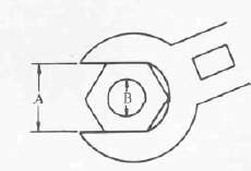
| Shaft-to-cap clearance Cam dimensions |
0.020 ~ 0.054 mm (0.0008 ~ 0.0021 in) |
|

| Intake | 'A" | 36.8 mm (1.449 in) |
| 'B" | 28.1 mm (1.106 in) | |
| •C" | 8.8 mm (0.346 in) | |
| Exhaust | 'A" | 36.3 mm (1.429 in) |
| 'B" | 28.06 mm (1.105 in) | |
| •C" | 8.3 mm (0.327 in) |
Valve timing
T.D.C.

IN. Open B.T.D.C. 38
IN. Close A.B.D.C. 58°
EX. Open B.B.D.C. 56°
EX. Close A.T.D.C. 36°
Overlap a = 74°

Maximum runout: 0.06 mm (0.0024 in)
| Cam chain type/Number of links | BUSH-CHAIN/120 |
| Cam chain adjustment method | Automatic |
|
Valve, Valve seat, Valve guide: |
||||
| Valve clearance (Cold) | IN. | 0.11 - | -0.15mm (0.0043- | - 0.0059 in) |
| EX. | 0.16- | - 0.20 mm (0.0063 - | - 0.0079 in) |
Valve dimensions
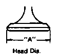
| "A" Head dia. | IN. | 34 ±0.1 mm (1.34 ± 0.004 in) |
| EX. | 28 ±0.1 mm (1.10 ± 0.004 in) |

| "B" Face width | IN. | 2.3 mm (0.091 in) |
| EX. | 2.3 mm (0.091 in) |
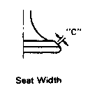
| "C" Seat limit width | IN. | 1 +0.1 mm (0.039 ± 0.004 in) |
| EX. | 1 ±0.1 mm (0.039 ± 0.004 in) |

| "D" Margin thickness limit | IN. | 1.2 + 0.2 mm (0.0472 ± 0.008 in) |
| EX. | 1.0 ± 0.2 mm (0.0394 ± 0.008 in) |
| Stem outside diameter | IN. | 7 -0010-0.025mm (0.2756-0.0004 -0.0010 in) |
| EX. | 7 -0025-0.040mm (0.2756-0.0010 -0.0016 in | |
| Guide inside diameter | IN. | 7+0.012 -0mm(0.2756 +0.0005 -0in) |
| EX. | 7+0.012 -0mm(0.2756 +0.0005 -0in) | |
| Stem-to-guide clearance | IN. | 0.010 ~ 0.037 mm (0.0004 ~ 0.0015 in) |
| EX. | 0.025 ~ 0.052 mm (0.0010 ~ 0.0020 in) | |
| Stem runout limit | < 0.03 mm (0.0012 in) > |

| Valve seat width standard | 0.9-1.1 mm (0.035 ~ 0.043 in) |
| < Limit > | < 2.0 mm (0.080 in) > |
| Valve spring: | |||
| Free length | |||
| Inner spring | IN. EX. | 35.9 mm (1.413 in) 35.9 mm (1.413 in) | |
| Outer spring | IN. EX. | 39.5 mm (1.555 in) 39.5 mm (1.555 in) | |
| Spring rate | |||
| Inner spring | IN. | K1 : 2.36 kg/mm (132 lb/in) | K2 : 1.84 kg/mm (103 lb/in) |
| EX. | K1 : 2.36 kg/mm (132 lb/in) | K2 : 1.84 kg/mm (103 lb/in) | |
| Outer spring | IN. | K1 : 4.58 kg/mm (256 lb/in) | K2 : 3.464 kg/mm (194 lb/in) |
| EX. | K1 : 4.58 kg/mm (256 lb/in) | K2 : 3.464 kg/mm (194 lb/in) | |
| Compression length (Valve closed) | |||
| Inner spring | IN. EX. | 31.0 mm (1.220 in) 31.0 mm (1.220 in) |
|
| Outer spring | IN. EX. | 34.0 mm (1.339 in) 34.0 mm (1.339 in) |
|
| Compression force (Valve closed) | |||
| Inner spring | IN. EX. | 8.1 ~9.9 kg (17.9-21.8 lb) 8.1 -9.9 kg (17.9-21.8 lb) |
|
| Outer spring | IN. EX. | 17.6-20.6 kg (38.8-45.4 lb) 17.6-20.6 kg (38.8-45.4 lb) |
|
Tilt limit |
||
| Inner spring | IN. & EX. | 2.5 /1.7 mm (0.067 in) |
| Outer spring | IN. & EX. | 2.5°/1.7mm (0.067 in) |
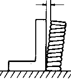
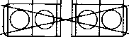
Direction of winding (Top view)
Intake

Exhaust

Piston:
Piston size/Measuring point (A)
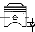
65.0 mm (2.559 in)/7.8 mm (0.307 in) (From bottom line of piston skirt)
| Clearance between piston & Cylinder | 0.03 ~ 0.05 mm (0.0012 ~ 0.0020 in) |
| Oversize 1 st | - |
| 2nd | 65.50 mm (2.579 in) |
| 3rd | — |
| 4th | 66.00 mm (2.598 in) |
| Piston pin hole off-set | 0.5 mm (0.02 in) inside |
Piston ring:
Sectional sketch
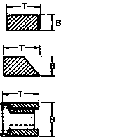
| Top ring |
D 1,-0.01mm/nn>n,-0.0004i > B 1-2 -0.03 mm <0-0472-0.0012 m) |
| T = 2.7 ± 0.1 mm (0.106 ± 0.004 in) | |
| 2nd ring | B=1.2:^mm(0.0472Z°Sin) |
| T = 2.7 + 0.1 mm (0.106 ± 0.004 in) | |
| Oil ring | B = 2.5 mm (0.098 in) |
| T = 2.8 ± 0.15 mm (0.110 ± 0.0059 in) |
| End gap (Installed) | Top ring | 0.15 ~ 0.35 mm (0.0059 ~ 0.0138 in) |
| Limit | < 1.0 mm (0.039 in) > | |
| 2nd ring | 0.15 ~ 0.35 mm (0.0059 ~ 0.0138 in) < 1.0 mm (0.039 in) > | |
| Oil ring | 0.3 ~ 0.9 mm (0.012 ~ 0.035 in) < 1.5 mm (0.059 in) > | |
| Side clearance | ||
| Limit | Top ring | 0.03 ~ 0.07 mm (0.0012 ~ 0.0028 in) < 0.15 mm (0.0059 in) > |
| 2nd ring | 0.02 ~ 0.06 mm (0.0008 ~ 0.0024 in) < 0.15 mm (0.0059 in) > |
| Plating or coating |
Top ring |
Chrome plated, Ferox coating |
| 2nd ring | Chrome plated, Ferox coating | |
| Oil ring | Chrome plated, Ferox coating |
|
Connecting rod: |
|
| Oil clearance | 0.016 ~ 0.040 mm (0.0006 ~ 0.0016 in) |
| Color code | 1. Blue, 2. Black, 3. Brown, 4. Green |
Crankshaft:

| Assembly width "B" | 341.4 ± 0.6 mm (13.44 ± 0.024 in) |
| Deflection limit "C" | < 0.03 mm (0.0012 in) > |
| Big end side clearance "D" | 0.16 ~ 0.26 mm (0.0063 ~ 0.00102 in) |
| Journal oil clearance | 0.020 ~ 0.044 mm (0.0008 ~ 0.0017 in) |
| Color code — corresponding size | Blue | 1.5 +0.008 +0.002 mm (0.0591 +0.00024 +0.00008 |
| Black | 1.5 +0.002 -0.002 mm (0.0591 +0.00008 -0.00008 | |
| Brown | 1.5 -0.002 -0.006 mm (0.0591 -0.0008 -0.00024 | |
| Green | 1.5 -0.006 -0.010 mm (0.0591 -0.00024 -0.00039 | |
| Yellow | 1.5 -0.010 -0.014 mm (0.0591 -0.00039 -0.00055 |
| Clutch: | |
| Friction plate thickness/Quantity | 3.0 ± 0.1 mm (0.12 ± 0.004 in)/8 |
| Wear limit | < 2.8 mm (0.11 in) > |
| Clutch plate thickness/Quantity | 2.0 ± 0.1 mm (0.080 ± 0.004 in)/7 |
| Warp limit | < 0.05 mm (0.002 in) > |
| Clutch spring free length/Quantity | 42.8 mm (1.685 in)/5 |
| Minimum length | 41.8 mm (1.622 in) |
| Primary reduction gear backlash tolerance | 120 |
| Primary drive gear | |
| Backlash numer | 87~93 |
| Primary driven gear | |
| Backlash numer | 25~31 |
| Clutch release method | Rack & Piston pull, Outer pull |
| Transmission: | |
| Main axle run-out limit |
< 0.08 mm (0.0031 in) > |
| Shifter: | |
| Shifter type | Guide bar |
|
Carburetor: |
||
|
Type/manufacturer/quantity |
HSC33-11/HITACHI/4 | |
|
I.D. mark |
41Y00 | |
|
Throttle Valve Size |
12.5° | |
| Main jet | (M.J.) | #106 |
| Main air jet | (M.A.J.) | #70 |
| Jet needle | UN.) | Y-18 |
| Pilot jet | (P.J.) | #40 |
| Pilot air jet | (P.A.J.) | #225 |
| Pilot screw (turns out) | (P.S.) | Pre-set |
| Pilot outlet size | (P.O.) | Φ 0.9 |
| Starter jet | (G.S.) | #43 |
| Valve seat size | (V.S.) | Φ 2.0 |
| Fuel level | (F.L.) | 1.0 ±1 mm (0.0394 ± 0.039 in) |
|
Engine idling speed |
1,100 ± 50 r/min | |
|
Vacuum pressure at idling speed |
180mmHg (7.09 inHg) | |
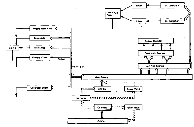
| Lubrication system: | |
| Oil filter type | Paper filter |
| Oil pump type | Trochoid pump |
| Tip clearance | 0.03 ~ 0.09 mm (0.0012 ~ 0.0035 in) |
| Side clearance | 0.03 ~ 0.08 mm (0.0012 ~ 0.0031 in) |
| Bypath valve setting pressure | 98 ± 20 kPa (1.0 ± 0.2 kg/cm2, 14.2 ± 2.8 psi) |
| Relief valve operating pressure | 490 + 50 kPa (5.0 ± 0.5 kg/cm2, 71.1 + 7.1 psi) |
| Lubrication diagram |

| Middle gear backlash | 0.1 - | ~ 0.2 mm (0.004 - | - 0,008 in) |
| Final gear backlash | 0.1 - | -0.2 mm (0.004- | - 0.008 in) |
Crankcase tightening sequence
LOWER CASE

UPPER CASE

Tightening Torque:
8 mm bolt: 24 Nm (2.4 m-kg, 17ft-lb) 6 mm bolt: 12 Nm (1.2 m-kg, 8.7 ft-lb)
|
Engine fastener Tightening Torque
|
||||||||
|
Part to be tightened |
Part name |
Thread size |
Q'ty |
Tightening torque |
Remarks |
|||
| Nm | mkg | ft lb | ||||||
|
ENGINE: |
||||||||
|
Camshaft cap |
Bolt | M6x1.0 | 24 |
10 1.0 7.2 |
Tighten in stages | |||
|
Cam chain (Front) (Rear) |
Stud bolt Nut
Stud bolt Nut |
M6x1.0 M6x1.0 M6x1.0 M6x1.0 |
2 2 2 2 |
5 0. 5 3.6 10 1.0 7.2 |
Apply oil Apply oil | |||
|
Exhaust pipe |
Stud bolt | M6x1.0 | 8 |
8 0.8 5.8 |
Apply oil | |||
|
Oil passage blind plug |
Screw | M6x1.0 | 1 |
7 0.7 5.1 |
||||
|
YICS passage |
Stud bolt Nut Blind plug |
M8x1.25 M8x1.25 M12x1.25 |
2
2 2 |
15 1.5 11 |
Apply oil | |||
|
Spark plug |
— | M14X1.25 | 4 |
20 2.0 14 |
||||
|
Cylinder head |
Nut | M10x1.25 | 12 |
32 3.2 23 |
Apply oil | |||
|
Cylinder head cover |
Bolt | M6x1.0 | 8 |
10 1.0 7.2 |
||||
|
Cam chain (Cylinder-Front) |
Stud bolt
Nut |
M8x1.25 M8x1.25 |
1
1 |
8 0.8 5.8 |
Apply oil | |||
|
Connecting rod |
Nut | M8x0.75 | 8 |
38 3.8 27 |
Apply Molybedenum disulfide grease |
|||
|
Cam sprocket |
Bolt | M7x1.0 | 4 |
20 2.0 14 |
||||
|
Cam chain tensioner |
Bolt | M6x1.0 | 2 |
10 1.0 7.2 |
||||
|
Cam chain tensioner guide |
Bolt | M8x1.25 | 1 |
3 0.3 2.2 |
||||
|
Oil Pump cover |
Screw | M6x1.0 | 4 |
7 0.7 5.1 |
||||
|
Strainer housing |
Screw | M6x1.0 | 3 |
7 0.7 5.1 |
||||
|
Oil pump |
Bolt | M6x1.0 | 3 |
12 1.2 8.7 |
||||
|
Oil filter |
Union bolt | M20x1.5 | 1 |
15 1.5 11 |
||||
|
Engine drain bolt |
Bolt | M14x1.5 | 1 |
43 4.3 31 |
||||
|
Strainer cover |
Bolt | M6x1.0 | 13 |
12 1.2 8.7 |
||||
|
Oil pump sprocket |
Bolt | M6x1.0 | 1 |
12 1.2 8.7 |
||||
|
Buffle plate |
Screw | M6x1.0 | 3 |
7 0.7 5.1 |
||||
|
Oil cooler adapter plate |
Union bolt | M20x1.5 | 1 |
50 5.0 36 |
||||
|
Part to be tightened |
Part name |
Thread size |
Q'ty |
Tightening torque |
Remarks |
||
| Nm | mkg | ft-lb | |||||
| Oil cooler hose and adapter | Bolt | M6x1.0 | 4 | 12 | 1.2 | 8.7 | |
| Oil hose | Bolt | M6x1.0 | 1 | 12 | 1.2 | 8.7 | |
| Oil cooler | Bolt | M6x1.0 | 3 | 10 | 1.0 | 7.2 | |
| Oil cooler hose clamp | Nut | M8x1.25 | 1 | 10 | 1.0 | 7.2 | |
| Carburetor joint | Bolt | M6x1.0 | 8 | 12 | 1.2 | 8.7 | |
| Air filter case cover | Screw | M6xt.O | 4 | 5 | 0.5 | 3.6 | |
| Air filter case and frame | Bolt | M6x1.0 | 3 | 5 | 0.5 | 3.6 | |
| Exhaust pipe joint band | Bolt | M8x1.25 | 6 | 20 | 2.0 | 14 | |
| Exhaust pipe ring nut | Nut | M6x1.0 | 8 | 10 | 1.0 | 7.2 | |
| Exhaust pipe and frame | Bolt | M1 0x1.25 | 2 | 25 | 2.5 | 18 | |
| Cylinder | Stud bolt Bolt | M10x1.25 M10X1.25 | 8
4 |
20 20 | 2.0 2.0 | 14
14 |
|
| Crankcase | Bolt Bolt | M8x1.25 M6x1-0 | 19
19 |
24
12 |
2.4 1.2 | 17 8.7 | |
| Bearing plate stopper | Screw | M8x1.25 | 4 | 25 | 2.5 | 18 | |
| Breaker cover | Screw | M6x1.0 | 8 | 8 | 0.8 | 5.8 | |
| Generator cover . | Bolt | M6x1.0 | 3 | 12 | 1.2 | 8.7 | |
| Generator housing bearing | Screw | M6x1.0 | 3 | 10 | 1.0 | 7.2 | |
| Change cover | Bolt | M6x1.0 | 10 | 12 | 1.2 | 8.7 | |
| Drive shaft housing bearing | Bolt | M6x1.0 | 3 | 12 | 1.2 | 8.7 | |
| Clutch cover | Bolt | M6x1.0 | 10 | 12 | 1.2 | 8.7 | |
| Clutch cable holder | Bolt | M6x1.0 | 2 | 12 | 1.2 | 8.7 | |
| Middle drain bolt | Bolt | M8x1.25 | 1 | 16 | 1.6 | 11 | |
| Breather pipe 1 | Screw | M6x1.0 | 3 | 7 | 0.7 | 5.1 | |
| Breather pipe 2 | Screw | M6x1.0 | 4 | 7 | 0.7 | 5.1 | |
| Main gallary blind plug | Plug | M20X1.5 | 2 | 12 | 1.2 | 8.7 | Apply oil |
| Stopper plate | Bolt | M6x1.0 | 1 | 10 | 1.0 | 7.2 | |
| Clutch starter outer | Bolt | M8x1.25 | 3 | 25 | 2.5 | 18 | |
| Upper guide | Bolt | M6x1.0 | 3 | 10 | 1.0 | 7.2 | |
| Clutch pressure plate | Bolt | M6x1.0 | 5 | 8 | 0.8 | 5.8 | |
| Clutch boss | Nut | M20X1.0 | 1 | 70 | 7.0 | 50 | |
| Drive shaft bearing | Nut | M34x1.0 | 1 | 110 | 11.0 | 80 | |
|
Part to be tightened |
Part name |
Thread size |
Q'ty |
Tightening torque |
Remarks |
||
| Nm | mkg | ft ib | |||||
| Driven shaft bearing | Nut | M65x1.5 | 1 | 110 | 11.0 | 80 | |
| Middle gear flange | Nut | M14x1.5 | 1 | 90 | 9.0 | 65 | |
| Housing bearing | Bolt | M8x1.25 | 4 | 25 | 2.5 | 18 | |
| Stopper plate | Screw Bolt | M6x1.0 M6x1.0 | 1
1 |
7 8 | 0.7 0.8 | 5.1 5.8 | |
| Change pedal | Bolt | M6x1.0 | 1 | 10 | 1.0 | 7.2 | |
| Change pedal link | Nut | M6x1.0 | 2 | 10 | 1.0 | 7.2 | |
| A.C. Generator | Bolt | M10x1.25 | 1 | 55 | 5.5 | 40 | |
| Pick-up coil base | Screw | M6x1.0 | 2 | 8 | 0.8 | 5.8 | |
| Rotor | Bolt | M8x1.25 | 1 | 24 | 2.4 | 17 | |
| Brush | Screw | M6x1.0 | 2 | 8 | 0.8 | 5.8 | |
| Timing plate | Screw | M6x1.0 | 1 | 8 | 0.8 | 5.8 | |
| Starter motor | Bolt | M6x1.0 | 2 | 7 | 0.7 | 5.1 | |
| Oil level switch | Bolt | M6x1.0 | 2 | 7 | 0.7 | 5.1 | |
| Drive shaft | U Nut | M14x1.5 | 1 | 110 | 11.0 | 80 | |
| Bearing cap | Bolt Nut | M10x1.25 M8x1.25 | 2
6 |
23 23 | 2.3 2.3 | 17
17 |
|
| Oil mount screw | Plug | M14x1.5 | 1 | 23 | 2.3 | 17 | |
| Oil drain screw | Plug | M14x1.5 | 1 | 23 | 2.3 | 17 | |
| Bearing retainer | — | M65x1.5 | 1 | 110 | 11.0 | 80 | |
| Final gear case | Stud bolt Stud bolt | M10x1.25 M8x1.25 | 4
6 |
17 9 | 1.7
0.9 |
12 6.5 | |
Chassis Specifications
Chassis SpecificationsCHASSIS
|
Steering system: |
||||
|
Steering bearing type |
Taper roller bearing KOYO 32005 KOYO 32006 | |||
|
Lock-to-lock angle |
35° | |||
|
Front suspension: |
||||
|
Front fork travel |
150 mm (5.91 in) | |||
|
Fork spring free length limit |
517.5 mm (20.4 in) | |||
|
Spring rate/Stroke |
K1 | 7.2 N/mm (0.72 kg/mm, 40.3 lb/in)/ 0-100 mm (0~3.94 in) | ||
| K2 | 10.4 N/mm (1.04 kg/mm, 58.2 lb/in)/ 100 ~ 150 mm (3.94 ~ 5.91 in) | |||
|
Optional spring |
No. | |||
|
Oil capacity |
286 ± 4 cm3 (10.1 + 0.14 Imp oz, 9.67 ± 0.14 US oz) | |||
|
Oil level |
168 mm (6.61 in)
(From top of inner tube fully compressed without spring) |
|||
|
Oil grade |
SAE 5W type SE motor oil or equivalent | |||
|
Rear suspension: |
||||
|
Shock absorber travel |
75 mm (2.95 in) | |||
|
Spring free length |
237 mm (9.33 in) | |||
|
Spring rate/Stroke |
K1 | 21.5 N/mm (2.15 kg/mm, 120.4 lb/in)/ 0~36 mm (0 ~ 1.42 in) | ||
| K2 | 30.0 N/mm (3.0 kg/mm, 168.0 lb/in)/ 36 ~75 mm (1.42 ~ 2.95 in) | |||
|
Optional spring |
No. | |||
|
Enclosed gas pressure |
150 kPa (15 kg/cm2, 213 psi) | |||
|
Rear arm: |
||||
|
Swingarm free play limit |
End | 1 mm (0.04 in) | ||
| Side | 1 mm (0.04 in) | |||
|
Wheel: |
||||
|
Front wheel type |
Cast wheel | |||
|
Rear wheel type |
Cast wheel | |||
|
Front rim size/Material |
MT2.15x 18/Aluminum | |||
|
Rear rim size/Material |
MT2.75x 18/Aluminum | |||
|
Rim runout limit |
Vertical | < 1.0 mm (0.04 in) > | ||
| Lateral | < 0.5 mm (0.02 in) > | |||
|
Disc brake: |
||||
|
Type |
Front | Dual disc | ||
| Rear | Single disc | |||
|
Outside dia. x Thickness |
Front | 267 x 7.5 mm (10.5 x 0.30 in) | ||
| Rear | 267 x 8.5 mm (10.5 x 0.33 in) | |||
|
Pad thickness |
Front | 5.5 mm (0.22 in) | ||
| Rear | 5.5 mm (0.22 in) | |||
|
Limit |
Front | < 0.5 mm (0.020 in) > | ||
| 1 | Rear | < 0.5 mm (0.020 in) > | ||

| Master cylinder inside dia. | Front | 15.87 mm (0.62 in) |
| Rear | 12.7 mm (0.50 in) | |
| Caliper cylinder inside dia. | F ront | 42.85 mm (1.69 in) |
| Rear | 42.85 mm (1.69 in) | |
| Brake fluid type | DOT #3 |
| Brake lever & Brake pedal: | |
| Brake lever free play | 5.0 ~ 8.0 mm (0.2 ~ 0.3 in) |
| Brake pedal free play | 20 ~ 30 mm (0.8 -1.2 in) |
| Brake pedal position | 30 mm (1.2 in) |
| (Vertical height below footrest top.) | |
| Clutch lever free play | 2~3mm (0.08 ~ 0.12 in) |
Recommended rear shock absorber settings.
Use this table as guidance to meet specific riding and motorcycle load conditions.
|
Rear shock absorber |
Loading condition |
||||
| Spring seat | Damping
adjuster turns out* |
Solo rider | With passenger | With accessory
equipment |
With accessory
equipment and passenger |
 |
6 |
O |
|||
 |
4 |
O |
|||
 |
4 |
O |
|||
 |
3 |
O |
|||
Each numeral shows the damping value which can be set when the pointer is aligned with the individual slit in the spring seat.
The damping adjuster may be further turned for a softer or harder damping; in each of the above settings, it is recommended that the damping be adjusted by one (1) or two (2) clicks on the softer side and one (1) click on the harder side.
Electrical Specifications
Electrical Specifications| Voltage | 12V |
| Ignition system: | |
| Ignition timing (B.T.D.C.) | 7°/1,050r/min |
| Advanced timing (B.T.D.C) | 37.576,000 r/min |

| Advancer type | I Electrical type |
|
T.C.I.: |
|
| Pick up coil resistance (Color) | 120O ± 20% at 20°C (68°F) (0 - B, Gy - B) |
| T.C.I. unit-model/Manufacturer | TID14-21/HITACHI |
|
Ignition coil: |
|
| Model/Manufacturer | CM12-20/HITACHI |
| Minimum spark gap | 6 mm (0.24 in) or more at 500 r/min |
| (19 kV/ 100 r/min at 6V, 16 kV/9,500 r/min at 14V) | |
| Primary winding resistance | 2.7P. ±10%at20°C(68°F) |
| Secondary winding resistance | 13.2 kfi ± 20% at 20°C (68°F) |
|
Spark plug cap |
|
| Type | Resin type |
| Resistance | 5.5KO |
|
Charging system: |
|
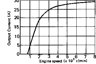
| Type | A.C. generator |
| Model/Manufactu rer | LD119-08/HITACHI |
| Output | 14V 19A at 5,000 r/min |
| Field (inner! coil resistance (Color) | 4.00 + 10% at 20°C (68°F) (G - Br) |
| Armature (Outer) coil resistance (Color) | 0.46O ± 10% at 20° C (68° F) (W - W) |
| Brush - Overall length | 17 mm (0.67 in) |
| — Wear limit | 10 mm (0.39 in) |
| — Spring pressure | 190~360g(6.7~ 12.7 oz) |
|
Voltage regulator: |
|
| Type | Field control type |
| Model/Manufacturer | SH233-12/SHINDENGEN |
| No load regulated voltage | 14.2 ~ 14.8V |
|
Rectifier: |
|
| Model/Manufacturer | SH233-12/SHINDENGEN |
| Capacity | 35A |
| Withstand voltage | 320V |
|
Battery: |
|
| Capacity | 12V 14AH |
| Specific gravity | 1,280 |
| Electric starter system: | Constant mesh type |
| Starter motor - Model/Manufacturer | ADB4D2/NIPPONDENSO |
| - Output | 0.6 kW |
| Armature coil resistance | 0.014O ± 6% at 20°C (68°F) |
| Brush-overall length | 12 mm (0.47 in) |
| Limit | < 8.5 mm (0.33 in) > |
| Spring pressure | 800+ 150 g (28.22 ± 5.29 oz) |
| Commutator dia. | 28 mm (1.1 in) |
| Wear limit | <27mm (1.06 in) > |
| Mica undercut | 0.6 ± 0.2 mm (0.024 + 0.008 in) |
| Starter switch manufacturer | HONDA LOCK |
| Amperage rating | 150A |
| Coil winding resistance | 3.412 at 20°C (68°F) |
|
Horn: |
|
| Type/Quantity | Plane type/2 |
| M odel /Ma nuf actu rer | CF-12/NIKKO |
| Maximum-amperage | 2.5A |
|
Flasher relay: For Germamy |
|
| Type | Condenser type Tramsistor type |
| Model/Manufacturer | FU249CD/NIPPONDENSO FJ245ED/NIPPONDENSO |
| Self cancelling device | YES NO |
| Flasher frequency | 85 ± 10 cycle/min <— |
| Wattage | 21Wx2+3.4W «- |
|
Self-cancelling unit |
|
| Model/Manufacturer | 1A0/MATSUSHITA |
|
Oil level switch: |
|
| Manufacturer | IMIPPONDENSO |
|
Fuel gauge: |
|
| Manufacturer | NIPPON SEIKI |
| Sender unit resistance — Full | 7O±70%at20°C(68°F) |
| — Empty | 95O±80%at20°C(68°F) |
|
Starting circuit cut off relay: |
|
| Model/Manufacturer | 12R/OMRON |
| Coil winding resistance | 75ft ± 10%at20°C(68°F) |
|
Circuit breaker: |
|
| Type | Fuse |
|
Amperage for individual circuit: |
|
| Main | 30A/1 |
| Headlight | 20A/1 |
| Signal | 10 A/1 |
| Ignition | 10 A/1 |
| Reserve | 30A/1 and 20A/1 |
General Torque Specifications
General Torque SpecificationsThis chart specifies torque for standard fasteners with standard I.S.O. pitch threads. Torque specifications for special components or assemblies are included in the applicable sections of this book. To avoid warpage, tighten multi-fastener assemblies in a crisscross fashion, in progressive stages, until full torque is reached. Unless otherwise specified, torque specifications call for clean, dry threads. Components should be at room temperature.
|
A (Nut) |
B (Bolt) |
General torque specifications |
||
|
Nm |
m-kg |
ft lb |
||
|
10 mm |
6 mm |
6 |
0.6 |
4.5 |
|
12 mm |
8 mm |
15 |
1.5 |
11 |
|
14 mm |
10 mm |
30 |
3.0 |
22 |
|
17 mm |
12 mm |
55 |
5.5 |
40 |
|
19 mm |
14 mm |
85 |
8.5 |
61 |
|
22 mm |
16 mm |
130 |
13.0 |
94 |
A: Distance across flats B: Outside thread diameter
DEFINITION OF UNITS
|
Unit |
Read |
Definition |
Mesure |
|
mm |
Millimeter |
10-3 meter |
Length |
|
kg |
kilogram |
103 gram |
Weight |
|
N |
Newton |
1 kg x m/sec2 |
Force |
|
Nm |
Newton meter |
N x m |
Torque |
|
Pa |
Pascal |
N/m2 |
Pressure |
|
L |
Liter |
Volume or Capacity |
|
|
r/min |
Rotation per minute |
Engine Speec |