Chapter 6. Electrical
Chapter 6. ElectricalElectrical Components
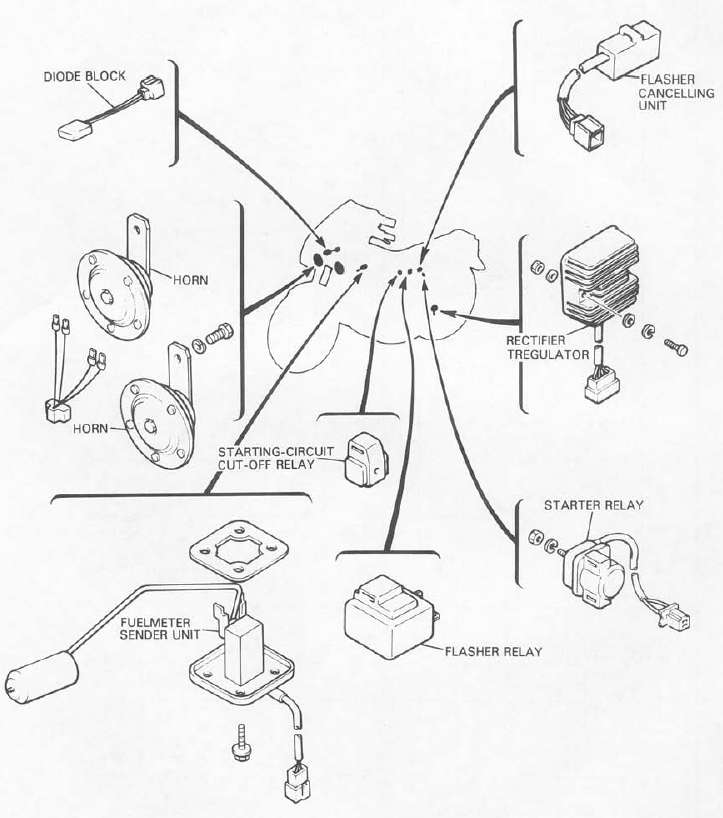
Electrical ComponentsELECTRICAL COMPONENTS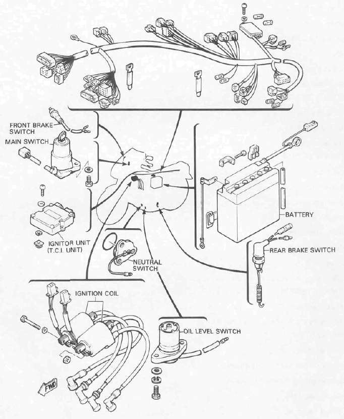
Wiring Diagram -- Models WITHOUT sidestand switch
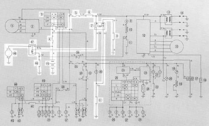
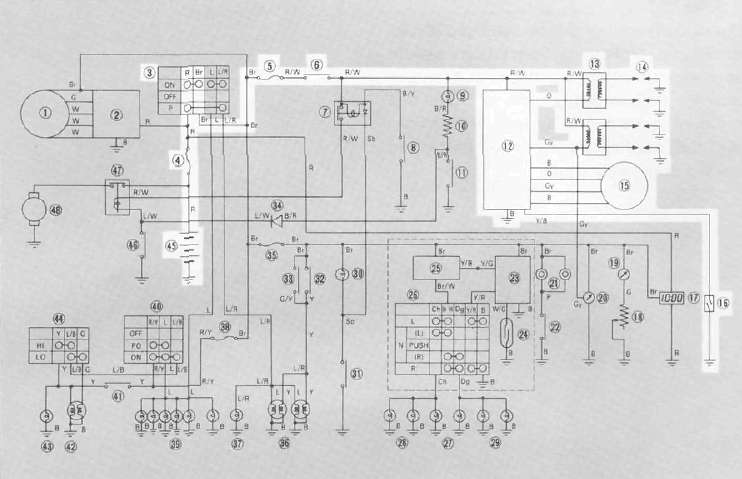
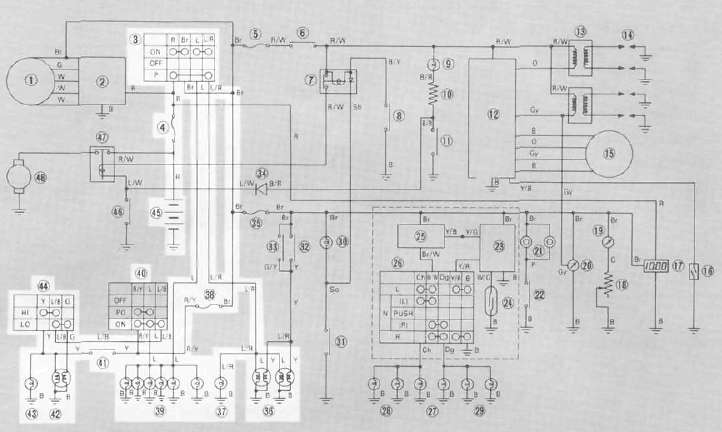
Wiring Diagram -- Models WITHOUT sidestand switchXJ900RK CIRCUIT DIAGRAM Models Without Side Stand Switch
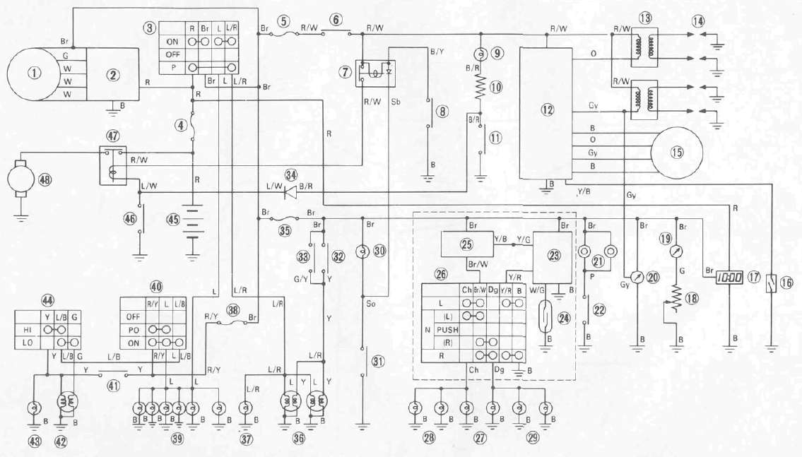
| 1. | A. C. Generator | 2. | Rectifier with regulator |
| 3. | Main switch | 4. | Fuse (Main) |
| 5. | Fuse (Ignition) | 6. | "ENGINE STOP" switch |
| 7. | Starting-circuit cut-off relay | 8. | Clutch switch |
| 9. | "OIL" indicator light | 10. | Resistor |
| 11. | Oil level switch | 12. | Ignitor unit |
| 13. | Ignition coil | 14. | Spark plug |
| 15. | Pick-up coil | 16. | Over revolution switch |
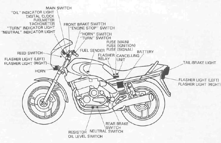
| 17. | Digital clock | 18. | Fuel sender |
| 19. | Fuelmeter | 20. | Tachometer |
| 21. | Horn | 22. | "HORN" switch |
| 23. | Cancelling unit | 24. | Reed switch |
| 25. | Flasher relay | 26. | "TURN" switch |
| 27. | "TURN" indicator light | 28. | Flasher light (Left) |
| 29. | Flasher light (Right) | 30. | "NEUTRAL" indicator light |
| 31. | Neutral switch | 32. | Rear brake switch |
| 33. | Front brake switch | 34. | Diode |
| 35. | Fuse (Signal) | 36. | Taillight |
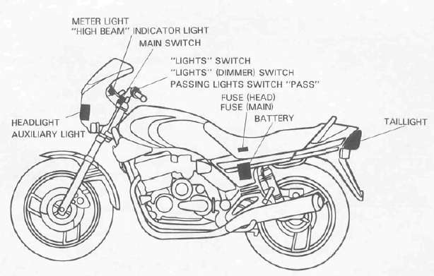
| 37. | Auxiliary light | 38. | Fuse (Head) |
| 39. | Meter light | 40. | "LIGHTS" switch |
| 41. | Passing light switch "PASS" | 42. | Headlight |
| 43. | "HIGH BEAM" indicator light | 44. | "LIGHTS" (Dimmer) switch |
| 45. | Battery | 46. | Starter switch |
| 47. | Starter relay | 48. | Starter motor |
COLOR CODE
| Br | Brown | Y | Yellow | L | Blue |
| R | Red | Dg | Dark Green | P | Pink |
| W | White | Ch | Chocolate | 0 | Orange |
| B | Black | Sb | Sky Blue | G | Green |
| Y/B | Yellow/Black | Y/R | Yellow/Red | E | Ground |
| Br/W | Brown/White | R/W | Red/White | B/R | Black/Red |
| Y/G | Yellow/Green | L/R | Blue/Red | Gy | Grey |
| W/G | White/Green | R/Y | Red/Yellow | G/Y | Green/Yellow |
| L/W | Blue/White | W/G | White/Green | B/Y | Black/Yellow |
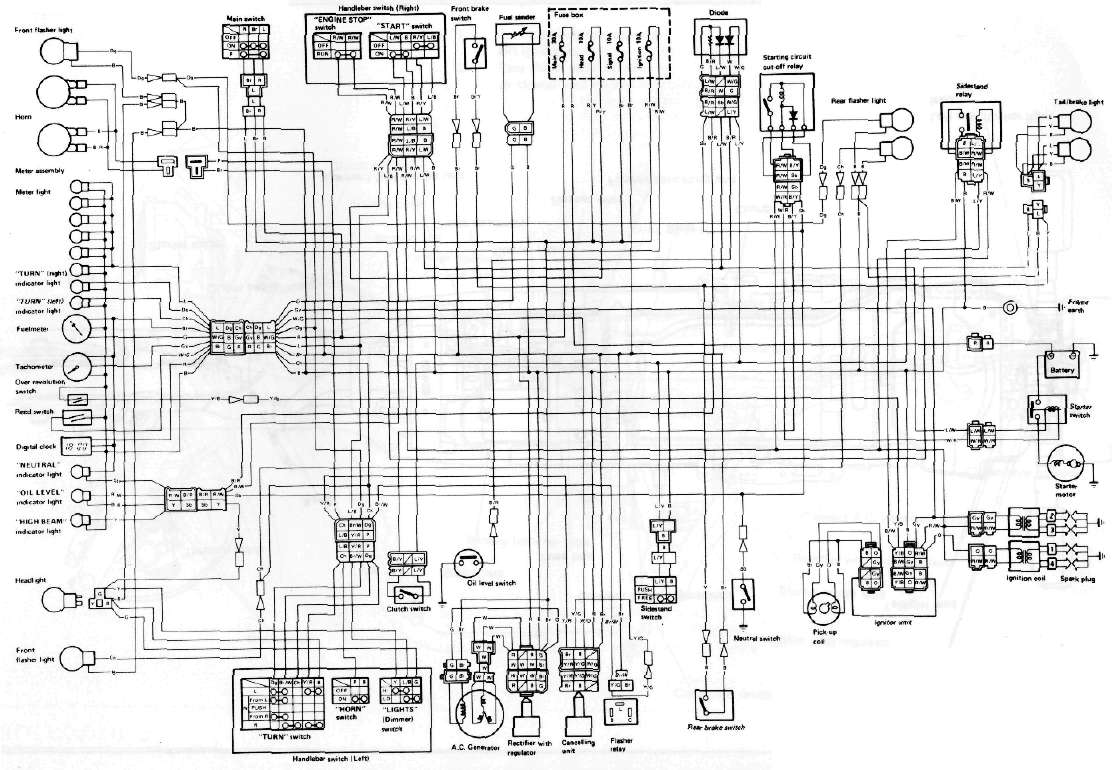
Wiring Diagram -- Models WITH sidestand switch
Wiring Diagram -- Models WITH sidestand switch
Electric Starting System
Electric Starting SystemCircuit diagram
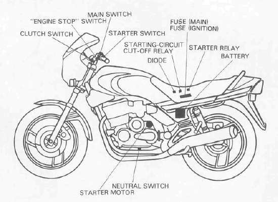
Starter motor
1. Removal
See Engine Dissassembly, Starter and Generator.
2. Inspection and repair
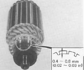
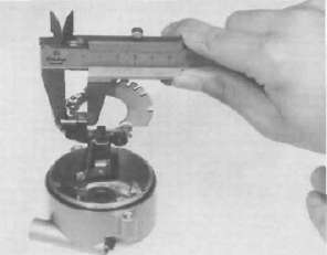
a. Check the outer surface of the commutator. If its surface is dirty, clean with # 600 grit sand paper.
b. The mica insulation between commutator segments should be 0.4 — 0.8 mrn (0.02 — 0.03in) below the segment level. If not, scrape to proper limits with appropriately shaped tool. (A hack saw blade can be ground to fit.)
NOTE: Mica insulation of commutator must be undercut to ensure proper operation of commutator.
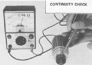
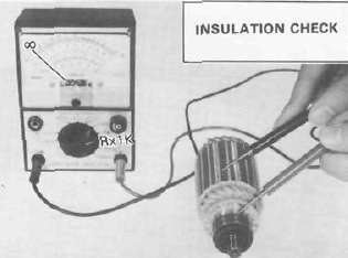
c. The starter's armature coil should be checked with an ohm meter for insulation breakdown (shorting to each other or to ground) and for continuity. Reference figure is given below.
Coil resistanec: Armature coil: 0.014 Ω ± 6 % at 20°C (68°F)
d. Check the front and rear cover bearings for damage. If damaged, the starter assembly must be replaced.
e. Check brush length. Replace brush if at or near, limits.
Minimum brush length: 8.5 mm (0.33 in)
f. Check brush spring pressure. Compare it with a new spring. Replace the old spring if it is weak.
Starter relay
1. Inspection
a. Disconnect starter relay leads at the relay.
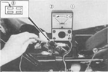
b. Connect pocket tester leads to the relay terminals (ohms x 1 scale).
c. Turn ignition to "ON" position, engine stop switch to "RUN" and change lever to "NEUTRAL".
d. Push the starter switch. The relay should click once and the scale should read zero if it does not read zero, the relay must be replaced.
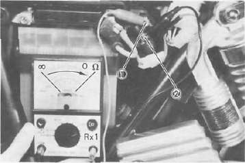
1 Battery lead (+) 2. Starter motor lead
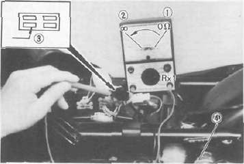
e. If the relay does not click, check the leads from the starter switch and from the battery (white/red, blue/white). Turn the ignition off. Use (ohms x 1) scale on tester. The resistance between these leads should be no more than 3.4 ohms. If there is more resistance, the relay should be replaced.
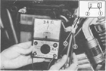
1 Blue/White 2 White/Red
Starting-circuit cut-off relay
1. Inspection
a. Remove the seat.
b. Remove the starting-circuit cut-off relay from the electrical components holding plate, and disconnect the connector.
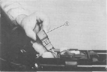
1 Starting-circuit cut-off relay
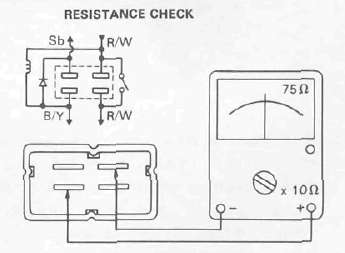
c. Check the resistance of the relay coil windings with the pocket tester. If the resistance is not within specification, replace the relay.
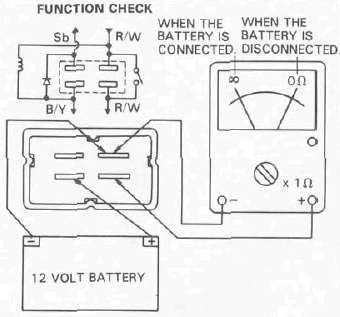
d. Check the relay function with a 12 volt battery and the pocket tester. Connect the leads as shown in the illustration. If the resistance readings do not equal those shown in the illustration, replace the relay.
Neutral switch
Diode
1. Inspection
a. Remove the seat.
b. Remove the diode from the electrical components holding plate, and disconnect the connector.
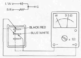
c. Check the resistance of the diode with the pocket poster as shown in the illustration. If the resistance is not specification, replace the diode.
NOTE: Only the Yamaha Pocket Tester will give a 9.5 Ωreading when testing continuity. The particular characteristics of other testers will vary the continuity test readings.
1. Inspection
a. Remove the seat.
b. Disconnect the 4-pin connector from the main wire harness.
c. Connect the pocket tester leads as shown, and set the tester selector to ohm x 1.
When the transmission is in neutral, the tester should read zero ohms. When the transmission is in gear, the tester should read infinity.
1. Neutral 2 In gear 3. Sky blue 4 Ground
Clutch switch
1. Inspection
a. Remove the seat.
b. Disconnect the 4-pin connector from the main wire harness.
c. Connect the pocket tester leads as shown, and set the tester slector to ohm x 1.
When the clutch is disengaged, the tester should read zero ohms. When the clutch is engaged, the tester should read infinity.
1. Disengaged 2. Engaged 3. Black/Yellow 4. Ground
Charging System
Charging SystemCircuit diagram 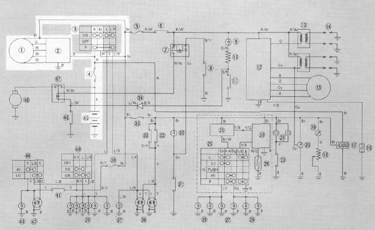
A. C. Generator
1. Checking method
a. Connect D. C. voltmeter to the battery terminals.
b. Start the engine.
c. Accelerate engine to approximately 2,000 r/min or more and check generated voltage,
Generated voltage:
14.5 ± 0.3 V at 20°C (68°F)

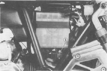
1 Battery
d. If the indicated voltage cannot be reached, then perform the tests in step 2.
CAUTION: Never disconnect leads from the battery while the generator is in operation. If the battery is disconnected, the voltage across the generator terminals will increase, damaging the semiconductors.
2. Resistance test of field coil and stator coil
a. Remove the seat. Disconnect the 2-pin connector and 3-pin connector from the A. C. Generator.
b. Check the resistance between terminals. If resistance is out of specification, coil is broken. Check the coil connections. If the coil connections are good, then the coil is broken inside and it should be replaced.
Field coil resistance (Green-Brown): 4.0 Ω ± 10 % at 20°C (68°F)
Stator coil resistance (White-White): 0.46 Ω ± 10 % at 20°C (68°F)
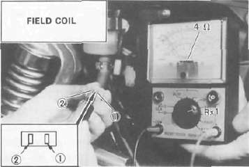
1 Brown 2. Green
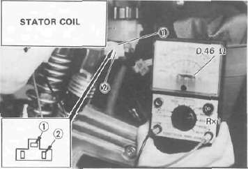
1. White 2. White
Voltage regulator
The AC Voltage Regulator is a small and, normally, very reliable component. Due to its construction, it is lightweight and free from the wear and misadjustment associated with mechanical voltage regulators. If the following inspection reveals that the regulator is faulty, it cannot be adjusted and must be replaced.
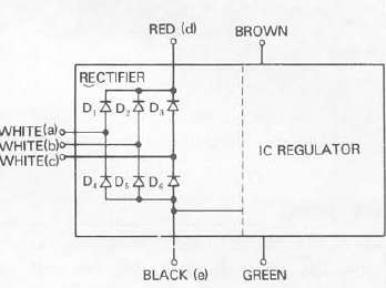
1. Rectifier with regulator
1. Checking AC Voltage regulator
a. Remove the seat.
b. Remove the left side cover.
c. Measure the specific gravity of the battery fluid. If it is less than 1.260, remove the battery and recharge until it is more than 1.260.
d. Check the battery terminals and couplers for looseness.
e. Connect two Yamaha pocket testers to the regulator coupler as illustrated.
CAUTION: Be careful not to let the tester leads short circuit when connecting them to the regulator snap connector leads.
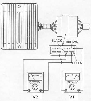
f. Turn the main switch on. Make sure that V2 is less than 1.8V.
NOTE: Do not turn on lights or signals.
g. Make sure that V2 gradually increases up to 9 - 11V when the engine is started and its revolutions go up.
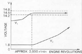
h. Make sure that V, maintains the level of 14.2 — 14.8 V even when engine revolutions increase.
i. If these levels are not maintained, the regulator is defective and must be replaced.
2. Checking the silicon rectifier
a. Check the silicon rectifier as specified using the Yamaha pocket tester.
|
Checking element |
Pocket tester connecting point |
Good |
Shorted |
Open |
|
| (+) (red) | (-)
(black) |
||||
|
D, |
d | a | O | O | X |
| a | d | x | 0 | X | |
|
D2 |
d | b | O | o | X |
| b | d | X | o | X | |
|
D3 |
d | c | O | o | X |
| c | d | X | o | X | |
|
D4 |
a | e | O | o | X |
| e | a | X | 0 | X | |
|
D5 |
b | e | O | o | X |
| e | b | X | o | X | |
|
D6 |
c | e | O | o | X |
| e | c | X | o | X | |
O: Continuity
x: Discontinuity (∞)
b. Even if only one of the elements is broken, replace the entire assembly.
CAUTION: The silicon rectifier can be damaged if subjected to overcharging. Special care should be taken to avoid a short circuit and/or incorrect connection of the positive and negative leads at the battery. Never connect the rectifier directly to the battery to make a continuity check.
Ignition System
Ignition SystemCircuit diagram
Description
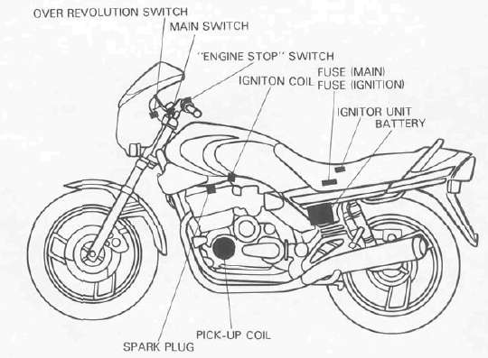
This model is equipped with a battery operated, fully transistorized breakerless ignition system. By using magnetic pick-up coils the need for contact breaker points is eliminated. This adds to the dependability of the system by eliminating frequent cleaning and adjustment of points and ignition timing. This T. C. I. (Transistor Control Ignition) unit in corporates an automatic advance circuit controlled by signals generated by the pick-up coil. This adds to the dependability of the system by eliminatng the mechanical advancer. This T. C. I. system consists of two main units; a pick-up unit and ignitor unit.
Operation
The T. C. I. functions on the same principle as a conventional D. C. ignition system with the exception of using magnetic pick-up coils and a transistor control box (T. C. I.) in place of contact breaker points.
1. Pick-up unit
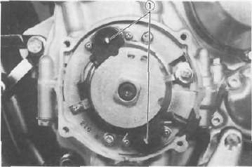
1 Pick-up coils
This unit consists of two pick-up coils and a magneto mounted on the crank-case (L. H.). When the reluctor (timing plate) projection passes the pick-up coil, the two signals are generated at the pick-up coil and transmited to the ignitor unit as a signal. The full ignition advance is determined by the width of the reluctor (timing plate) projection.
2. Ignitor unit
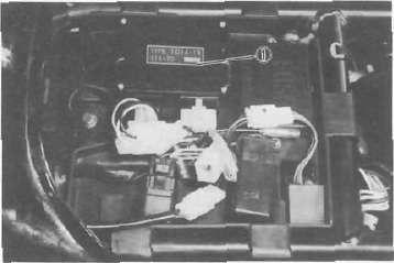
1 Ignitor unit (T.C.I, unit)
This unit has such functions of wave form, duty control, switching, electrical ignition advance, and etc. The ignition timing is advanced electrically using two signals from the pick-up coil. The duty control circuit is provided to control the on time period of the primary ignition current to reduce the electrical consumption. This unit also incorporates a protective circuit for the ignition coil. If the ignition switch is turned on and the crankshaft is not turned, the protective circuit stops current flow to the primary coil within a few seconds. When the crankshaft is turned over, the current is turned on again by the signals generated by the pick-up coils.
CAUTION: Do not run the engine without any spark plug cap(s) in place. Due to the high secondary voltage, it is possible to damage the internal insulation of the secondary coil.
Inspection
The entire ignition system can be checked for misfire and weak spark using the Electro Tester. If the ignition system will fire across a sufficient gap, the entire ignition system can be considered good. If not, proceed with individual component tests until the problem is found. 1. Warm up engine thoroughly so that all electrical components are at operating temperature.
2. Stop the engine and connect the tester as shown.
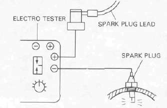
3. Start the engine and increase the spark gap until misfire occurs. (Test at various r/min between idle and red line.)
Minimum spark gap: 6 mm (0.24 in)
CAUTION: Do not run engine in neutral above 6,000 r/ min for more than 1 or 2 seconds.
Troubleshooting Chart
| Check entire ignition connections. |
Poor connection ► |
Correct.
|
| ▼ OK | ||
| Check battery voltage and specific gravity. |
Low voltage/specific gravity ► |
Recharge battery.
|
| ▼ OK | ||
| Check fuse and fuse connections. |
Weak connection or open circuit ► |
Correct connection or replace fuse.
|
| ▼ OK | ||
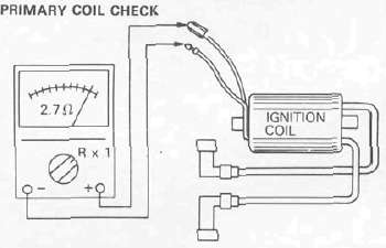
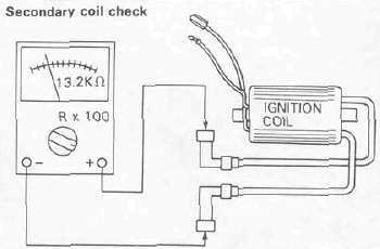
| Check ignition coil resistance (primary and secondary).
Primary: 2.7Ω ± 10%@20°C (68°F) Secondary: 13.2KΩ ± 20%@20°C (68° F) |
If other than specified ► |
Replace ignition coil.
|
| ▼ OK |
If other than specified ► |
Replace pickup coil assembly.
|
| Check pickup coil resistance.
Pickup coil: 120Ω ± 10% at 20°C (68°F) |
||
| ▼ OK | ||
| Check operation of sidestand switch (if fitted) and relay. |
Faulty ► |
Check sidestand relay sidestand switch, diode and neutral switch.
|
| ▼ OK | ||
| TCI unit is faulty, replace unit. |
Ignition coil
1. Coil spark gap test.
a. Remove the fuel tank and disconnect the ignition coil from wire harness and spark plugs.
b. Connect the Electro Tester as shown.
CAUTION: When testing twin secondary lead coils, one lead must always be grounded and the other lead may not exceed the maximum spark gap because the insulation on the secondary windings may be destroyed by the overly high voltages that can be generated.
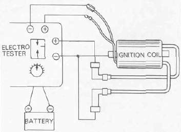
c. Connect fully charged battery to tester.
d. Turn on spark gap switch and the increase gap to maximum unless misfire occurs first.
Minimum spark gap: 6 mm (0.24 in)
2. Direct current resistance test
Use a pocket tester or equivalent ohm-meter to determine resistance and continuity of primary and secondary coil windings.
Primary coil resistance:
2.7 Ω ± 10% at 20°C (68°F) Secondary coil resistance:
13.2 KΩ ± 20 % at 20°C (68°F)
Pick-up coil
1. Inspection
a. Remover the seat.
b. Disconnect the pick-up coil leads from the ignitor unit.
c. Check the resistance of the pick-up coil windings with the pocket tester. If the resistance is not within specification, replace the pick-up coil assembly.
Pick-up coil resistance:
1 20 Ω ± 10 % at 20°C (68°F)
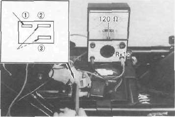
1 Black 2 Orange 3 Brown
Spark plug
The life of a spark plug and its discoloring vary according to the habits of the rider. At each periodic inspection, replace burned or fouled plugs with new ones of the specified type. It is actually economical to install new plugs often since it will tend to keep the engine in good condition and prevent excessive fuel consumption.
1. Inspection
a. Inspect and clean at the specified intervals and replace as required.
b. Clean the electrodes of carbon and adjust the electrode gap to the specification.
2. Installation
Be sure to use the proper reach, type and electrode gap plug(s) as a replacement to avoid overheating, fouling or piston damage.
Type: BPR8ES (NGK) Electrode gap:
0.7 — 0.8 mm (0.028 — 0.031 in) Tightening torque:
20 Nm (2.0 mkg, 14ft-b)
Lighting System
Lighting SystemCircuit diagram
Lighting system tests and checks
The battery provides power for operation of the headlight, taillight, and meter lights. If none of the above operates, always check battery voltage before proceeding further. Low battery voltage indicates either a faulty battery, low battery electrolyte, or a defective charging system. See page 6-9 "CHARGING SYSTEM" for checks of battery and charging system. Also check fuse condition. Replace any "open" fuses. There are individual fuses for various circuits (see complete Circuit Diagram).
NOTE: Check the headlight bulb first before performing the following check.
1. Headlight does not come on. (High and/or low beam)
|
Check for voltage (12V) on "R/Y" lead at "LIGHTS" switch connector. |
No voltage |
Check wiring circuit from fuse to "LIGHTS" switch connector. |
|
Voltage OK ▼ |
||
|
Check for voltage (12V) on "L/B" lead at "LIGHTS" (Dimmer) switch connector. |
No voltage |
Check "LIGHTS'* switch and wiring circuit from "LIGHTS" switch to "LIGHTS" (Dimmer) switch connector. |
|
Voltage OK ▼ |
||
|
Check for voltage (12V) on "Y" or "G" leads at headlight bulb socket. |
No voltage |
"LIGHTS" (Dimmer) switch and/or wiring circuit from "LIGHTS" (Dimmer) switch to headlight bulb socket is faulty Repair. |
2. Taillight does not come on.
When the "LIGHTS" switch is "PO" or "ON" and the main switch is "ON" or "P" positions.
|
Check for voltage (12V) on "L" lead at "LIGHTS" switch connector |
No voltage ► |
|
| Voltage OK ▼ | ||
|
Check for voltage (12V) on "L" lead at main switch connector. |
No voltage |
Wiring circuit from "LIGHTS" switch to main switch connector is faulty, repair. |
| Voltage OK ▼ | ||
|
Check for voltage (12V) on "L/R" lead at main switch connector. |
No voltage |
Main switch is faulty, replace |
|
Voltage OK ▼ |
||
|
Check for voltage (12V) on "L" lead at taillight bulb socket. |
No voltage |
Wiring circuit from main switch to taillight bulb socket is faulty. repair. |
3. Auxiliary light does not come on.
When the "LIGHTS" switch is "PO" or "ON" and the main switch is "ON" or "P" position.
|
Check for voltage (12V) on "L" lead at "LIGHTS" switch connector. |
No voltage |
"LIGHTS" switch is faulty, replace. |
| Voltage OK ▼ | ||
|
Check for voltage (12V) on "L" lead at main switch connector. |
No voltage |
Wiring circuit from "LIGHTS" switch to main switch connector is faulty, repair. |
| Voltage OK ▼ | ||
|
Check for voltage (12V) on "L/R" lead at main switch connector. |
No voltage |
Main switch is faulty, replace. |
| Voltage OK ▼ | ||
|
Check for voltage (12V) on "L/R" lead at auxiliary light bulb socket. |
No voltage |
Wiring circuit from main switch to auxiliary light bulb socket is faulty, repair. |
Signal System
Signal SystemSIGNAL SYSTEM Circuit diagram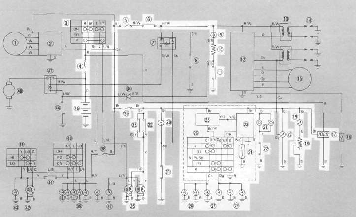
Signal system tests and checks
The battery provides power for operation of the horn, brakelight, indicator lights and flasher light. If none of the above operates, always check battery voltage before proceeding further. Low battery voltage indicates either a faulty battery, low battery water or a defective charging system. See page 6-9 "CHARGING SYSTEM" for checks of battery and charging system. Also check fuse condition. Replace any "open" fuses. There are individual fuses for various circuits (see complete Circuit Diagram).
1. Horn does not work
|
Check for voltage (12V) on "Br" lead at horn terminal. |
No voltage ► |
Check wiring circuit from fuse to horn terminal. |
|
Voltage OK ▼ |
||
|
Check for voltage on "P" lead at "HORN" switch connector. |
No voltage ► |
Wiring circuit from horn to "HORN" switch is faulty, repair. |
|
Voltage OK ▼ |
||
|
Check for continuity of "HORN" switch. |
No continuity |
"HORN" switch is faulty, replace. |
|
Continuity ▼ |
||
|
Adjust horn, replace if damaged. |
||
2. Brake light does not work a. Front brake
|
Check for voltage (12V) on "Br" Lead at front brake switch connector |
No voltage |
Check wiring circuit from fuse to brake switch connector. |
|
Voltage OK ▼ |
||
|
Check for voltage (12V) on "Gy" lead at front brake switch connector while applying brake. |
No voltage |
Front brake switch is faulty, replace |
|
Voltage OK ▼ |
||
|
Check for voltage (12V) on "Y" lead at brake light bulb socket while applying brake. |
No voltage |
Wiring circuit from brake switch to Brake light bulb socket is faulty, repair. |
b. Rear brake
|
Check for voltage (12V) on "Br" lead at rear brake switch connector. |
No voltage |
Check wiring circuit from fuse to brake switch connector. |
|
Voltage OK ▼ |
||
|
Check for voltage (12V) on "Y" lead at rear switch connector while applying brake. |
No voltage |
Rear brake switch is faulty or maladjustment, replace or adjust. |
|
Voltage OK ▼ |
||
|
Check for voltage (12V) on "Y" lead at brake light bulb socket while applying brake, |
No voltage |
Wiring circuit from brake switch to brake light bulb socket is faulty, repair. |
3. Flasher lights (left and/or right) do not work
|
Check for voltage (12V) on "Br" lead at flasher relay terminal. |
No voltage |
Check wiring circuit from fuse to flasher relay terminal. |
|
Voltage OK ▼ |
||
|
Check for voltage (12V) on "Br/W" lead at flasher relay terminal. |
No voltage |
Flasher relay is faulty, replace. |
|
Voltage OK ▼ |
||
|
Check for voltage (12V) on "Br/W" lead at "TURN" switch connector. |
No voltage |
Wiring circuit from flasher relay to "TURN" switch is faulty, repair. |
|
Voltage OK ▼ |
||
|
Check for voltage (12V) on "Ch" and/or "Dg" lead at "TURN" switch connector. |
No voltage |
"TURN" switch is faulty, replace. |
|
Voltage OK ▼ |
||
|
Check for voltage (12V) at left and/or right flasher (front and/or left bulb socket. |
No voltage |
Wiring circuit from "TURN" switch to flasher bulb is faulty, repair. |
Self-cancelling flasher system
1. Description
The self-cancelling flasher system turns off the turn signal after a period of time or distance involved in turning or changing lanes. Generally, the signal will cancel after either 10 seconds, or 150 meters (490 feet), whichever is greater. At very low speed, the function is determined by distance; at high speed, especially when changing speeds the cancelling determination is a combination of both times and distance.
2. Operation
The handlebar switch has three positions:
L (left), OFF, and R (right). The switch lever will return to the "OFF" position after being pushed to L or R, but the signal will function. By pushing the lever in, the signal may be cancelled manually.
3. Inspection
If the flasher self-cancelling system should become inoperative, proceed as follows: a. Pull of the 6-pin connector from the flasher cancelling unit, and operate the handlebar switch.
If the signal operates normally in L, R, and OFF, the following are in good condition.
1) Flasher relay
2) Bulb
3) Lighting circuit
4) Handlebar switch light circuit
If 1) through 4) are in good condition, the following may be faulty:
1) Flasher cancelling unit.
2) Handlebar switch reset circuit
3) Speedometer sensor circuit
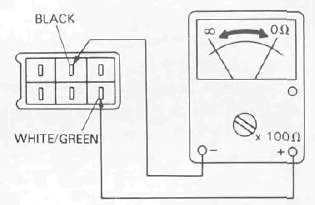
b. Pull off the 6-pin connector from the flasher cancelling unit, and connect a tester (ohms x 100 range) across the white/green and the black leads on the wire harness side. Turn the speedometer shaft If the tester needle swing back and forth between 0 and co, the speedometer sensor circuit is in good condition. If not, the sensor to wire harness may be inoperative.
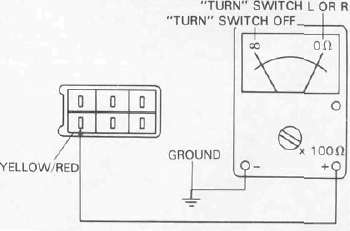
c. Pull the 6-pin connector from the flasher cancelling unit Check if there is continuity between the yellow/red lead on the wire harness side and the chassis.
"TURN" switch OFF: oo "TURN" switch L or R: 0 il
If the tester needle does not swing as indicated above, check the handlebar switch circuit and wire harness.
d. If no defect is found with the above three check-ups and the flasher cancelling system is still inoperative, replace the flasher cancelling unit.
e. If the signal flashes only when the handlebar switch lever is turned to L or R and it turns off immediately when the handlebar switch lever returns to center, replace the flasher cancelling unit
Sensors and Switches
Sensors and SwitchesFuel sender unit
1. Inspection
a. Remove the sender unit from the fuel tank.
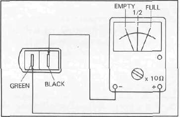
b. Use a pocket tester (with ohm x 10 scale) for this check. Connect the pocket tester leads across the green lead and the black lead of the sender unit. The meter should show the following resistance at the specified fuel level. If not replace the sender unit.
|
Fuel sender resistance |
|
| Full | 2—12Ω |
| 1/2 | 40Ω |
| Empty | 87.5 — 102.5 Ω |
Oil level switch
1. Inspection
a. Remove the oil level switch from the engine.
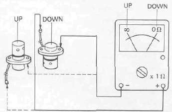
b. Use a pocket tester (with ohm x 1 scale) for this check.
Connect the pocket tester lead as shown.
When the oil level switch stands up right the tester should read infinity. When the oil level switch stands up side down, the tester should read 0 ohms.
Tachometer
1. Description
This model has been equipped with an electric tachometer. This tachometer receives its impulses from one of the stator leads of the alternator.
2. Inspection
a. If the tachometer should become inoperative, the following troubleshooting steps will be useful.
1) Remove the headlight rim.
2) Turn the ignition switch to the "ON" position.
3) Inside the headlight shell disconnect the tachometer leads from the main harness.
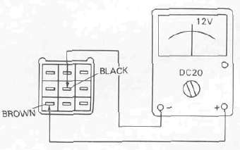
Use a pocket tester to check and set the meter selector to the "DC 20" position.
| Connect tester leads between brown and black leads from main harness.
Meter should show 12 volts D. C. |
Less than 12 volts or no voltage ► |
Weak connection or open circuit between fuse and main harness |
| YES ▼ |
||
| Replace tachometer assembly | ||
Digital clock
1. Inspection
If the digital clock should become inoperative, the following troubleshooting steps will be useful.
a. Remove the headlight rim.
b. Turn the ignition switch to the "ON" position.
c. Inside the headlight shell disconnect the digital clock leads from the main harness. Use a pocket tester to check and set the meter selector to the "DC 20" position.
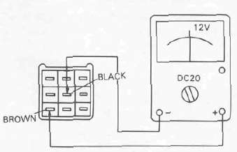
| Connect tester leads between brown and black leads from main harness.
Meter should show 12 volts D. C |
Less than 12 volts or no voltage ► |
Weak connection or open circuit between fuse and main harness |
| YES ▼ |
||
| Replace digital clock assembly | ||
2. Adjustment
This digital clock always show the time regardless of the main switch position.
To set the time:
Turn ignition "ON"
Set hour by pushing or holding the "H" switch.
Set minutes by pushing or holding the "M" switch.
NOTE: If setting the clock after the power source has been interupted (eg: disconnected battery, blown fuse) It may be necessary to first hold the "H" switch for 10 seconds; before setting the correct time.
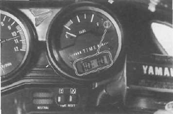
1. Digital clock
Switches
Switches may be checked for continuity with a pocket tester on the "ohm x 1" position.
1. Main switch
|
Switch Position |
Wire Color | |||
| R | Br | L | L/R | |
| OFF | ||||
| ON |  |
 |
||
| P (parking) |  |
|||
2. "ENGINE STOP" switch
| Switch Position | Wire Color | |
| R/W | R/W | |
| RUN |  |
|
| OFF | ||
3. "LIGHTS" switch (right handlebar)
| SwitchPosition | Wire Color | ||
| R/Y | L | L/B | |
| ON |  |
||
| PO |  |
||
| OFF | |||
4. Starter switch (right handlebar)
| Button Position | Wire Color | |
| L/W | B | |
| OFF | ||
| ON |  |
|
5. "LIGHTS" (Dimmer) switch
| Switch Position | Wire Color | ||
| Y | L B | G | |
| HI |  |
||
| LO |  |
||
6. "TURN" switch (left handlebar)
| Switch Position | Wire Color | ||||
| Dg | Br/W | Ch | Y/R | B | |
| R |  |
 |
|||
| R —N |  |
||||
| N — Push | |||||
| L —N |  |
||||
| L |  |
 |
|||
7. "HORN" switch (left handlebar)
| Switch Position | Wire Color | |
| P | B | |
| PUSH |  |
|
| OFF | ||
8. Passing light switch (left handlebar)
| Button Position | Wire Color | |
| Y | R/Y | |
| OFF | ||
| PUSH |  |
|
Battery
BatteryBattery
1. Checking
If the battery shows the following defects, it should be replaced.
a. The battery voltage will not rise to a specific value or no gassing occurs in any cell even after many hours of charging.
b. Sulfation of one or more cells is indicated by the plates turning white or an accumulation of material in the bottom of the cell.
c. Specific gravity readings after a long slow charge indicate a cell to be lower than any others.
d. Warpage or buckling of plates or insulators is evident.
WARNING: Battery fluid is poisonous and dangerous, causing severe burns, etc. Contains sulfuric acid. Avoid contact with skin, eyes or clothing.
Antidote: EXTERNAL-Flush with water. INTERNAL-Drink large quantities of water or milk. Follow with milk of magnesia, beaten egg or vegetable oil. Call physician immediately.
Eyes: Flush with water for 15 minutes and get prompt medical attention. Batteries produce explosive gases. Keep sparks, flame, cigarettes, etc., away. Ventilate when charging or using in enclosed space. Always shield eyes when working near batteries. KEEP OUT OF REACH OF CHILDREN.
2. The service life of a battery is usually 2 to3 years, but lack of care as described below will shorten the life of the battery.
a. Negligence in keeping battery topped off with distilled water.
b. Battery being left discharged.
c. Over-charging with heavy charge.
d. Freezing.
e. Filling with water or sulfuric acid containing impurities.
f. Improper charging voltage or current on new battery.
3. If the motorcycle is not to be used for a long time, remove the battery and have it stored. The following instructions should be observed:
a. Recharge the battery periodically.
b. Store the battery in a cool, dry place.
c. Recharge the battery before reinstalla-tion.
| Battery | YB14L/12V, 14AH |
| Electrolyte | Specific gravity: 1.280 |
| Initial charging current | 1.4 amp for 10 hours (new battery) |
| Recharging current | 10 hours (or until specific gravity reaches 1.280) |
| Refill fluid | Distilled water (to maximum level line) |
| Refill period | Check once per month (or more often, required) |