Engine Disassembly
Engine DisassemblyPickup coil, Shifter, Starter Motor, Generator, and Clutch
Pickup coil, Shifter, Starter Motor, Generator, and ClutchPick-up coil assembly
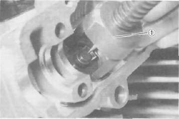
1. Remove the alien bolt that holds the timing plate.
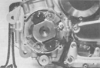
2. Remove the pick-up coil securing screws and remove the pick-up coil assembly.
Shifter
1. Remove the change pedal.
2. Remove the left crankcase cover.
3. Remove the shift lever assembly and shift shaft assembly.
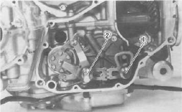
1. Shift lever assembly 2. Shift shaft assembly
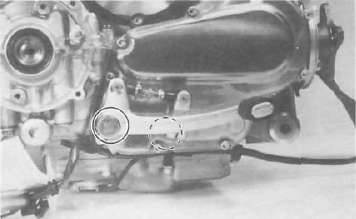
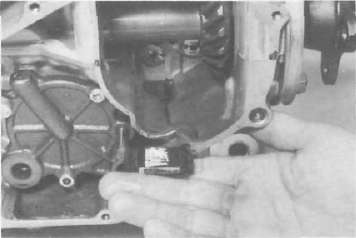
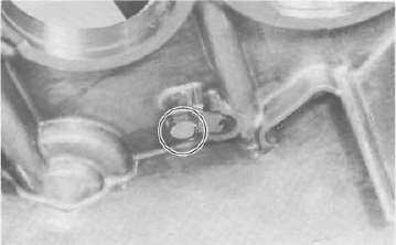
4. Remove the middle gear case oil level maintaining plug.
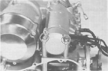
1. Remove the starter motor securing bolts and remove the motor assembly.
2. Remove the generator cover and stator coil assembly.
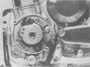
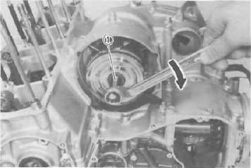
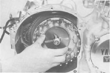
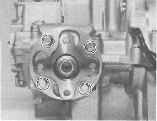
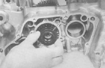
3. Install the rotor holding tool (special tool) on the rotor as shown and remove the rotor holding bolt.
1 Rotor holding tool
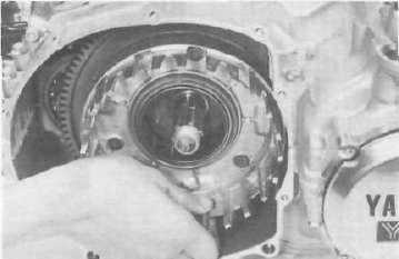
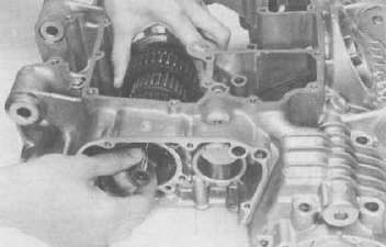
4. Insert the holding tool as shown and insert the rotor puller adapter (special tool) into the rotor shaft and screw in the rotor puller (special tool). Remove the rotor.
1. Rotor puller adapter
1. Rotor puller
Clutch
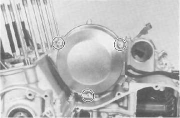
1. Remove right crankcase cover.
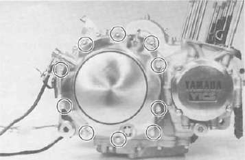
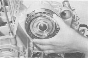
2. Release the tension evenly on the 6 mm bolts and remove the clutch pressure plate and clutch springs.
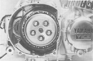
3. Remove the friction plates and clutch plates.
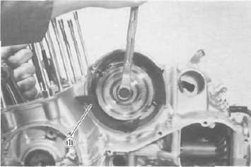
4. Straighten the lock washer tab. Use the clutch boss holder (special tool) to hold the clutch boss and remove the lock nut and lock washer.
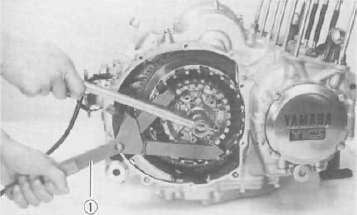
1. Clutch boss holder
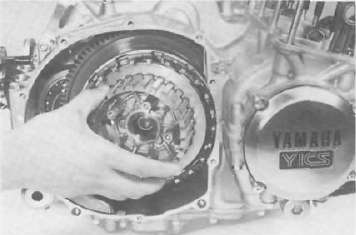
5. Remove the clutch boss and spacer.
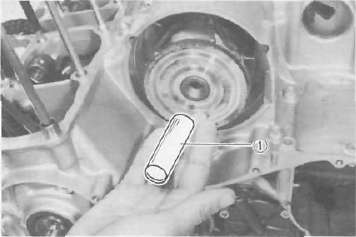
6. Screw in a suitable length of 6 mm bolt into the one of the threaded holes on the collar and pull out the collar and needle bearing from the primary driven gear.
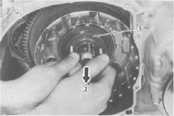
1. Collar 2. Pull
7. Remove the primary driven gear assembly and oil pump drive sprocket
8. Remove the oil collector plate.
Oil pump, Middle gear, and Crankcase
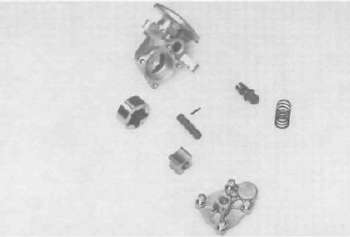
Oil pump, Middle gear, and CrankcaseOil pump removal and disassembly
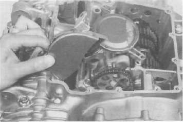
1. Remove the strainer cover. Note the wire harness clip position.
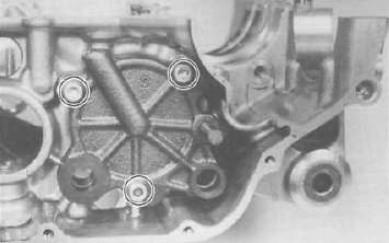
2. Remove the oil pump secruing bolts and remove the sprocket cover and oil pump assembly.
CAUTION: Do not attempt to remove the strainer screen as it is permanently fitted onto the pump housing. If the pump housing and/or any parts of the pump are damaged, the pump assembly must be replaced with a new one.
3. Remove the oil pump driven sprocket.
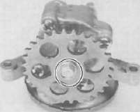
4. Remove the oil pump cover and rotor assembly.
5. Remove the pressure relief valve, spring and plunger.
Middle gear
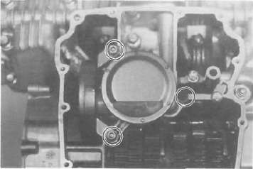
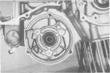
1. Remove the middle driven gear housing holding bolts.
2. Remove the middle driven gear housing assembly and shims.
NOTE: If it is difficult to remove housing assembly, loosen the two crankcase bolts located near the middle driven gear housing.
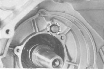
3. Remove "TORX" screws holding the middle drive gear assembly.
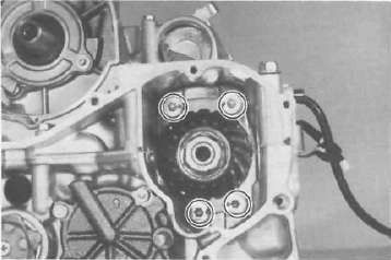
4. Remove the bearing retainers.
Crankcase disassembly
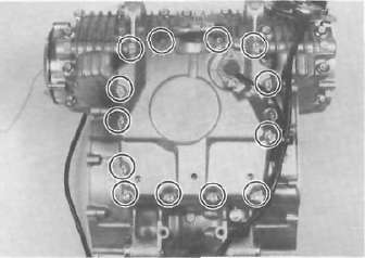
1. Remove the upper crankcase bolts, starting the highest numbered bolt. Turn over the engine and remove the lower crankcase bolts.
CRANKCASE TIGHTENING SEQUENCE
LOWER CASE
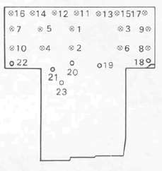
UPPER CASE
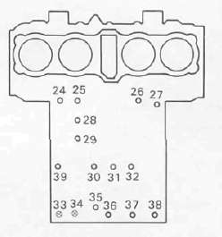
Tightening Torque
8 mm bolt: 24 Nm (2.4 mkg, 17 ft-lb) O .... 6 mm bolt: 12 Nm (1.2 mkg. 8.7 ft-lb)
Separate the lower case from the engine. Use a soft rubber hammer to carefully separate the crankcase.
Upper crankcase
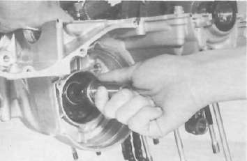
1. Remove the middle drive gear and damper assqmbly.
2. Remove the transmission main shaft assembly.
3. Remove the A. C. G. shaft cover.
4. Remove the oil spray nozzle.
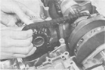
5. Carefully remove the A. C. G. shaft from the gear.
6. Remove the gear from the chain.
7. Straighten the lock washer tab and remove the bolt securing the starter idle gear shaft. Remove the shaft and starter idle gear.
8. Remove the crankshaft.
Lower crankcase
1. Remove the dowel pin and "O-ring".
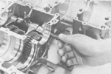
2. Remove the shift fork guide bar and shift forks. The shift forks are identified by numbers cast on their sides.
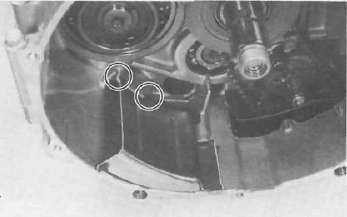
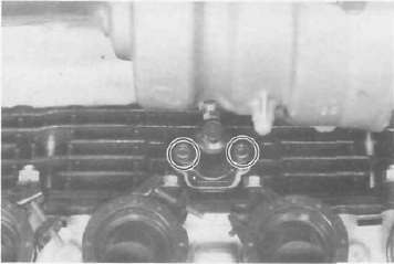
3. Remove the bolt securing the shift cam locating pin and remove the stopper plate and locating pin.
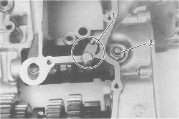
1. Shift cam locating pin 2. Neutral switch
4. Remove the neutral switch.
5. Pull out the shift cam.
6. Remove the driven shaft bearing cover holding screws and remove the bearing cover.
7. Remove the 5th wheel gear from the driven shaft and pull out the driven shaft assembly.
1. 5th wheel gear
Cylinder Head, Cylinder and Piston
Cylinder Head, Cylinder and PistonCylinder head and cylinder
1. Remove the cylinder head cover.
2. Remove the left crankcase cover (pickup coil cover).
3. Remove the cam chain tensioner.
4. Use a 19 mm wrench on the timing plate flats to rotate the crankshaft counterclockwise until the engine is at Top Dead Centre.
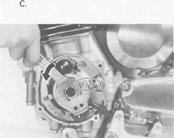
CAUTION: Never use an alien wrench to rotate the crankshaft. Always use the 19 mm flats provided on the timing plate to rotate this engine.
5. Remove the four cam sprocket bolts.
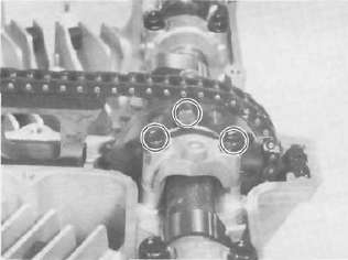
6. Slip each sprocket off its mounting boss on the cam.
CAUTION: From this point on, do not rotate the cam shaft or valve damage may occur. On this, it is not necessary to break the cam chain. However, it can be broken if so desired. It is easier to disassemble the engine without separating the chain.
7. Remove the cam chain guide.
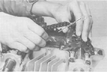
1. Cam cham guide
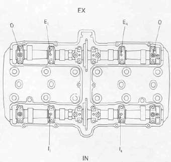
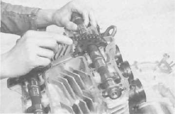
8. Remove the cam caps. Note the location ofthe cam caps as shown. Directional arrows are cast on each cap and point toward the clutch side.
9. Fasten safety wire to the cam chain to prevent its falling into the crankcase cavity.
Slide the camshafts and sprockets from under the chain and remove the camshafts and sprockets.
10. Remove the front cam chain guide.
1. Front cam chain guide
11. Remove the spark plugs.
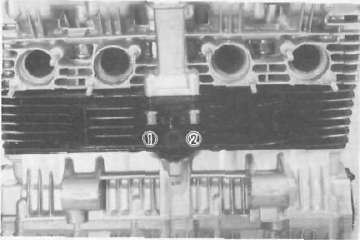
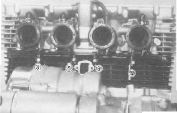
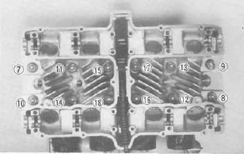
12. Remove the cylinder head bolts and nuts in the numerical order as shown. Start by loosening each nut 1/2 turn until all of the nuts are loose. Remove the cylinder head.
13. Remove the front cylinder holding nut and remove the cylinder assembly. It may be necessary to tap the cylinder lightly to loosen it from the base gasket.
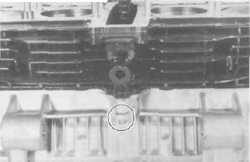
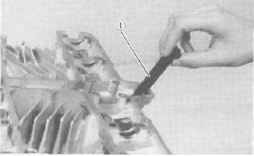
14. Remove the rear cam chain guide by loosening the holding bolt.
1. Hoiding bolt 2 Rear cam chain guide
Cylinder head disassembly
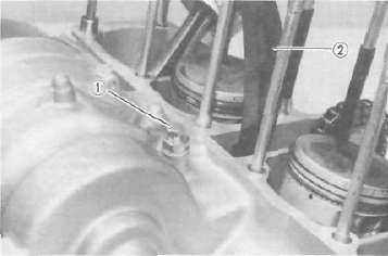
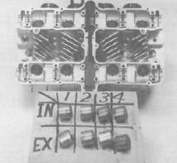
1. Remove the valve lifters and pads. Be careful not to scratch the lifter bodies or lifter bores in the cylinder head. Be very careful to identify each lifters position so that it may be returned to its original place.
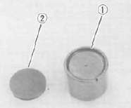
1 Valve lifter 2. Adjusting pad
2. Mount the valve spring compressor on the head and depress each valve spring. Take out the retainer and valve spring with tweezers.
1. Valve spring compressor
3. Remove valves.
NOTE: Deburr any deformed valve stem end. Use an oil stone to smooth the stem end. This will help prevent damage to the valve guide during valve removal.
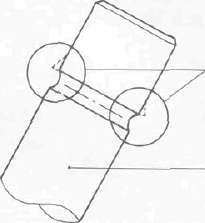
DEBURR VALVE STEM
4. Use a small box to hold the parts and identify the original position of each lifter and valve. Be very careful not to mix the location of these components.
Piston
1. Make each piston to aid in reassembly.
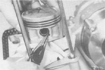
2. Place a clean towel or rag into the cranckcase to keep circlips and material from falling into the engine.
3. Remove piston pin clips, piston pins, and pistons.