Engine Assembly and Adjustment
Engine Assembly and AdjustmentImportant information
1. All gaskets and seals should be replaced when an engine is overhauled. All gasket surfaces and oil seal lips must be cleaned.
2. Properly oil all mating engine and transmission parts and bearings during reassembly.
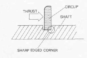
3. All circlips should be inspected carefully before reassembly. Always replace piston pin clips after one use. Replace distorted circlips. When installing a circlip, make sure that the sharp edged corner is positioned opposit to the thrust it receives. See the sectional view below.
4. All lock washers/plates and cotter pins must be replaced when they are removed. Lock washer/plate tab(s) should be bent over along the bolt or nut flat(s) after tightening the bolt or nut properly (see illustration).
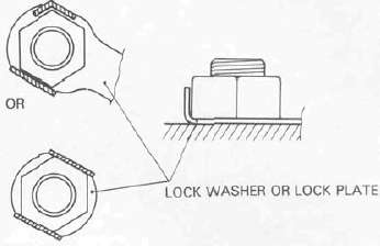
Cotter pins should be replaced after one use.
Upper Crankcase Assembly
Upper Crankcase AssemblyCRANKSHAFT/PISTON
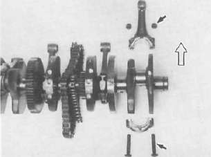
. WHEN INSTALLING THE CONNECTING ROD. BE SURE THAT THE SECURING NUTS ARE ON TOP.
Engine assembly
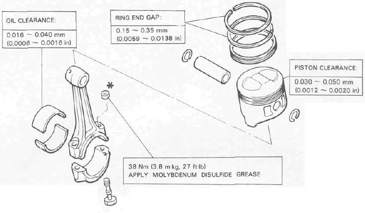
1. Upper crankcase a. Install the connecting rods onto the crankshaft with the proper connecting rod bearings and apply molybedenum disulfide grease to the bolt threads. Apply torque evenly to both ends of the cap.
CAUTION: While tightening, if a torque of 38 Nm (3.8 mkg, 27 ft-lb) or more is reached, DO NOT STOP tightening until final torque is reached.
If tightening is interrupted between 35 Nm (3.5 mkg, 25 ft-lb) and 41 Nm (4.1 mkg, 30 ft-lb), loosen the nut to less than 30 Nm (3.0 mkg, 22 ft-lb) and start again. Tighten to full torque specification without pausing.
CAUTION: When installing the connecting rod, be sure that the securing nuts are on top. Otherwise, engine damage will result.
Rod cap torque: 38 Nm (3.8 mkg, 27 ft-lb)
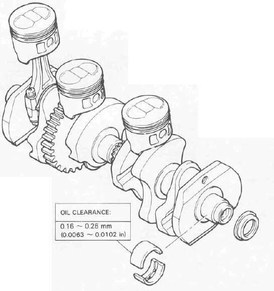
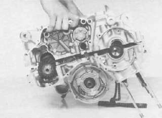
b. Install the proper crankshaft main bearings into the crankcase and place the crankshaft. Oil the bearings liberaly.
NOTE: Do not forget to install the crankshaft oil seal (L.H.), blind plug (R.H.), "HY-VO" chain and cam chain on the crankshaft before installing. Also, install the chain guide into upper crankcase if removed.
c. Install the starter idle gear, shaft, stopper plate, and new lock plate. Tighten the bolt securely and bend the lock tabs along the bolt flats.
Tightening torque:
10 Nm (1.0 mkg, 7.2 ft-lb)
1, Lock washer
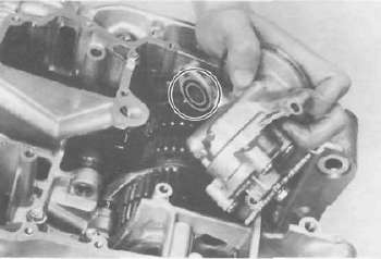
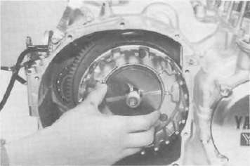
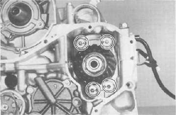
d. Put the starter clutch and sprocket assembly in the "HY-VO" chain and lay it into the crankcase.
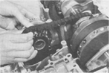
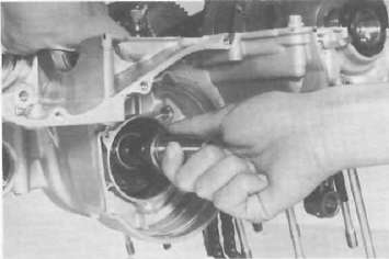
e. Install the A.C.G. Generator shaft into the starter clutch assembly.
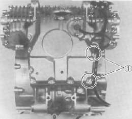
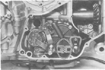
f. Install the "HY-VO" chain oil spray nozzle. The locating pin on the nozzle should be placed into the crankcase locating slot. Do not forget to install the new "O-ring" onto the nozzle.
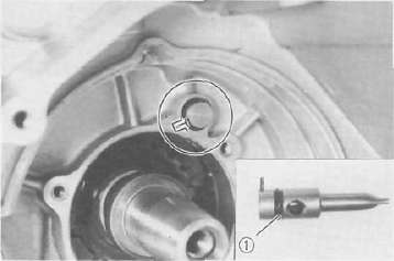
1. O-ring
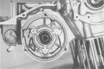
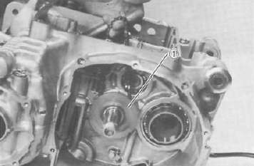
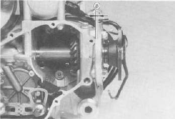
g. Install the new "O-ring" onto the bearing housing and install it with the panhead screw.
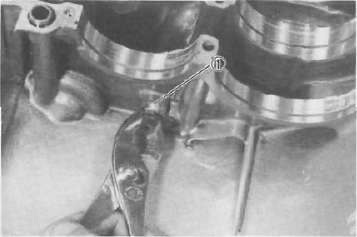
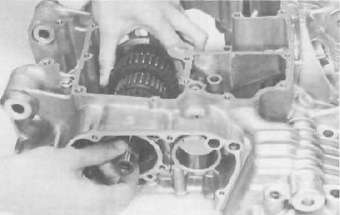
h. Install the transmission main axle assembly on the upper crankcase. Point the bearing locating pin toward the crankshaft and lay it on the case.
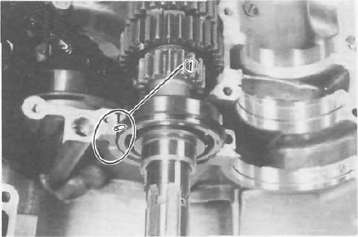
1. Bearing locating pin
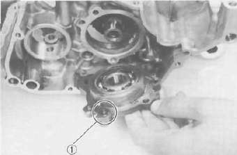
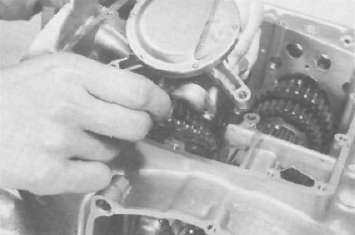
i. Install the middle driven gear (without the middle drive pinion gear).
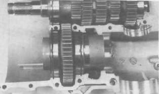
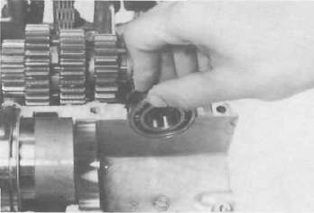
j. Install the middle driven gear shaft end bearing.
k. Install the dowel pin with "O-ring" into the crankcase.
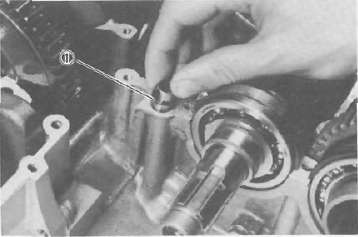
1. O-ring
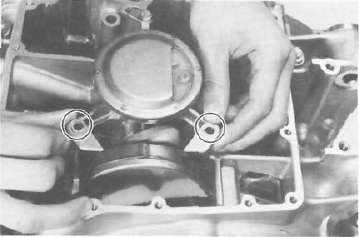
2. Lower crankcase a. Install the transmission drive axle assembly into the crankcase.
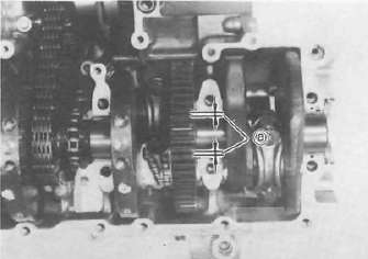
b. Install the 5th wheel gear and bearing onto the drive axle. Install the bearing cover. Be sure the "O-ring" is on the cover.
1. O-ring
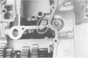
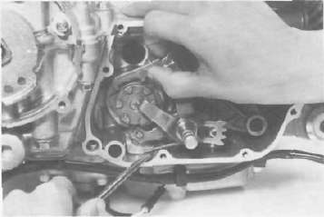
c. Install the shift cam and secure it with the guide pin. Install the stopper plate and bolt and tighten securely.
d. Install the neutral switch.
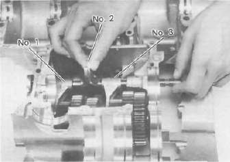
e. Install the shift forks and guide bar. Each shift fork is identified by a number cast on its side. All the numbers should face the left side and numbered 1, 2, and 3 from left.
Transmission, Clutch and Middle gear
Transmission, Clutch and Middle gearTRANSMISSION
3. Crankcase assembly a. Apply Yamaha bond #4 sealant or equivalent to the crankcase mating surface. Be very careful not to allow any sealant to come in contact with the oil gallery "O-ring" and crankshaft bearings. It is extremely important, however, that sealant be applied around the case stud holes. Apply sealant to within 2 — 3 mm (0.08 — 0.12 in) of the bearings.
CAUTION: Failure to apply sealant here will result in reduced oil pressure and possible crank seizure.
a. 2 — 3 mm (0.08 — 0.12 in) Do not apply sealant
b. The crankcases are assembled by placing the upper case half on the bench and lowering the lower case onto it.
NOTE: Be sure that shift fork No. 2 engages the groove in the 2nd pinion gear on the main axle.
CAUTION: Before installing and torquing the crankcase bolts, check to make sure the transmission is functioning properly by shifting it by hand with the shift cam.
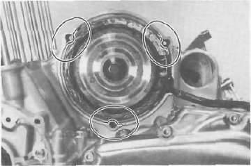
c. Start installation of the crankcase bolts with the center crankshaft area bolts. Place the two bolts without washers in the oil filter area.
d. The crankcase bolts should be torqued in proper sequence. Refer to the tightening sequence in the illustration.
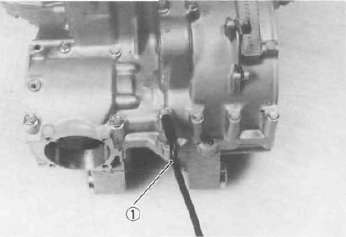
1. Engine ground wire
CRANKCASE TIGHTENING SEQUENCE LOWER CASE
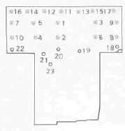
UPPER CASE
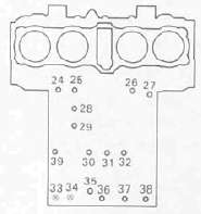
8 mm bolt: 24 Nm (2.4 m kg. 1 7 ft lb) 6 mm bolt: 12 Nm (1.2 m kg. 8 7 ft-lb)
4. Oil pump and strainer cover
a. Place the oil pump drive chain on the transmission main axle.
b. Install the thrust plate onto the transmission main axle.
c. Install the oil pump drive sprocket onto the main axle without the spacer collar and place the oil pump drive chain on its sprocket.
1. Oil pump drive sprocket
d. Place the drive chain on the oil pump driven sprocket and install the pump on the crankase. The "O-ring" should be installe properly.
e. Install the drive chain cover on the oil pump and secure with the 2 shouldered bolts and one normal 6 mm bolt.
Tlightening torque:
12 Nm (1.2 mkg, 8.7 ft-lb)
f. Install the strainer cover and torque the bolts to the specification.
Tightening torque:
7 Nm (0.7 m-kg, 5.1 ft lb)
1 Wire clamps
CLUTCH
5. Clutch assembly
a. Insert the spacer coller into the oil pump drive sprocket.
b. Install the primary driven gear (clutch housing) without the bearing and inner spacer.
CAUTION: Be sure that the oil pump drive gear tabs engage the clutch housing grooves on it's back or the tabs will be damaged when tightening the clutch boss securing nut.
1. Spacer collar
c. Install the primary driven gear bearing and inner spacer into the clutch housing.
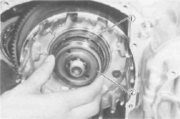
1 Driven gear bearing 2. Inner spacer
d. Install the large thrust plate and clutch boss onto the main axle.
e. Install a new lock washer-and nut and tighten the nut to the specified torque. Use the clutch boss holder (special tool).
Tightening torque:
70 Nm (7.0 nrvkg, 50 ft-lb)
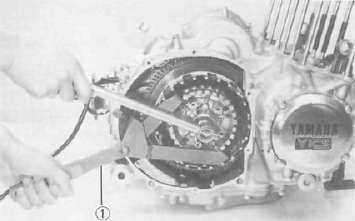
1. Clutch boss holder
f. Bend the lock washer tabs along the nut flats.
1. Lock tab
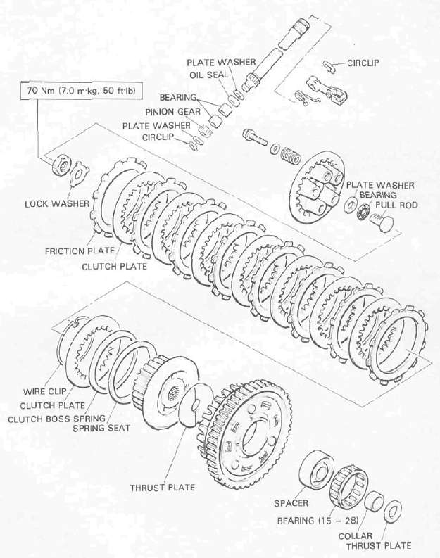
g. Install the clutch plates and friction plates alternately on the clutch boss, starting with a friction plate and ending with a friction plate.
h. Install the plate washer, thrust bearing, and clutch pull rod into the clutch pressure plate from inside.
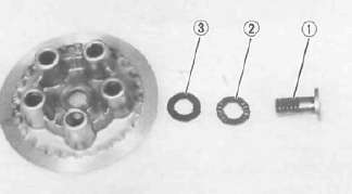
1. Pull rod 2. Thrust bearing 3. Plate washer
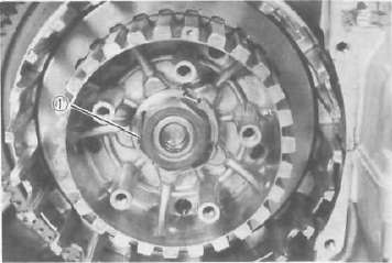
i. Install the pressure plate assembly onto the clutch boss.
NOTE: Pressure plate has a dot on it which must line up with the dot on clutch boss.
j. Install the clutch springs and screws. Tighten the screws.
Clutch screw torque: 8 Nm (0.8 m-kg, 5.8 ft lb)
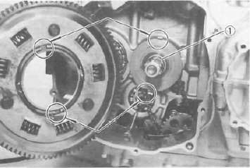
k. Install the oil collector plate.
1. Oil collector plate
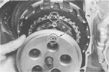
I. Set the gear of the clutch pull rod on the pressure plate facing approximately 45° from horizontal toward the rear; set the clutch lever (if installed) on the right crankcase cover parallel to the gasket surface and install the cover to the crankcase. Do not forget to install two dowel pins.
m. If the clutch lever has been removed, install the lever return spring and lever on the shaft after installing the right crankcase cover. In this case make sure that the punch mark on the lever should align with the mark on the crankcase cover when pushing the lever towards the front by hand and then install the circlip.
1 Push
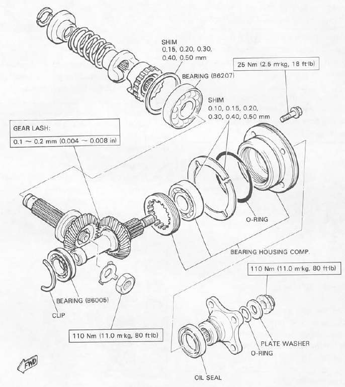
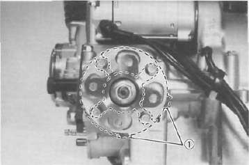
6. Middle gear (installation only, refer to page for the middle gear adjustment). a. Install the middle drive gear assembly with the proper size of shim(s) and secure it with the bearing retainers and new "TORX" screws.
Tightening torque: 25 Nm (2.5 mkg, 18 ft-lb)
b. Stake the screw heads to the dents on the bearing retainers with a center punch.
c. Install the driven gear assembly with the proper size of shims and secure it with the bolts. Apply a thread locking compound such as "LOCTITE" to the bolt threads.
Tightening torque:
25 Nm (2.5 mkg, 18 ft-lb)
1 Shims
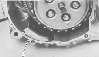
d. Install the middle gear case half moon seal onto the crankcase.
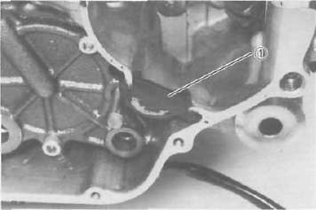
1. Seal
Shifter, Generator, Starter and Pickup coils
Shifter, Generator, Starter and Pickup coils7, Shifter assembly a. Install the shift shaft assembly with the stopper lever.
b. Install the shift lever assembly with the positioning spring is properly located on the stopper pin and the teeth should be set properly as shown.
c. Install the left crankcase cover (shifter cover) using a new gasket.
Tightening torque:
12Nm(1.2 mkg, 8.7 ft-lb)
8. A.C. generator a. Install the rotor onto the shaft and tighten the bolt using the rotor holding tool (special tool).
Tightening torque:
55 Nm (5.5 mkg, 40 ft-lb)
b. Install the stator coil assembly onto the crankcase and align the grooves on the stator core with the bolt holes on the crankcase.
c. Install the A.C. generator cover assembly and tighten the bolts to the specification. Do not forget to install the new gasket.
Tightening torque:
12 Nm (1.2 mkg, 8.7 ft-lb)
9. Starter motor
a. Route the A.C. generator leads as shown.
b. Install the starter motor and tighten the bolts to the specification.
Tightening torque: 7 Nm (0.7 mkg, 5.1 ft-lb)
NOTE: Be careful the "O-ring" is not damaged when installing the starter motor.
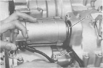
1 O-ring 2. A. C generator lead
10. Pick-up coil assembly
a. Install the pick-up coil assembly onto the crankcase.
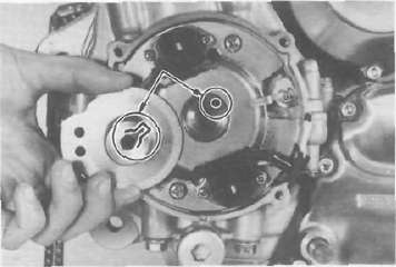
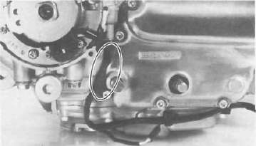
b. Install the timing plate on the crankshaft and tighten the bolt to the specification.
NOTE:
1) Note that there is the locating pin on the crankshaft and the corresponding slot in the timing plate which must be aligned to install the timing plate.
2) Make sure the wire harness clips are properly positioned.
Pistons, Cylinder and Head
Pistons, Cylinder and Head11. Pistons and cylinder
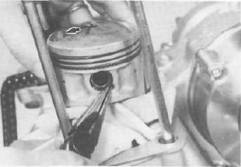
a. Install the pistons on the rods. The arrow on the piston must point to the front of the engine.
NOTE: Before installing the piston pin clips, cover the crankcase with a clean rag so you will not accidentally drop the circlip into the crank-case. Always install new piston pin circlips.
b. Install the rear chain guide on its pivot. Tighten the holding bolt until it stops and then loosen 1/4 turn and then tighten the lock nut
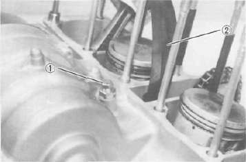
1. Holding bolt 2. Rear cran guide
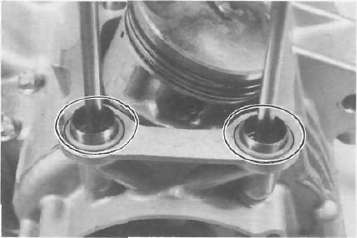
c. Install the new cylinder base gasket and dowel pins. Install the new "O-rings" to the right side dowel pins.
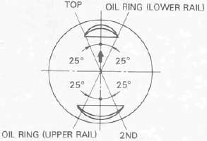
d. Set the crankshaft so that the all pistons are equal height and align the piston rings as shown.
CAUTION: Make sure the ends of the oil ring expanders are not overlapped.
NOTE: Manufacture's marks or numbers stamped on the rings are en the top side of the rings. Coat the pistons and rings well with oil.
e. Install the piston ring compressors (special tool) and piston bases (special tool). Four piston bases are required.
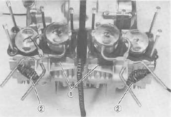
1. Piston bases 2. Piston ring compressors
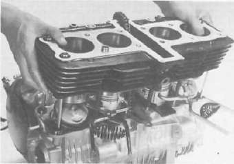
f. Tie the cam chain with a piece of mechanic's wire and feed it through the chain opening. Carefully lower the cylinder onto the pistons. Remove the ring compressors and piston bases and repeat this procedure for pistons 1 and 4.
g. Install the cylinder securing nut (front side) and tighten it to the specification.
Tightening torque:
20 Nm (2.0 mkg, 14 ft lb)
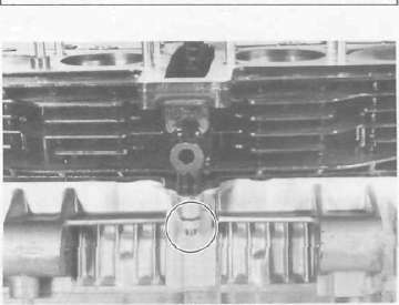
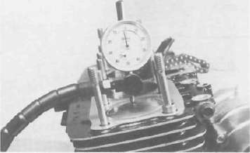
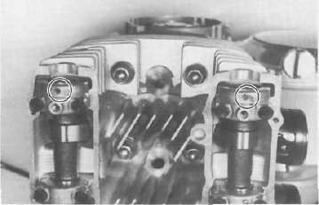
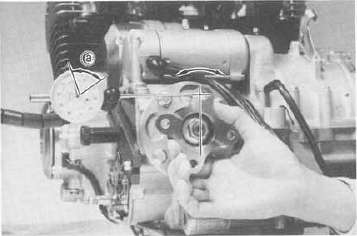
h. Set the dial gauge on the No. 1 piston head center as shown to find the No. 1 piston top dead center and check whether the "T" mark on the timing plate and stationary pointer are aligned or not. If not, loosen the pointer securing screw and adjust.
CYLINDER HEAD
12. Cylinder head and cam shafts a. Install the new cylinder head gasket. Install the dowel pins and "O-rings". Locate the cam chain cavity cylinder seal with the tabs down.
b. Install the cylinder head onto the cylinder. Pull the cam chain through the cylinder head as it is installed. Tie the cam chain so that it does not fall into the crankcase.
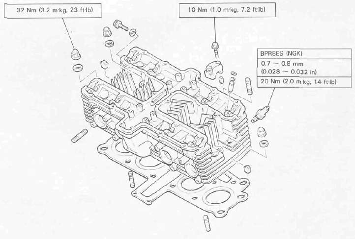
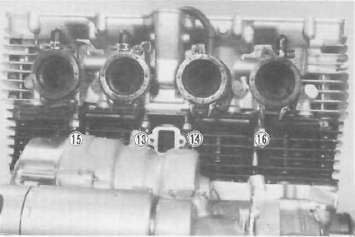
c. Place the upper cylinder head nuts and washers in place. Follow the illustration for the proper tightening sequence. Torque all nuts in two stages and final torque the upper nuts to the specification.
Tightening torque:
32 Nm (3.2 mkg, 23 ft lb)
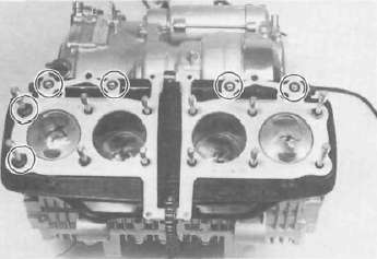
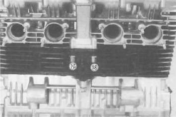
NOTE: Don't forget the lower nuts on the front and rear of the cylinder head. Torque to the specification.
Tightening torque: 20 Nm (2.0 mkg, 14ft-lb)
NOTE: Tighten the nuts in two stages, 1/2 torque value and then full torque value. Also lubricate the bolt threads with the engine oil to achieve proper torque values.
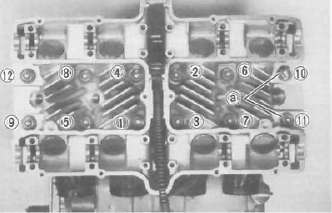
a. Copper washers
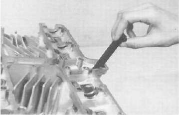
d. Install the front cam chain guide being certain that it is in its holder down below.
e. Rotate the crankshaft counterclockwise direction until the crankcase pointer and "T" mark on the timing plate are aligned.
f. With the cylinders No. 1 and 4 at the top dead center, slip the cam chain over the sprocket.
cj. Lubricate all cam caps and cam bearings surfaces liberally with oil.
h. Place the cam caps in their proper positions. Install the bolts only finger tight.
CAUTION: The cam caps must be tightened evenly or damage to the cylinder head, cam caps and cam will result. The spaces between the caps and cylinder head should be equal.
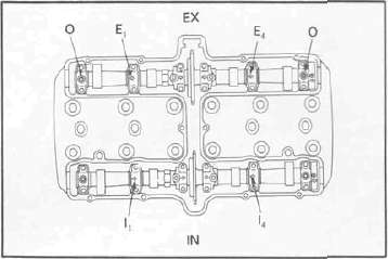
i. Torque the cam cap bolts in two stages and final torque to the specification.
Tightening torque:
10 Nm (1.0 m-kg, 7.2 ft-lb)
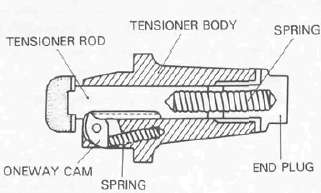
CAM CHAIN
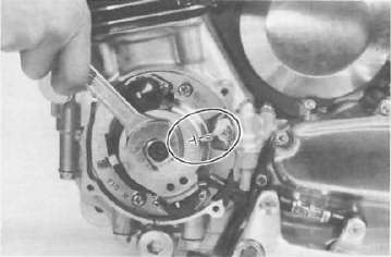
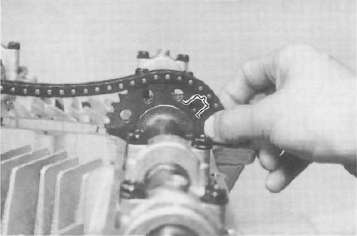
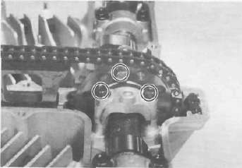
13. Cam chain, cam sprockets and chain tensioner a. Rotate each cam shaft until the dot on the cam is aligned with the hole on the right cam cap.
CAUTION: Use extreme caution when rotating the cams. Two possible dangers exist. First, the wrench may contact the head and fracture it. Or second, a valve may become bent if the cam is turned the wrong way.
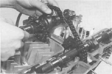
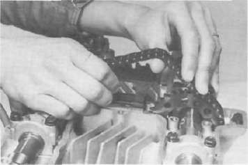
b. Carefully lift the cam chain from the exhaust cam sprocket and pull upward to remove any slack in the chain between the crankshaft and the exhaust cam sprocket. With all slack removed, place the chain back on the cam sprocket.
c. Grip each sprocket simultaneously and place them on the camshaft shoulders while continuing to keep tension on the chain from the crankshaft to the exhaust sprocket
CAUTION: Use only the special hardened shouldered bolts to install the cam chain sprockets to the cams.
Make sure the rollers of the cam chain are centered on both chain guides.
d. Rotate the sprockets slightly to align the bolt holes and insert one special bolt in each sprocket.
NOTE: Tighten only finger tight at this time.
e. Install the center chain guide.
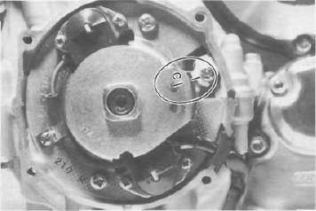
f. Rotate the crankshaft counterclockwise and align the "C" mark on the timing plate with the timing pointer.
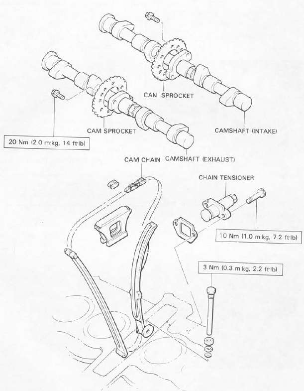
g. Remove the end plug and spring from the tensioner assembly.
h. Unlock the oneway cam by pushing it with your finger and push the tensioner rod into the tensioner body until it stops.
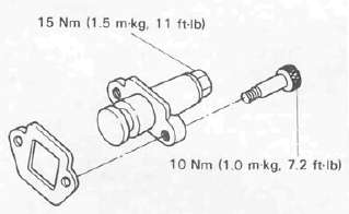
i. Install the tensioner to the cylinder and torque the bolts to the specification.
Tightening torque:
10 Nm (1.0 m-kg, 7.2 ft-lb)
j. Reinstall the spring and end plug with the gasket. Torque the end plug to the specification.
Tightening torque:
15 Nm (1.5 m-kg, 11 ft-lb)
k. Rotate the crankshaft more than one full revolution and align the "T" mark on the timing plate with the timing pointer. With the crankshaft at the "T" mark, the dots on the cams should be aligned with the raised holes on the right cam caps. If they are not aligned, disassemble the sprockets and chain tensioner and repeat above procedures.
I. Rotate the crankshaft and install the two remaining shoulder bolts into the cam sprockets. Torque all four sprocket holding bolts to the specification.
CAUTION: Be sure to attain the specified torque value to avoid the possibility of these bolts coming loose and causing serious damage to the engine.
Tightening torque:
20 Nm (2.0 m-kg, 14 ft-lb)
m. Adjust all valves as described in the "PERIODIC INSPECTIONS AND ADJUSTMENTS".
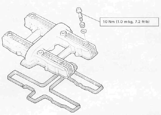
n. Install the cylinder head cover with a new gasket.
o. Install the left and right crankcase covers. The left crankcase cover (pickup coil cover) is required a gasket.
Middle gear servicing
1. Disassembly
Refer to page 3-13 for disassembly.
2. Inspection
Refer to page 3-29 for inspection.
3. Gear lash check
NOTE: The middle gear lash can be checked only when the gears are installed in the crankcase.
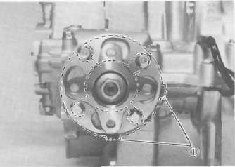
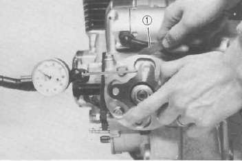
a. Install the middle drive pinion holder (special tool) on the crankcase to hold the drive gear stationary during the lash measurement.
NOTE: Before installing the tool, loosen the holder bolt all the way out and after installation tighten this bolt as tight as necessary (finger tight is generally sufficient).
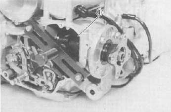
1. Middle drive pinion holder
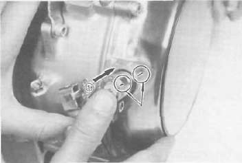
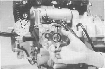
b. Set the dial gauge to the middle drive flange as shown and gently rotate the drive flange back and forth. Note the lash measurement on the dial gauge.
Middle gear lash: 0.1 ~~ 0.2 mm (0.004 - 0.008 in)
a Middle gear lash
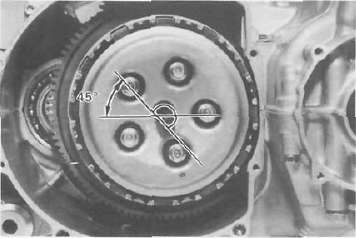
c. Check this engagement at 4 positions. Rotate the drive flange 90° each time and repeat the gear lash check.
NOTE: If the gear lash exceeds the specified limit and adjustment is necessary, the engine or swing arm should be removed from the motorcycle.
4. Gear lash adjustment a. Install the driven gear housing assembly into the crankcase leaving about a 2 mm (0.08 in) gap between the housing and crankcase and install the two bolts to the bearing housing 180° opposite to each other.
a. 2 mm (0.080 in)
b. Install the middle drive shaft holder and dial gauge (refer to "Middle gear lash check").
c. Slowly tighten the bolts alternately until the dial gauge lash measurement reaches 0.2 mm (0.008 in).
Middle Gear
Middle GearMIDDLE GEAR/DAMPER
a. Middle gear lash 0 2 mm (0.008 in)
d. Measure the gap between the driven gear bearing housing flange and the crankcase with a feeler gauge. This is the shim size required.
1 Feeler gauge
e. Install the proper sized shims as shown and tighten the driven gear housing to the specified torque. Recheck the gear lash, it should be within the specification, if not readjust the shims.
Gear lash: 0.1 — 0.2 mm
(0.004 — 0.008 in)
1. Shims
5. Drive gear positioning NOTE:
When the following part(s) is replaced with new one(s), drive gear positioning is necessary:
a. Crankcase
b. Middle gears
c. Middle gear bearing housing
a. The shim thickness necessary for the drive gear positioning can be calculated from the infomations found on the upper crankcase and on the drive gear end.
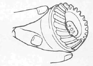
b. To fined shim thickness "A" use the formula:
A = c - a - b
Where:
a = a numeral (usually a decimal number) printed on the shaft end as shown above and either added to or detracted from the nominal size "43".
b = a bearing thickness (considered constant)
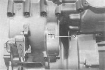
c = a numeral (usually a decimal number) found on the upper crankcase half near the main bearing selection numbers and added to the nominal size "60".
Distance "b" = 16.94 mm
Example:
1) If the shaft is marked +03....."a"
is 43.03 mm.
2) "b" is 16.94 mm.
3) If the crankcase is stamped "45" ....."c" is 60.45 mm.
A = c - a - b
A = 60.45 - 16.94 - 43.03
A = 0.48
Then the necessary shim thickness
is 0.48 mm. c. Shim size are supplied in the following thicknesses:
0.15 mm, 0.20 mm, 0.30 mm, 0.40 mm, and 0.50 mm.
Because the shims can only be selected in 0.05 mm increments the following chaft should be used when encountering last digits that are not 5 or zero(0):
|
Last digits |
Rounding |
|
0, 1,2 |
0 |
|
3, 4, 5, 6, 7 |
5 |
|
8,9 |
10 |
Shim 0.30 mm + 0.15 mm