Valve Clearance Check
Valve Clearance CheckNOTE:
Valve clearance must be measured with the engine and at room temperature.
1. Remove the seat and remove the fuel tank holding clip and retainer.
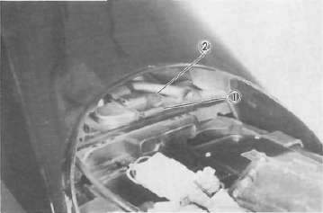
1. Clip 2. Retainer
2. Remove the starter (CHOKE) wire and spark plug leads.
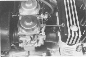
1. Starter (CHOKE) wire
3. Remove the cylinder head cover and left crankcase cover (pick-up base cover). Care should be taken to not scratch or damage the gasket sealing surfaces.
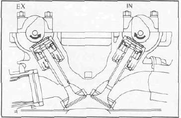
4. Turn the crankshaft with the nut on the left end of the crankshaft to turn the cams. The proper position of the cam when measuring the valve clearance is with the cam lobe directly opposite the valve lifter.
5. Insert a feeler gauge between the valve lifter and the camshaft base circle.
|
Intake valve clearance (cold): |
|
0.11 - 0.15 mm (0.0043 ~~ 0.0059 in) |
|
Exhaust valve clearance (cold): |
|
0.16 — 0.20 mm (0.0063 — 0.0079 in) |
Valve clearance adjustment
Valve clearance is adjusted by replacing the adjusting pad on the top of the valve lifter. Adjusting pads are available in 25 thicknesses ranging from No. 200 (2.00 mm) to No. 320 (3.20 mm) in steps of 0.05 mm. The thickness of each pad is marked on the pad face that contacts the valve lifter (not the cam). Adjustment of the valve clearance is accomplished as follows:
1. Determine valve clearance (feeler gauge measurement.)
2. Remove adjusting pad and note number.
3. Select proper pad from appropriate chart (intake or exhaust chart).
4. Install new pad andcheck installed clearance.
Pad selection procedure
1. Measure valve clearance. If clearance is incorrect record the measured amount of clearance. This must be measured carefully.
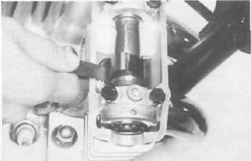
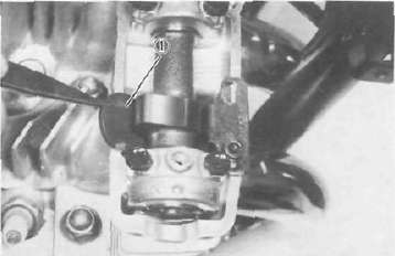
2. There is a slot in the valve lifter. This slot must be positioned opposite the blade of the tappet adjusting tool before the tools is installed.
3. Turn the cam until the lobe fully depresses the valve lifter and opens the valve. Install the tappet adjusting tool as shown to hold the lifter in this depressed position.
NOTE:
The tappet adjusting tool is fastened to the cylinder head securely using an alien screw. Make sure that the tool contacts the lifter only, and not the pad.
CAUTION:
If the cam lobe touches the tappet adjusting tool, the stress may fracture the cylinder head. DO NOT ALLOW THE CAM LOBE TO CONTACT THE TAPPET ADJUSTING TOOL.
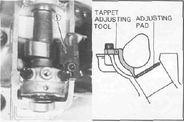
1. Tappet adjusting tool
4. Carefully rotate the cam so that the pad can be removed. To avoid cam touching the adjusting tool, turn cams as follows: (view from left side of the motorcycle)
Intake: Carefully rotate CLOCKWISE. Exhaust: Carefully rotate COUNTERCLOCKWISE.
5. Remove the pad from the lifter. There is a slot in the lifter. Use a small screwdriver or other blade and tweezers or a magnetic rod to remove the pad. Note the number on the pad.
1 Adjusting pad
6 Proper pad selection is made as follows:
Chart lookup method:
Refer to the appropriate chart for exhaust or intake valves:
0.11 to 0.15mm required clearance (Intake side) chart
0.15 to 0.20mm required clearance (Exhaust side) chart
a. Find number of original (installed) pad number on chart. Read down on chart.
b. Find measured valve clearance (from step 1) on chart. Read across.
c. At the intersection of installed pad number (down) and measured clearance (across) is a new pad number.
EXAMPLE:
Intake valve, installed pad: No. 250 (read down)
Measured clearance:0.32 mm (read across)
New pad number: No. 270(intersection of down & across)
Alternate shim calculation method:
Since all shims come in .05mm (.002") increments, you can quickly calculate the required size without a chart.
If the measured clearance is within 0.05mm (0.002") of the required clearance, then no change is needed.
If the measured clearance greater than 0.05mm (0.002") but 0.10mm (0.004") or less different than the required clearance then the next size shim is required.
If the measured clearance greater than 0.10mm (0.004") but 0.15mm (0.006") or less different than the required clearance then the next size shim is required.
Clearances that are too small require thinner shims. Clearances that are too large require thicker shims.
Example: Required exhaust valve clearance is 0.16~0.20mm. Measured clearance is 0.12mm (gap too small). Installed shim is Y270. Required shim is one size thinner: Y265.
NOTE:
The new pad number is to be used as a guide only. Verify the correctness of this choice in the following step(s).
7. Install the new pad in the lifter. Install the pad with the number down.
8. Remove tappet adjusting tool.
9. Turn crankshaft to rotate cam several rotations. This will set the pad in the lifter.
10. Check valve clearance (step 3). If clearance is incorrect, repeat preceding steps until proper clearance is obtained.
11. Inspect head cover gasket. If bent or torn, replace gasket.
12. Reinstall removed parts in reverse order.