XJ650J/K (Maxim) Service Manual
XJ650J/K (Maxim) Service ManualTABLE OF CONTENTS:
Chapter 1, Introduction
Chapter 1, Introduction
YAMAHA
XJ650J/K
Service Manual
Note:
A separate manual covers the European and Australian versions of this model.
NOTICE
This manual was written by the XJ Owners Group
to replace the composite set of manuals and supplements offered by
Yamaha Motor Company primarily for use by Yamaha dealers and their
qualified mechanics.This is a complete manual, not a supplement.
It is not possible to put an entire mechanic's
education into one manual, so it is assumed that persons using this
book to perform maintenance and repairs have a basic understanding of
the mechanical concepts and procedures inherent to motorcycle repair
technology. Without such knowledge, attempted repairs or service to
this model may render it unfit to use and/or unsafe.
Particularly important information is distinguished in this manual by the following notations.
NOTE:
A NOTE provides key information to make procedures easier or clearer.
CAUTION:
A CAUTION indicates special procedures that must be followed to avoid damage to the motorcycle.
WARNING:
A
WARNING indicates special procedures that must be followed to avoid
injury to a motorcycle operator or person inspecting or repairing the
motorcycle.
Starting Serial Number
|
XJ650J |
5N8-000101 |
FOREWORD
NOTICE
This model has been designed and manufactured to perform within certain specifications in regard to performance and emissions. Proper service with the correct tools is necessary to ensure that the motorcycle will operate as designed. If threre is any question about a service procedure, it is imperative that you contact a Yamaha dealer for any service information changes that apply to this model. This policy is intended to provide the customer with the most satisfaction from his motorcycle and to conform with federal environmental quality objectives.
CHAPTER 1. GENERAL INFORMATION
MOTORCYCLE IDENTIFICATION
A. Frame Serial Number
The frame serial number is stamped into the right side of the steering head pipe.
B. Engine Serial Number
The engine serial number is stamped into the elevated part of the right rear section of the engine.
NOTE:
The first three digits of these numbers are for model identifications; the remaining digits are the unit production number.
SPECIAL TOOLS
The proper special tools are necessary for complete and accurate tune-up and assembly. Using the correct special tool will help to prevent damage from improper tools or improvised techniques.
A. For Tune-up
1. Compression gauge
2. Timing light
3. Tachometer
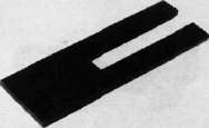
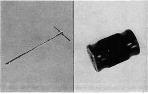
4. Tappet adjusting tool P/N. 90890-01245-00
This tool is necessary to replace valve adjusting pads. This can also be used for the XS750, XS850 and XS1100.
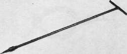
5. Vacuum gauge
P/N. TLU-11080-30-02
This gauge is needed for carburetor synchronization.
B. For Engine Service
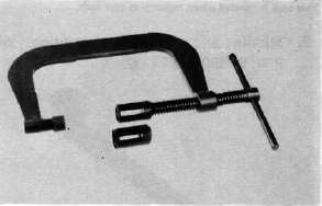
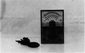
1. Clutch hub holder P/N. TLM-90910-42-00
This tool is used to hold the clutch when removing or installing the clutch boss lock nut.
Valve guide reamer P/N. 90890-01227-00
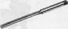
This must be used when replacing the valve
guide
3. Valve seat cutter
P/N.TLM-90910-43-20
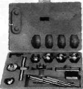
This tool is needed to re-surface the valve seat.
2.
4. Valve guide remover P/N. 90890-01225-00
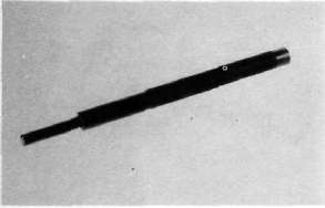
This must be used to remove the valve guides,
5. Valve guide installer P/N. 90890-04017-00
This tool is needed for proper installation of the valve guides.
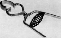
6. Valve spring compressor P/N. 90890-01253-00
This tool must be used for removing and installing the valve assemblies.
7. Piston ring compressor P/N. 90890-04044-00
This is used to compress piston rings when installing the cylinder.
8. Piston base
P/N. 90890-01067-00
Use 4 of these to hold the pistons during cylinder installation.
9. Rotor puller
P/N. 90890-01080-00
This tool is needed to remove the A.C. Generator rotor.
10. Rotor puller attachment P/N. 90890-04052-00
This tool is needed when removing the A.C. Generator rotor together with the rotor puller.
11. Rotor holding tool P/N. 90890-04043-00
This tool is used to hold the A.C. Generator rotor during removal and installation.
12. Dial gauge stand
P/N. 90890-01258-00
This tool is needed to hold the dial gauge.
13. Dial gauge
P/N. 90890-03097-00
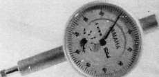
This dial gauge is used to determine piston position for correct timing.
C. For Shaft Drive Service
1. Middle drive pinion holder P/N. 90890-04051-00
This tool is needed when measuring gear lash.
2. Middle and final gear holding tool P/N. 90890-01229-00
This tool is needed when measuring gear lash.
3. Gear lash measurement tool (Final gear) P/N. 90890-01230-00
This tool is needed when measuring gear lash for final gear.
4. Final gear holding tool P/N. 90890-01254-00
This tool is needed when measuring gear lash.
5. Damper compressor P/N. 90890-04011-00
This tool is needed to disassemble and reassemble the middle gear damper.
6. Middle drive shaft nut wrench P/N. 90890-04045-00
This tool is used to loosen and tighten the drive shaft nut,
7. Middle drive shaft holder P/N. 90890-04046-00
This tool is needed when loosening and tightening the drive shaft nut.
8. Drive pinion bearing retainer remover P/N. 90890-04050-00
This tool is used to loosen and tighten the final gear drive pinion bearing retainer.
9. Armature shock puller (M10 x 1.25) P/N. 90890-01290-00, 90890-01291-00

These tools are used to remove the final gear drive pinion.
10. Crank installer adapter (M10x1.25/M14x1.5) P/N. 90890-01277-00
This adapter is needed when using the armature shock puller.
11. Drive shaft puller P/N. 90890-04012-00
This tool is used to remove the drive shaft.
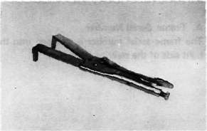
12. Slide hammer
P/N. 90890-01083-00, 90890-01084-00
These tools are used to remove the drive shaft.
13. Front fork cylinder comp. holder P/N. 90890-01300-00
This tool is used to loosen and tighten the front fork cylinder comp. holding bolt.
D. For Electrical Components
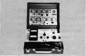
The uses of these tools are described in CHAPTER 6. 1. Pocket tester
P/N. 90890-03104-00
2. Electro tester
P/N. 90890-03021-00
Chapter 2, PERIODIC MAINTENANCE
Chapter 2, PERIODIC MAINTENANCECHAPTER 2. PERIODIC INSPECTIONS AND ADJUSTMENTS
INTRODUCTION
This chapter includes all information necessary to perform recommend inspection
and adjustments. These preventative maintenance procedures, if followed, will
insure more reliable vehicle operation and a longer service life. The need for costly
overhaul work will be greatly reduced. This information applies not only to vehicles
already in service, but also to new vehicles that are being prepared for sale. Any
service technician performing preparation work should be familiar with this entire chapter.
MAINTENANCE INTERVALS CHARTS
MAINTENANCE INTERVALS CHARTSProper periodic maintenance is important. Especially important are the maintenance services
related to emissions control. These controls not only function to ensure cleaner air but
are also vital to proper engine operation and maximum performance. In the following tables
of periodic maintenance, the services related to emissions control are grouped separately.
Periodic maintenance emission control system
|
No. |
Item |
Remarks |
Initial break-in |
Thereafter every |
||
|
1,000 km (600 mi) or 1 month |
5,000 km (3,000 mi) or 7 months |
4,000 km (2,500 mi) or 6 months |
8,000 km (5,000 mi) or 12 months |
|||
|
1* |
Valve clearance |
Check and adjust valve clearance when engine is cold. |
O |
O |
||
|
2 |
Spark plugs |
Check condition. Adjust cap. Clean. Replace at 13,000 km (or 18 months) and thereafter every 12,000 km (or 18 months) |
o |
o |
Replace every 12,000 km (7,500 mi) or 18 months |
|
|
3* |
Crankcase ventilation system |
Check ventilation hose for cracks or damage. Replace if necessary. |
o |
o |
||
|
4* |
Fuel line |
Check fuel hose and vacuum pipe for damage. Replace if necessary. |
o |
o |
||
|
5* |
Exhaust system |
Check for leakage. Retighten if necessary. Replace gasket(s) if necessary. |
o |
o |
||
|
6* |
Idle speed |
Check and adjust engine idle speed. Adjust cable free play if necessary. |
o |
o |
||
|
7* |
Carburetor synchronization |
Adjust synchronization of carburetors. |
o |
o |
||
*It is recommended by Yamaha that these items be serviced by a Yamaha dealer or other qualified mechanic.
General maintenance/lubrication
|
No. |
Item |
Remarks |
Type |
Initial break-in |
Thereafter every |
|||
|
1,000 km (600 mi) or 1 month |
5,000 km (3,000 mi) or 7 months |
4,000 km (2,500 mi) or 6 months |
8,000 km (5,000 mi) or 12 months |
16,000 km (10,000 mi) or 24 months |
||||
|
1 |
Engine oil |
Warm-up engine before draining. |
Refer to NOTE 1 |
O |
O |
O |
||
|
2 |
Oil filter |
Replace. |
- |
o |
0 |
O |
||
|
3 |
Final gear oil |
Replace. |
Refer to NOTE 2 |
0 |
O |
|||
|
4* |
Air filter |
Clean wilh compressed air. |
Refer to NOTE 3 |
0 |
O |
|||
|
5* |
Brake system |
Adjust free play. Replace pads if necessary. (Front) Replace shoes if necessary (rear). |
- |
o |
0 |
O |
||
|
6* |
Clutch |
Adjust free play. |
- |
o |
o |
o |
||
|
7* |
Control and meter cable |
Apply chain lube thoroughly. |
Yamaha chain and cable lube or SAE 10W/30 motor oil |
o |
o |
o |
||
|
8* |
Rear arm Pivot bearing |
Check bearings assembly for looseness. Moderately repack every 16,000 km (10,000 mi). |
Medium weight wheel bearing grease |
Repack |
||||
|
9* |
A.C. Generator |
Replace generator brushes. Replace at initial 13,000 km (8,000 mi) and thereafter every 16,000 km (10,000 mi). |
- |
Replace |
||||
|
10 |
Brake/Clutch lever pivot shaft |
Apply chain lube lightly. |
Yamaha chain and cable lube or SAE 10W/30 motor oil |
O |
O |
|||
|
11 |
Brake pedal and change pedal shaft pivots |
Apply chain lube lightly. |
Yamaha chain and cable lube or SAE 10W/30 motor oil |
O |
O |
|||
|
12 |
Center and side stand pivots |
Apply chain lube lightly. |
Yamaha chain and cable lube or SAE 10W/30 motor oil |
0 |
o |
|||
|
13 |
Front fork oil |
Drain completely. Refill to specification. |
Yamaha fork oil 10Wt or equivalent |
O |
||||
|
14 |
Steering bearing and races |
Check bearings assembly for looseness. Moderately repack every 16,000 km (10,000 mi). |
Medium weight wheel bearing grease |
0 |
o |
Repack |
||
|
15 |
Wheel bearings |
Check bearings for smooth rotation. Replace if necessary. |
- |
0 |
o |
|||
|
16 |
Battery |
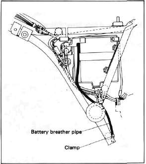
Check specific gravity Check breather pipe for proper operation. |
- ■ |
0 |
o |
|||
*Yamaha recommends that these items be serviced by your Yamaha dealer or other qualified mechanic.
Engine Maintenance
Engine MaintenanceENGINE
A. Valve Clearance Adjustment
NOTE:
Valve clearance must be measured with the engine and at room temperature.
1. Remove the seat and fuel tank.
2. Remove the horn, flasher relay, and spark plug lead wires.
3. Remove the cylinder head cover and left crankcase cover (pick-up base cover). Care should be taken to not scratch or damage the gasket sealing surfaces,
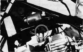
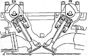
4. Turn the crankshaft with the nut on the left end of the crankshaft to turn the cams. The proper position of the cam when measuring the valve clearance is with the cam lobe directly opposite the valve lifter.
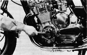
5. Insert a feeler gauge between the valve lifter and the camshaft base circle.
|
Intake valve clearance (cold): |
|
||
|
0.11- |
0.15 mm |
(0.004 ~ 0.006 |
in) |
|
Exhaust valve clearance (cold): |
|
||
|
0.16- |
-0.20 mm |
(0.006-0.008 |
in) |
Adjustment
Valve clearance is adjusted by replacing the adjusting pad on the top of the vale lifter. Adjusting pads are available in 25 thicknesses ranging from No. 200 (2.00 mm) to No. 320 (3.20 mm) in steps of 0.05 mm. The thickness of each pad is marked on the pad face that contacts the valve lifter (not the cam). Adjustment of the valve clearance is accomplished as follows:
1. Determine valve clearance (feeler gauge measurement.)
2. Remove adjusting pad and note number.
3. Select proper pad from appropriate chart (intake or exhaust chart).
4. Install new pad and check installed clearance.
Procedure
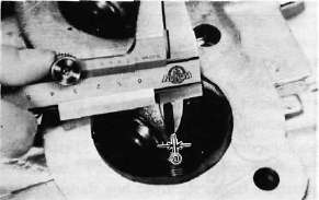
1. Measure valve clearance. If clearance is incorrect, record the measured amount of clearance. This must be measured carefully.
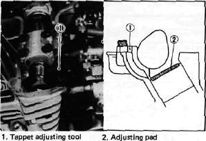
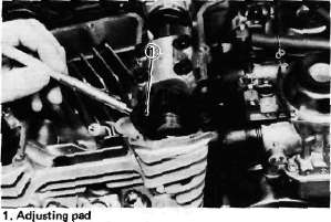
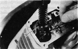
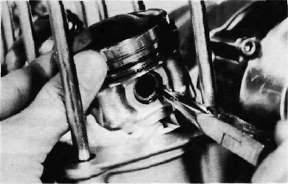
2. There is a slot in the valve lifter. This slot must be positioned opposite the blade of the tappet adjusting tool before the tools is installed.
3. Turn the cam until the lobe fully depresses the valve lifter and opens the valve. Install the tappet adjusting tool as shown to hold the lifter in this depressed position.
NOTE:
The tappet adjusting tool is fastened to the cylinder head securely using an alien screw. Make sure that the tool contacts the lifter only, and not the pad.
CAUTION:
If the cam lobe touches the tappet adjusting tool, the stress may fracture the cylinder head. DO NOT ALLOW THE CAM LOBE TO CONTACT THE TAPPET ADJUSTING TOOL.
4. Carefully rotate the cam so that the pad can be removed. To avoid cam touching the adjusting tool, turn cams as follows: (view from left side of the motorcycle) Intake: Carefully rotate CLOCKWISE. Exhaust: Carefully rotate COUNTERCLOCKWISE.
5. Remove the pad from the lifter. There is a slot in the lifter. Use a small screwdriver or other blade and tweezers or a magnetic rod to remove the pad. Note the number on the pad.
6 Proper pad selection is made as follows:
Chart lookup method:
(Use appropriate chart for exhaust or intake valves, attached to this page, below.)
a. Find number of original (installed) pad number on chart. Read down on chart.
b. Find measured valve clearance (from step 1) on chart. Read across.
c. At the intersection of installed pad number (down) and measured clearance (across) is a new pad number.
I EXAMPLE:
Intake valve, installed pad:
No. 250 (read down) Measured clearance:
0.32 mm (read across) New pad number: No. 270
(intersection of down & across)
NOTE:
The new pad number is to be used as a guide only. Verify the correctness of this choice in the following step(s).
7. Install the new pad in the lifter. Install the pad with the number down.
8. Remove tappet adjusting tool,
9. Turn crankshaft to rotate cam several rotations. This will set the pad in the lifter.
10. Check valve clearance (step 3). If clearance is incorrect, repeat preceding steps until proper clearance is obtained.
11. Inspect head cover gasket. If bent or torn, replace gasket.
12. Reinstall removed parts in reverse order.
Alternate shim calculation method:
Since all shims come in .05mm (.002") increments, you can quickly calculate the required size without a chart.
If the measured clearance is within 0.05mm (0.002") of the required clearance, then no change is needed.
If the measured clearance greater than 0.05mm (0.002") but 0.10mm (0.004") or less different than the required clearance then the next size shim is required.
If the measured clearance greater than 0.10mm (0.004") but 0.15mm (0.006") or less different than the required clearance then the next size shim is required.
Clearances that are too small require thinner shims. Clearances that are too large require thicker shims.
Example: Required exhaust valve clearance is 0.16~0.20mm. Measured clearance is 0.12mm (gap too small). Installed shim is Y270. Required shim is one size thinner: Y265.
B. Cam Chain Adjustment
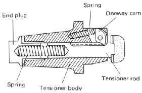
This model has been equipped the automatic cam chain tensioner. No adjustment is necessary.
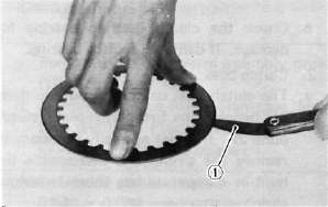
When installing this tensioner onto the cylinder proceed as follows:
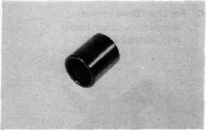
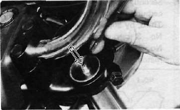
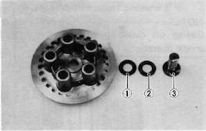
1. Remove the end plug and spring from the tensioner assembly.
2. Unlock the oneway cam by pushing it with your finger and push the tensioner rod into the tensioner body until it stops.
3. Install the tensioner to the cylinder and torque the bolts to the specification.
Tightening torque: 1.0 m-kg (7.2 ft-lb)
4. Reinstall the spring and end plug with the gasket. Torque the end plug to the specification.
Tightening torque: 1.5 m-kg (11 ft-lb)
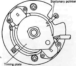
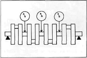
C. Ignition Timing
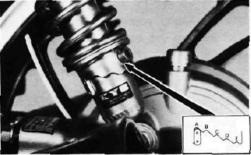
1. Ignition timing is checked with a timing light by observing the position of the stationary pointer and the marks stamped on the timing plate.
|
The timing plate is marked as follows: |
|
|
n
|
... Firing range for No.1 (L.H.) |
|
T
|
... Top Dead Center for No. 1 |
2. Connect the timing light to No. 1 (L.H.) spark plug lead wire.
3. Start the engine and keep the engine speed as specified. Use a tachometer to check the engine speed.
Specified engine speed: 1,050 r/min
4. The stationary pointer should be within the limits of "PI" on the timing plate. If it exceeds the limits or does not steady, check the timing plate for tightness and/or ignition system for damage. (See "CHAPTER 6. ELECTRICAL)
CAUTION:
Never bend the stationary pointer.
D. Air Cleaner
1. Removal
a. Remove the seat.
b. Remove the tool tray.
c. Remove the air filter case cover by removing the three screws.
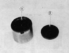
d. Pull out the element.
1. Air filter element
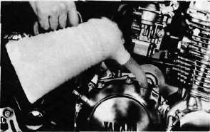
2. Cleaning method
Tap the element lightly to remove most of the dust and dirt; then blow out the remaining dirt with compressed air from the inner surface of the element. If element is damaged, replace it.
3. Reassemble by reversing the removal procedure. Check whether the element is seated completely against the case.
4. The air filter element should be cleaned at the specified intervals.
CAUTION:
The engine should never be run without the air cleaner element installed; excessive piston and/or cylinder wear may result.
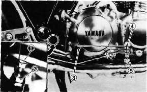
E. SYNCHRONIZATION
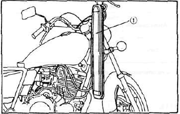
The seat must be opened and the rear of the tank elevated to gain access to the vacuum connections and synchronizing screw of the carburetors.
NOTE:
The valve clearances must be set properly before synchronizing the carburetors.
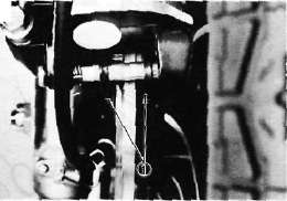
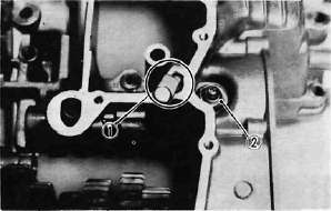
1. Remove the vacuum pipe from the carburetor manifold (No. 3 cylinder) and turn the fuel petcock to "PRI".
2. Remove the rubber caps from the No. 1, 2, and 4 carburetor manifolds.
1. Vacuum pipe 2. Rubber cap
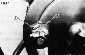
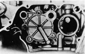
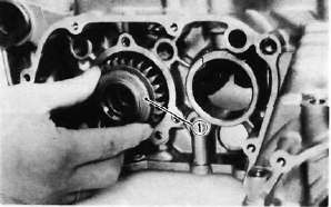
3. Remove either the left or right (but not both) blind plug at the end of the YICS (Yamaha I nduction Control System) passage in the cylinder.
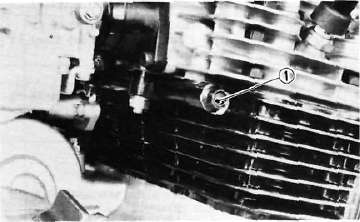
1. Blind plug
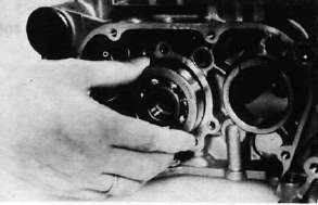
4. Insert the YICS shutoff tool (special tool) fully and flip the locking lever.
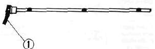
1. Locking lever
5. Connect each vacuum gauge hose to its proper carburetor.
1. Vacuum gauge
6. Start the engine allow it to warm-up for a few minutes. The warm-up is complete when engine responds normally to the throttle opening.
7. Make sure the engine idle speed is 950 ~ 1,000 r/min. If it does not, adjust the idle speed with the throttle stop screw.
NOTE:
With the YICS shutoff tool fitted, the engine speed generally drops a little. Thus, continue with the following steps at idle speed of 950 ~ 1,000 r/min.
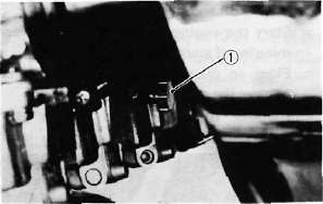
8, Each gauge reading will indicate the same if the carburetors are synchronized. The No. 3 carburetor has no synchronizing screw and the other carburetors are to be synchronized to it in order, one at a time.
First, synchronize carburetor No. 1 to carburetor No. 2 by turning the No. 1 synchronizing screw until both gauges read the same.
Second, in the same way synchronize carburetor No. 4 to carburetor No. 3. Third, by adjusting No.2 screw to watch No. 3 carburetor reading, No. 1 and No. 2 carburetors will both change to match No. 3 carburetor.
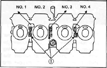
1. Synchronizing screws
9. Remove the YICS shutoff tool and reinstall the blind plug.
Tightening torque: 2.2 m-kg (16.0 ft-lb)
10. Check the idle speed. Adjust if necessary.
Carburetors must be synchronized before setting final idle speed. The idle speed adjustment is made by turning only one throttle stop screw.
a. The engine must be warmed up before setting idle speed.
b. Set the engine idle speed by turning the throttle stop screw in (to increase engine speed) or out (to decrease engine speed).
Standard idle speed: 1,050 ± 50 r/min
1. Throttle stop screw
Carburetor Specification
|
Main jet |
110 |
|
Jet needle |
Y-10 |
|
Starter jet |
#40 |
|
Fuel level |
3± 1 mm (0.118± 0.039 in) |
|
Pilot screw |
Preset |
|
Float valve seat |
0 2.0 |
|
Engine idle speed |
1,050 r/min |
F. Engine Oil
1. Oil level measurement a. Place the motorcycle on the center stand. Warm up the engine for several minutes.
NOTE:
Be sure the motorcycle is positioned straight up when checking the oil level; a slight tilt toward the side can produce false readings.
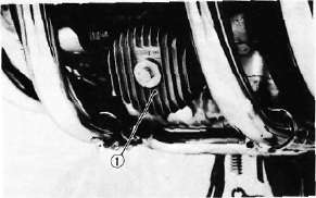
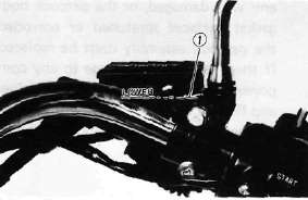
b. With the engine stopped, check the oil level through the level window located at the lower part of the right side crank-case cover.
NOTE:
Wait a few minutes until the oil level settles before checking.
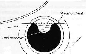
c. The oil level should be maximum level. If the level is lower, add sufficient oil to raise it to the maximum level.
2. Engine oil and oil filter replacement
a. Start, the engine and stop it after a few minutes of warm-up.
b. Place an oil pan under the engine and remove the oil filler cap.
c. Remove the engine and middle gear drain plugs and drain the oil.
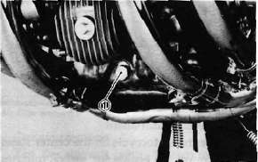
1. Engine drain plug
1. Middle gear drain plug
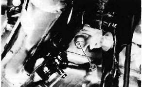
d. Remove the oil filter bolt and filter element.
1. Oil filter cover
e. Re-install the drain plugs (make sure they are tight).
|
Drain plug torque: |
|
|
|
Middle gear: |
1.6 |
m-kg (11.6 ft-lb) |
|
Engine: |
4.3 |
m-kg(31.0ft-lb) |
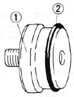
f. Install the new oil filter element, new "O-ring" and filter cover, tighten the oil filter bolt.
Oil filter bolt torque: 1.5 m-kg (11.0 ft-lb)
NOTE:
When installing the filter cover, make sure the "O-ring" is positioned properly and insert the locating projection on it into the corresponding guides on the crankcase.
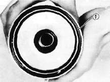
1. Proper O-ring position
g. Add oil through the oil filler hole.
Periodic oil change: 2.35 lit (2.5 US qt.)
With oil filler replacement: 2.65 lit (2.8 US qt.)
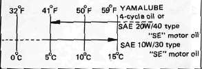
Recommended oil:
h. After replacement of the engine oil, and/ or oil filter, be sure to check for oil leakage. The oil level indicator light should go off after the oil is filled.
CAUTION:
If the indicator light flickers or remains on, the oil level switch may be damaged. Refer to "CHAPTER 6" for corrective action.
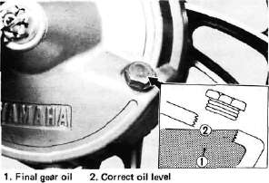
G. Final Gear Oil
1. Oil level measurement
a. Place the motorcycle on a level place and place it on the center stand. The engine should be cool (at atmospheric temperature).
b. Remove the oil filler cap and check the oil level whether it is to the hole brim. If it is not up to this level, replenish oil.
CAUTION:
Take care not to allow foreign material to enter the final gear case.
2. Gear oil replacement
a. Place an oil pan under the final gear case.
b. Remove the final gear oil filler cap and the drain plug, and drain the oil.
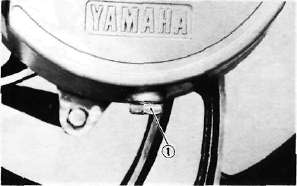
1. Final gear drain plug
c. Reinstall and tighten the final gear drain
plug. d. Fill the gear case to the specified level.
Oil capacity: 0.20 lit (0.21 US qt.) Recommended oil: SAE 80 API "GL-4" Hypoid gear oil
If desired, an SAE 80W/90 hypoid gear oil may be used for all conditions.
e. Reinstall the filler cap securely.
H. Compression Pressure Measurement
Insufficient compression pressure will result in performance loss and may indicate leaking valves or worn or damaged piston rings. Procedure:
1. Make sure the valve clearance is correct.
2. Remove the headlight fuse from the fuse box.
3. Warm up the engine 2 ~ 3 minutes. Stop the engine.
4. Remove the all spark plugs.
5. Install a compression check gauge.
6. Turn over the engine with the electric starter (make sure the battery is fully charged) with the throttle wide open until the pressure indicated on the gauge does not increase further.
Compression pressure (at sea level):
Standard.......11 kg/cm2 (156 psi)
Minimum.......9 kg/cm2 (128 psi)
Maximum......12 kg/cm2 (171 psi)
WARNING:
When cranking the engine, ground the removal spark plug wires to prevent sparking.
1. Compression gauge
7. If the pressure is too low, squirt a few drops of oil into the cylinder being measures. Measure compression again. If there is a higher reading than before (without oil), the piston rings may be worn or damaged. If the pressure remains the same after measuring with the oil, either or both the rings and valves may be the cause.
8. Check each cylinder. Compression pressure should not vary more than specified value from one cylinder to any other cylinder.
Difference in gauge reading: Less than 1 kg/cm2(14 psi)
I. Clutch Adjustment
Free play adjustment
a. Loosen either the handle lever adjuster lock nut or the cable length adjuster lock nut.
b. Turn the cable length adjuster either in or out until proper lever free play is achieved.
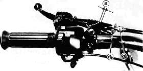
1. Lock nut 2. Adjuster a. 2~3 mm (0.08~0.12 in)
1. Lock nut 2. Adjuster
Chassis Maintenance
Chassis MaintenanceFuel Petcock
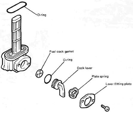
If the fuel petcock is leaking or excessively contaminated, it should be removed from the fuel tank and inspected.
1. Remove the fuel tank and position it so that fuel will not spill when the petcock is removed.
2. Remove the petcock and inspect the filter screen. Replace the filter if seriously contaminated.
3. Remove the screws on the front and rear of the petcock and remove the plate, gaskets, lever, and diaphragm.
4.
Inspect all components and replace any that are damaged. If the
diaphragm is in any way damaged, or the petcock body gasket surfaces
scratched or corroded, the petcock assembly must be replaced. If there
is abrasive damage to any component, the fuel tank must be drained and
flushed.
5. Reassemble the petcock and install it on the fuel tank.
B. Front and Rear Brake
1. Brake adjustment
a.
Front brake lever free play adjustment. The brake can be adjusted by
simply adjusting the free play of the brake lever. The piston in the
caliper moves forward as the brake pad wears out, automatically
adjusting the clearance between the brake pads and brake disc.
CAUTION:
Proper lever free play is essential to avoid excessive brake drag.
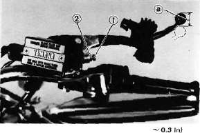
1. Adjuster 2. Lock nut a. 5~8 mm (0.2 ~ 0.3 in)
1) Loosen the adjuster lock nut on the brake lever.
2)
Turn the adjuster so that the brake lever movement at the lever end is
5- 8 mm (0.2 ~ 0.3 in) before the adjuster contacts the master cylinder
piston.
3) After adjusting, tighten the lock nut.
b. Rear brake pedal height adjustment
1) Loosen the adjuster lock nut (for pedal height).
2)
By turning the adjuster bolt clockwise or counterclockwise, adjust the
brake pedal position so that its top end is approximately 20 mm (0.78
in) below the footrest top end.
3) Secure the adjuster lock nut.
WARNING:
After adjusting the pedal height, the brake pedal free play should be adjusted.
c. Rear brake pedal free play adjustment
|
1. Adjuster bolt |
3. Footrest |
|
(for pedal height) |
4. Pedal height 20 mm [0.8 in) |
|
2. Lock nut |
5. Free play 20~ 30 mm (0.8-^ 1.2 in) |
Turn
the adjuster on the brake rod clockwise or counterclockwise to provide
the brake pedal end with a free play of 20 — 30 mm (0.8-1.2 in).
NOTE:
Check to see whether or not the brake light operates correctly after adjusting.
2. Front brake pad and rear brake shoe
check a. Front brake pad
To check, look at the pad in front. If any pad is worn to the wear limit, replace the both pads in the caliper.
Front
1. Wear indicator
b. Rear brake shoe
To
check, see the wear indicator position while depressing the brake
pedal. If the indicator reaches to the wear limit line, replace the
shoes.
1. Wear limit 2. Wear indicator
3. Brake fluid
Insufficient
brake fluid may allow air to enter the brake system, possibly causing
the brake to become ineffective. Check the brake fluid level and
replenish when necessary observing these precautions:
1. Lower level
a.
Use only the designated quality brake fluid; otherwise, the rubber
seals may deteriorate, causing leakage and poor brake performance.
Recommended brake fluid: DOT #3
b.
Refill with the same type and brand of brake fluid; mixing fluids may
result in a harmful chemical reaction and lead to poor performance.
c.
Be careful that water or other contamination does not enter the master
cylinder when refilling. Water will significantly lower the boiling
point and may result in vapor lock.
d. Brake fluid may erode painted surfaces or plastic parts. Always clean up spilled fluid immediately.
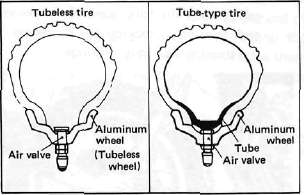
C. Tubeless Tires and Aluminum Wheels
This
motorcycle is equipped with aluminum wheels designed to be compatible
with either tube or tubeless tires. Tubeless tires are installed as
standard equipment.
WARNING:
Do
not attempt to use tubeless tires on a wheel designed for use only with
tube-type tires. Tire failure and personal injury may results from
sudden deflation. Tube-type Wheel — Tube-type tires only Tubeless-type
Wheel — Tube-type or Tubeless tires When using tube-type tires, be sure to install the proper tube also.
To insure maximum performance, long service, and safe operation, note the following precautions:
1. Check tire pressure, before riding, adjust as necessary.
2.
Before operation, always check the tire surfaces for wear and/or
damage; look for cracks, glass, nails, metal fragments, stones, etc.
Correct any such hazard before riding.
3.
Always inspect the aluminum wheels before a ride. Place the motorcycle
on the center stand and check for cracks, bends or warpage of the
wheels. Do not attempt even small repairs to the wheel. If a wheel is
deformed or cracked, it must be replaced.
4.
Tires and wheels should be balanced whenever either one is changed or
replaced. Failure to have a wheel assembly balanced can result in poor
performance, adverse handling characteristics, and shortened tire life.
5. After installing a tire, ride conservatively to allow
the tire to seat itself on the rim properly. Failure to allow proper
seating may cause tire failure resulting in damage to the motorcycle
and injury to the rider.
6. After
repairing or replacing a tire, check to be sure the valve stem lock nut
is securely fastened. If not, torque it as specified.
Tightening torque:
0.15 m-kg (1.1 ft-lb)
D. Front Fork Oil Change
WARNING:
Fork oil leakage can cause loss of stbility and safe handling. Oil may
contaminate front brakes causing loss of braking ability. Have any
problem corrected before operating the motorcycle.
Warning:
Securely support the motorcycle so there is no danger of it falling over.
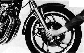
1. Raise
the motorcycle or remove the front wheel so that there is no weight on
the front end of the motorcycle. Remove the handlebar if necessary.
2. Unscrew the rubber cap from the top of each fork and remove it.
1. Rubber cap
3. Keep the valve open by pressing it for several seconds so that the air can be let out of the inner tube.
4. The spring seat is retained by a stopper ring (spring wire clip). It is necessary to depress the spring seat and fork spring with a seat compresser to remove the stopper ring. Remove the stopper ring by carefully prying out one end with a screw-driver.
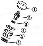
1. Cap 4. Stopper ring
2. Valve 5. Spring seat
3. O-ring 6. O-ring
5. Place an open container under each drain hole. Remove the drain screw.
WARNING:
Do
not allow oil to contact the disc brake components. If any oil should
contact the brake components it must be removed before the motorcycle
is operated. Oil will cause diminished braking capacity and will damage
the rubber components of the brake assembly.
1. Drain screw
6. When most of oil has drained, slowly raise and lower the outer tubes to pump out the remaining oil.
7. Inspect the drain screw gasket. Replace if damaged. Re install the drain screw.
8. Pour the specified amount of oil into the inner tube.
Fork oil capacity: 278 cm3 (9.4 US oz)
Recommended oil: Yamaha fork oil 10 wt or equivalent
9. After filling, slowly pump the forks up and down to distribute the oil.
10. Inspect the O-ring on the spring seat. Replace O-ring if damaged.
1. Spring seat
2. O-ring
11. Reinstall the spring seat and fill the fork with air using a manual air pump.
CAUTION:
Always use a new stopper ring (spring wire circlip).
Maximum air pressure: 1.2 kg/cm2 (17 psi) Do not exceed this amount.
E. Rear Shock Absorber
1. Spring preload
If the spring seat is raised, the spring becomes stiffer and if lowered, it becomes softer.
Standard position — A
A. position — Softest
E. position - Stiffest
WARNING:
Adjust both the right and left sides to the same position.
Compatibility chart
Recommended combinations of the front Use this table as guidance to meet specific rid-fork and the rear shock absorber. ing conditions and motorcycle load.
|
\ |
Front fork |
Rear shock absorber |
Loading condition |
|||
|
Air pressure |
Spring seat |
Solo rider |
With passenger |
With accessory equipment |
With accessory equipments and passenger |
|
|
1 |
0.4 — 0.8 kg/cm2 (5.7-11.4 psi) |
A-C |
O |
|||
|
2 |
0.4- 0.8 kg/cm2 (5.7-11.4 psi) |
A-C |
O |
O |
||
|
3 |
0-4-0.8 kg/cm2 (5.7-11.4 psi) |
C- E |
O |
O |
||
|
4 |
0.8-1.2 kg/cm2 (11.4-17.1 psi) ----------------------- . |
E |
o |
o |
||
F. Steering Head Adjustment
The steering assembly should be checked periodically for looseness.
1. Raise the front end of the motorcycle so that there is no weight on the front wheel.
2. Grasp the bottom of the forks and gently rock the fork assembly backward and forward, checking for looseness in the steering assembly bearings.
3. If there is looseness in the steering head, loosen the steering stem and front fork pinch bolts and steering fitting bolt.
4. Use a steering nut wrench to loosen top steering fitting nut. The top nut serves as a lock nut.
5. Tighten the lower steering fitting nut until the steering head is tight, but does not bind when forks are turned.
6. Retighten the top steering fitting nut, steering fitting bolt and steering stem and front fork pinch bolts, in that order.
7. Recheck steering adjustment to make sure there is no binding when the forks are moved from lock to lock. If necessary, repeat adjustment procedure.
G. Cable Inspection and Lubrication
WARNING:
Damage
to the outer housing of the various cables, may cause corrosion and
often free movement will be obstructed. An unsafe condition may result
so replace such cables as soon as possible.
1. If the inner cables do not operate smoothly, lubricate or replace them.
Recommended lubricant:
Yamaha Chain and Cable Lube or SAE 10W/30 motor oil
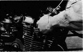
H. Throttle Cable and Grip Lubrication
The throttle twist grip assembly should be greased when the cable is lubricated, since the grip must be removed to get at the end of the throttle cable. Two screws clamp the throttle housing to the handlebar. Once these two are removed, the end of the cable can be held high to pour in several drops of lubricant. With the throttle grip disassembled, coat the metal surface of the grip assembly with a suitable all-purpose grease to cut down friction.
I. Rear Arm Pivot Bearings
The swing arm must pivot freely on its bearings but not have any excess play. Check and adjust pivot bearings if necessary. (Refer to CHAPTER 5. SWING ARM).
J. Brake and Change Pedals/Brake and Clutch Levers
Lubricate the pivoting parts of each lever and pedal.
Recommended lubricant: Yamaha Chain and Cable Lube or SAE 10W/30 motor oil
K.Center and Side Stand Pivots
Lubricate the center and side stands at their pivot points.
Recommended lubricants: Yamaha Chain and Cable Lube or SAE 10W/30 motor oil
Electrical Maintenance
Electrical MaintenanceELECTRICAL
A. Battery
1. The fluid level should be between the upper and lower level marks. Use only distilled water if refilling is necessary.
CAUTION:
Normal tap water contains minerals which are harmful to a battery; therefore, refill only with distilled water.
2. Always make sure the connections are correct when installing the battery. Make sure the breather pipe is properly connected, properly routed, and is not damaged or obstructed.
CAUTION:
The battery must be charged before using to insure maximum performance. Failure to properly charge the battery before first use, or low electrolyte level will cause premature failure of the battery. Charging current: 1.2 amps/10 hrs or until the specific gravity reaches 1.280 at 20°C (68°F)
WARNING:
Battery electrolyte is poisonous and dangerous, causing severe burns, etc. Contains sulfuric acid. Avoid contact with skin, eyes or clothing. Antidote: EXTERNAL-Flush with water.
INTERNAL—Drink large quantities of water or milk. Follow with milk of magnesia, beaten egg or vegetable oil. Call physician immediately.
Eyes: Flush with water for 15 minutes and get prompt medical attention. Batteries produce explosive gasive gases. Keep sparks, flame, cigarettes, etc. away. Ventilate when charging or using in closed space. Always shield eyes when working near batteries. KEEP OUT OF REACH OF CHILDREN.
B. Spark Plug
1. Check the electrode condition and wear, insulator color and electrode gap.
2. Use a wire gauge for measuring the plug gap.
3. If the electrodes become too worn, replace the spark plug.
4. When installing the plug, always clean the gasket surface. Wipe off any grime that might be present on the surface of the spark plug, and torque the spark plug properly.
Standard spark plug:
BP7ES (NGK) or W22EP (ND) Spark plug gap:
0.7 ~ 0.8 mm (0.028 ~ 0.032 in) Spark plug tightening torque:
2.0 m-kg (14.5 ft-lb)
C. Headlight
1. Headlight bulb replacement a. Remove the 2 screws holding the light unit assembly to the headlight body.
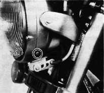
b. Disconnect the lead wires and remove the light unit assembly.
c. Remove the top and bottom fitting screws and the horizontal adjusting screw. Remove the light unit assembly from the headlight rim.
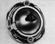
d. Remove the sealed beam unit holding screws. Remove the unit retaining ring and the defective unit.
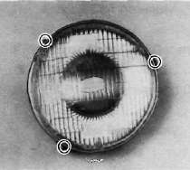
e. Slip a new sealed beam unit into position and secure it with the retaining ring and install it into the headlight rim.
f. Reinstall the light unit assembly to the headlight body. Adjust the headlight beam.
2. Headlight beam adjustment
a. Horizontal adjustment
To adjust the beam to the right, turn the adjusting screw clockwise.
To adjust the beam to the left, turn the screw counterclockwise.
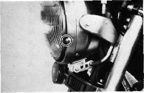
b. Vertical adjustment:
Loosen the adjusting screw under the headlight body. Adjust vertically by moving the headlight body. When proper adjustment is determined, retighten the adjusting screw.
D. Fuse
The fuse block is located under the seat. If any fuse is blown, turn off the ignition switch and the switch in the circuit in question and install a new fuse of proper amperage. Then turn on the switches, and see if the electrical device operates. If the fuse immediately blows again, check the circuit in question (refer to "CHAPTER 6. ELECTRICAL").
WARNING:
Do not use fuses of a higher amperage rating than those recommended. Substitution of a fuse of improper rating can cause extensive electrical system damage and possible fire.
Chapter 3, ENGINE OVERHAULING
Chapter 3, ENGINE OVERHAULINGCHAPTER 3. ENGINE OVERHAULING
Engine Removal
Engine RemovalENGINE REMOVAL
NOTE:
It is not necessary to remove the engine in order to remove the cylinder head, cylinder, or pistons.
A . Preparation for Removal
1 All dirt, mud, dust and foreign material should be thoroughly removed from the exterior of the engine before removal and disassembly. This will help prevent any harmful foreign material from getting into the engine oil.
2. Before the engine removal and disassembly, be sure that you have the proper tools and cleaning equipment so that you can perform a clean and efficient job.
3. During disassembly of the engine, clean and place all of the parts in trays in order of disassembly. This will speed up assembly time and help insure correct reinstall-action of all the engine parts.
4. Place the motorcycle on its center stand. Start the engine and allow it to warm up. Stop the engine and drain the engine and middle gear oil.
5 . Remove the oil filter element from the crankcase.
6. Remove the left and right side covers.
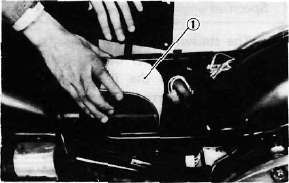
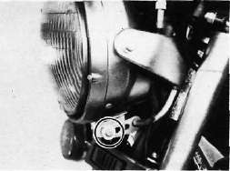
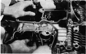
B. Seat and Fuel Tank
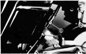
1. Turn the fuel petcock to "ON".
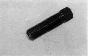
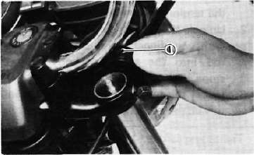
2. Remove the seat and the fuel tank holding bolt. Lift the rear end of the duel tank and disconnect the fuel pipes and vacuum pipe from the petcock.
-1.jpg)
3. Remove the tool tray.
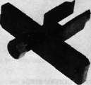
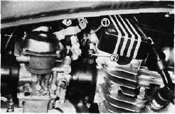
C. Mufflers
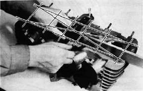
1 Remove the rear brake pedal.
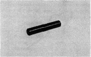
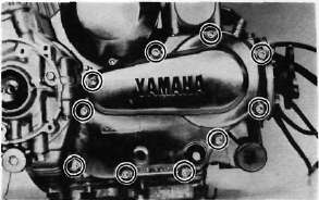
2. Remove the exhaust pipe holding nuts from the cylinder head.
-2.jpg)
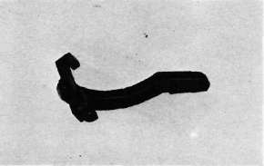
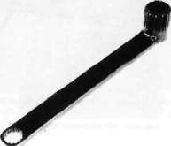
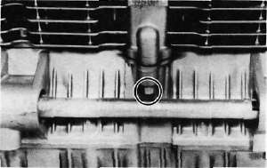
3, Loosen the clamp bolts securing the muffler joints.
-3.jpg)
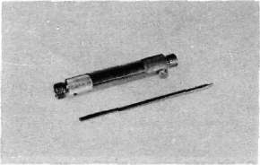
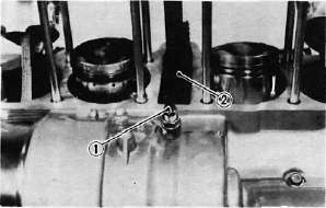
4. Remove the bolts holding the right and left mufflers to the muffler bracket and remove the left and right mufflers.
-4.jpg)
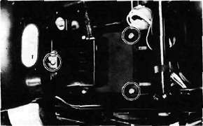
D. Battery Case
1. Remove the negative battery cable from the battery terminal then remove the positive battery plate. Remove the battery.
-5.jpg)
2. Remove the battery case holding bolts and remove the battery case.
-6.jpg)
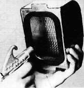
E. Air Cleaner Case
1, Remove the ignitor unit mounting board securing screw and disconnect all connectors. Remove the board assembly.
-7.jpg)
2. Remove the clamps holding the carburetors to the air cleaner case and intake manifolds. Remove the crankcase ventilation hose at the air cleaner case.
-8.jpg)
3. Remove the bolts holding the air cleaner case to the frame (left and upper)
-9.jpg)
NOTE
The engine ground wire is secured together with left side holding bolt.
4. Remove the starter (CHOKE) cable from the carburetor.
5. Remove the air cleaner joint rubbers and pull the carburetor assembly to the rear.
6. Disconnect the throttle cable from the carburetor throttle lever and remove the carburetor assembly to the right.
-10.jpg)
F. Wiring and Cables
1. Disconnect the clutch cable at the crank-case side.
-11.jpg)
2. Remove the spark plug lead wires and the tachometer cable.
-12.jpg)
3. Disconnect the electric starter cable at the starter relay switch.
-13.jpg)
1. Starter relay switch 2. Electric starter cable
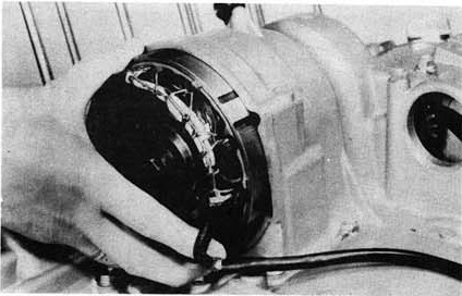
4. Disconnect the pick-up coil and ACG lead wire couplers. Position the disconnect lead wires so that they can be safely removed.
-14.jpg)
CAUTION:
The ACG lead, starter cable, and pickup lead are clamped at the upper cross tube of the frame. Do not forget to remove this clamp before removing the engine.
-15.jpg)
1. Clamp
5. Remove the horn and flasher relay.
-16.jpg)
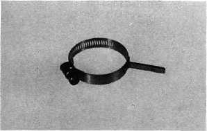
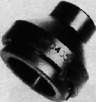
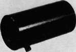
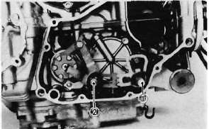
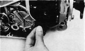
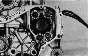
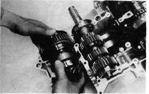
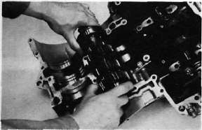
G. Drive Shaft Joint
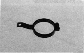
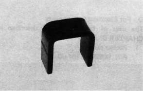
1 Remove the coil spring holding the rubber boot.
2. Pull the rubber boot from the drive shaft coupling to expose the joint bolts.
3. Remove the joint bolts on the drive
-17.jpg)
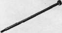
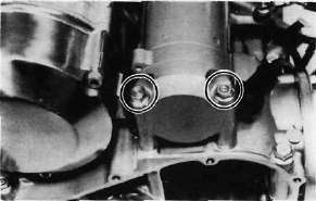
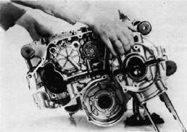
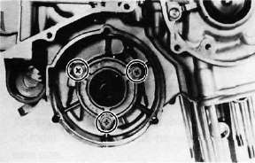
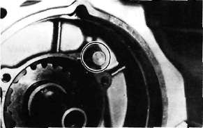
H. Engine Removal
1. Remove the front engine mounting bolts and nuts. Remove the brackets.
-18.jpg)
1. Front engine mounting bolts 2. Engine stay
NOTE:
It is advisable to hold the engine with a suitable garage jack before removing the engine mounting bolts and nuts.
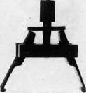
2. Remove the rear engine mounting bolt and right and left footrests. Remove the brake pedal and right side muffler bracket holding bolt and remove the muffler bracket assembly.
-19.jpg)
3. Slide the engine forward slightly and remove the engine to the right.
NOTE:
Position a box or other support to the right side of the motorcycle for the assistance when removing the engine.
Cylinder Head Removal
Cylinder Head RemovalENGINE REMOVAL
NOTE:
It is not necessary to remove the engine in order to remove the cylinder head, cylinder, or pistons.
A . Preparation for Removal
1 All dirt, mud, dust and foreign material should be thoroughly removed from the exterior of the engine before removal and disassembly. This will help prevent any harmful foreign material from getting into the engine oil.
2. Before the engine removal and disassembly, be sure that you have the proper tools and cleaning equipment so that you can perform a clean and efficient job.
3. During disassembly of the engine, clean and place all of the parts in trays in order of disassembly. This will speed up assembly time and help insure correct reinstall-action of all the engine parts.
4. Place the motorcycle on its center stand. Start the engine and allow it to warm up. Stop the engine and drain the engine and middle gear oil.
5 . Remove the oil filter element from the crankcase.
6. Remove the left and right side covers.
B. Seat and Fuel Tank
1. Turn the fuel petcock to "ON".
2. Remove the seat and the fuel tank holding bolt. Lift the rear end of the duel tank and disconnect the fuel pipes and vacuum pipe from the petcock.
3. Remove the tool tray.
C. Mufflers
1 Remove the rear brake pedal.
2. Remove the exhaust pipe holding nuts from the cylinder head.
3, Loosen the clamp bolts securing the muffler joints.
4. Remove the bolts holding the right and left mufflers to the muffler bracket and remove the left and right mufflers.
D. Battery Case
1. Remove the negative battery cable from the battery terminal then remove the positive battery plate. Remove the battery.
2. Remove the battery case holding bolts and remove the battery case.
E. Air Cleaner Case
1, Remove the ignitor unit mounting board securing screw and disconnect all connectors. Remove the board assembly.
2. Remove the clamps holding the carburetors to the air cleaner case and intake manifolds. Remove the crankcase ventilation hose at the air cleaner case.
3. Remove the bolts holding the air cleaner case to the frame (left and upper)
NOTE
The engine ground wire is secured together with left side holding bolt.
4. Remove the starter (CHOKE) cable from the carburetor.
5. Remove the air cleaner joint rubbers and pull the carburetor assembly to the rear.
6. Disconnect the throttle cable from the carburetor throttle lever and remove the carburetor assembly to the right.
F. Wiring and Cables
1. Disconnect the clutch cable at the crank-case side.
2. Remove the spark plug lead wires and the tachometer cable.
3. Disconnect the electric starter cable at the starter relay switch.
1. Starter relay switch 2. Electric starter cable
4. Disconnect the pick-up coil and ACG lead wire couplers. Position the disconnect lead wires so that they can be safely removed.
CAUTION:
The ACG lead, starter cable, and pickup lead are clamped at the upper cross tube of the frame. Do not forget to remove this clamp before removing the engine.
1. Clamp
5. Remove the horn and flasher relay.
G. Drive Shaft Joint
1 Remove the coil spring holding the rubber boot.
2. Pull the rubber boot from the drive shaft coupling to expose the joint bolts.
3. Remove the joint bolts on the drive
H. Engine Removal
1. Remove the front engine mounting bolts and nuts. Remove the brackets.
1. Front engine mounting bolts 2. Engine stay
NOTE:
It is advisable to hold the engine with a suitable garage jack before removing the engine mounting bolts and nuts.
2. Remove the rear engine mounting bolt and right and left footrests. Remove the brake pedal and right side muffler bracket holding bolt and remove the muffler bracket assembly.
3. Slide the engine forward slightly and remove the engine to the right.
NOTE:
Position a box or other support to the right side of the motorcycle for the assistance when removing the engine.
Cylinder and Cylinder Head Disassembly
Cylinder and Cylinder Head Disassembly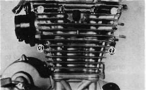
13. Remove the front cylinder holding nut and remove the cylinder assembly. It may be necessary to tap the cylinder lightly to loosen it from the base gasket.
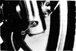
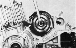
14. Remove the rear cam chain guide by loosening the holding bolt.
1. Holding bolt 2. Rear cam chain guide
B. Cylinder Head Disassembly
1. Remove the valve lifters and pads. Be careful not to scratch the lifter bodies or lifter bores in the cylinder head. Be very careful to identify each lifters position so that it may be returned to its original place.
1. Valve filter 2. Adjusting pad
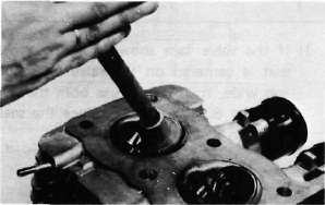
2. Mount the valve spring compressor on the head and depress each valve spring. Take out the retainer and valve spring with tweezers.
1. Valve spring compressor
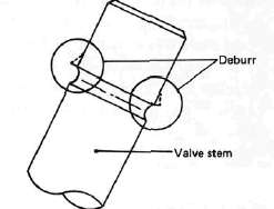
3. Remove valves.
NOTE:
Deburr any deformed valve stem end. Use an oil stone to smooth the stem end. This will help prevent damage to the valve guide during valve removal.
4. Use a small box to hold the parts and identify the original position of each lifter and valve. Be very careful not to mix the location of these components.
Piston, Pickup Coil, Shifter, Starter, Generator and Clutch Removal
Piston, Pickup Coil, Shifter, Starter, Generator and Clutch RemovalC. Piston
1. Mark each piston to aid in reassembly.
2. Place a clean towel or rag into the crank-case to keep circlips and material from falling into the engine.
3. Remove piston pin clips, piston pins, and pistons.
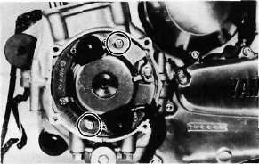
D. Pick-up Coil Assembly
1. Remove the alien bolt that holds the timing plate.
2. Remove the pick-up coil securing screws and remove the pick-up coil assembly.
E. Shifter
1. Remove the change pedal.
2. Remove the left crankcase cover.
3. Remove the shift lever assembly and shift shaft assembly.
1. Shift lever assembly 2. Shift shaft assembly
4. Remove the middle gear case oil level maintaining plug.
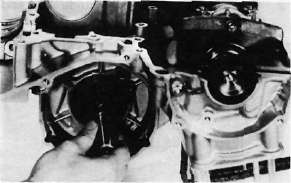
F. Starter Motor and Generator
1. Remove the starter motor securing bolts and remove the motor assembly.
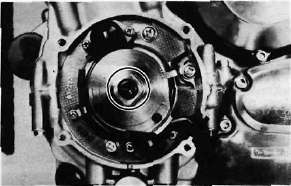
2. Remove the generator cover and stator coil assembly.
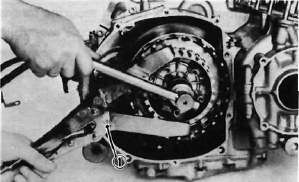
3. Install the rotor holding tool (special tool) on the rotor as shown and remove the rotor holding bolt.
1. Rotor holding tool
4. Invert the holding tool as shown and insert the rotor puller adapter (special tool) into the rotor shaft and screw in the rotor puller (special tool). Remove the rotor.

1. Rotor puller adapter
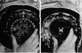
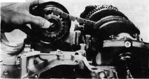
G. Clutch
1. Remove right crankcase cover.
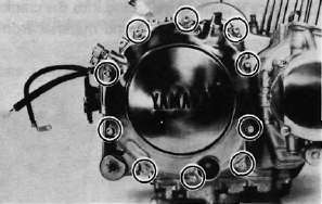
2. Release the tension evenly on the 6 mm bolts and remove the clutch pressure plate and clutch springs.

3. Remove the friction plates and clutch plates.
4. Straighten the lock washer tab. Use the clutch boss holder (special tool) to hold the clutch boss and remove the lock nut and lock washer.
1. Clutch boss holder
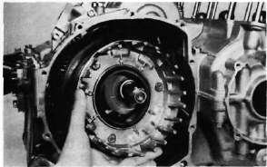
5. Remove the clutch boss and spacer.
6. Screw in a suitable length of 6 mm bolt into the one of the threaded holes on the collar and pull out the collar and needle bearing from the primary driven gear.
1. Collar
7. Remove the primary driven gear assembly and oil pump drive sprocket.
Oil Pump and Middle Gear Disassembly
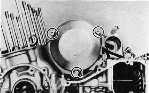
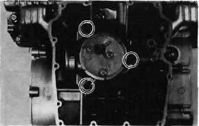
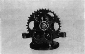
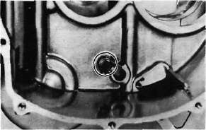
Oil Pump and Middle Gear DisassemblyH. Oil Pump Removal and Disassembly
1. Remove the strainer cover. Note the wire harness clip position.
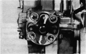
2. Remove the oil pump securing bolts and remove the sprocket cover and oil pump assembly.
CAUTION:
Do not attempt to remove the strainer screen as it is permanently fitted onto the pump housing. If the pump housing and/or any parts of the pump are damaged, the pump assembly must be replaced with a new one.
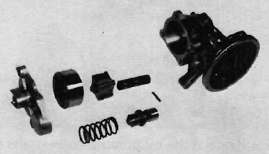
3. Remove the oil pump driven sprocket.
4, Remove the oil pump cover and rotor assembly.
5. Remove the pressure relief valve spring and plunger.
I. Middle Gear
1. Remove the middle driven gear housing holding bolts.
2. Remove the middle driven gear housing assembly and shims.
NOTE:
If it is difficult to remove housing assembly, loosen the two crankcase bolts located near the middle driven gear housing.
3. Remove "TORX" screws holding the middle drive gear assembly.
4. Remove the bearing retainers.
Upper Crankcase Disassembly
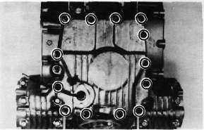
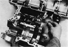
Upper Crankcase DisassemblyJ. Crankcase Disassembly
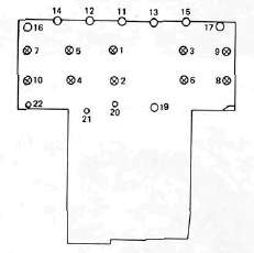
1. Remove the upper crankcase bolts, starting the highest numbered bolt. Turn over the engine and remove the lower crankcase bolts,
XJ650
CRANKCASE TORQUE SEQUENCE
UPPER CASE
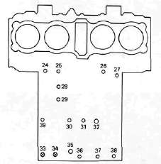
LOWERCASE
2. Separate the lower case from the engine. Use a soft rubber hammer to carefully separate the crankcase.
K. Upper Crankcase
1. Remove the middle drive gear and damper assembly.
2. Remove the transmission main shaft assembly.
3. Remove the A.C.G. shaft cover.
4, Remove the oil spray nozzle.
5. Carefully remove the A.C.G. shaft from the gear.
6. Remove the gear from the chain.
7. Straighten the lock washer tube and remove the bolt securing the starter idle gear shaft. Remove the shaft and starter idle gear.
Lower Crankcase Disassembly
Lower Crankcase DisassemblyL. Lower Crankcase
1. Remove the dowel pin and "O-ring".
2. Remove the shift fork guide bar and shift forks. The shift forks are identified by numbers cast on their sides.
3. Remove the bolt securing the shift cam locating pin and remove the stopper plate and locating pin.
4. Remove the neutral switch.
1. Shift cam locating pin 2. Neutral switch
5. Pull out the shift cam.
6. Remove the driven shaft bearing cover holding screws and remove the bearing cover.
7. Remove the bearing and 5th wheel gear from the driven shaft and pull out the driven shaft assembly.
1. 5th wheel gear
Cylinder Head and Valves -- Inspection & Repair
Cylinder Head and Valves -- Inspection & RepairINSPECTION AND REPAIR
A. Cylinder Head Cover
Place head cover on a surface plate. There should be no warpage. Correct by re-surfacing as follows:
Place #400 or #600 grit wet sandpaper on surface plate and re-surface head cover using a figure-eight sanding pattern. Rotate head cover several times to avoid removing too much material from one side.
B. Cylinder Head
1. Using a rounded scraper, remove carbon deposits from combustion chamber. Take care to avoid damaging spark plug threads and valve seats. Do not use a sharp instrument. Avoid scratching the aluminum.
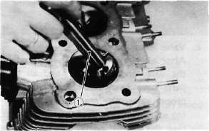
2. Check the cylinder head warpage with a straight edge as shown.
The warpage should not exceed the specified limit, if necessary resurface. If the warpage exceeds allowable limit, the cylinder head should be replaced with a new one.
Cylinder head warpage: less than 0.05 mm (0.002 in) Allowable limit: 0.25 mm (0.010 in)
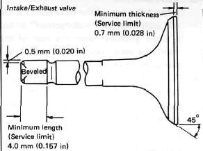
C. Valve, Valve Guide, and Valve Seat
1. Check the valve face and the stem end for wear. If the valve face and/or the stem end are pitted or worn, regrind the valve with a valve refacer. Replace the valve if any dimension exceeds the specifications in the illustration.
2. Valve stem wear must be measured and then combined with valve guide measurements to guide clearance. This clearance must be within tolerances. If it exceeds the maximum limit, then replace either or both valve and guide, as necessary.

|
|
Valve Stem Clearance |
Maximum |
|
Intake |
0.010 — 0.037 mm (0.0004-0.0015 in) |
0.10 mm (0.004 in) |
|
Exhaust |
0.025-0.052 mm (0.0010-0.0020 in) |
0.12 mm (0.005 in) |
3. Valve stem end
Inspect the end of the valve stem. If the end appears to be "mushroomed" or has a larger diameter than the rest of the stem, the valve, valve guide, and oil seal should be replaced.
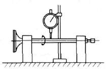
4. Turn valve on "V" blocks and measure the amount of stem runout with a dial gauge. If it exceeds the maximum limit, replace the valve.
Maximum valve stem runout: 0.03 mm (0.0012 in)
5. Valve guide and valve oil seal replacement If oil leaks into the cylinder through a valve due to a worn valve guide, or if a valve is replaced, the valve guide should also be replaced.
NOTE:
The valve oil seal should be replaced whenever a valve is removed or replaced.
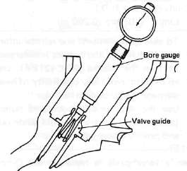
a. Measure valve guide inside diameter with a small bore gauge. If it exceeds the limit, replace with an oversize valve guide.
Guide diameter (I.D.):
Limit: 7.10 mm (0.280 in)
b. To ease guide removal and reinstallation, and to maintain the correct interference fit, heat the head to 100°C (212°F). Use an oven to avoid any possibility of head warpage due to uneven heating.
c. Use the appropriate shouldered punch (special tool) to drive the old guide out and drive the new guide in.
NOTE:
When a valve guide is replaced, the O-ring should also be replaced.
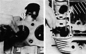
1. Valve guide remover
2. Valve guide installer
d. After installing the valve guide, use the 7 mm reamer (special tool) to obtain the proper valve guide to valve stem clearance.
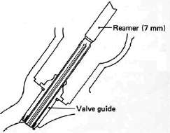
e. After installing the valve guide in the cylinder head, the valve seat must be recut. The valve should be lapped to the new seat.
6. Grinding the Valve Seat
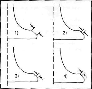
a. The valve seat is subject to severe wear. Whenever the valve is replaced or the valve face is re-surfaced (see caution) the valve seat should be re-surfaced at a 45° angle. If a new valve guide has been installed the valve seat must be recut to guarantee complete sealing between the valve face and seat.
CAUTION:
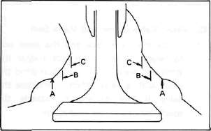
If the valve seat is obviously pitted or worn, it should be cleaned with a valve seat cutter. Use the 45° cutter, and when twisting the cutter, keep an even downward pressure to prevent chatter marks.
If cutting section "A" of the valve seat, use 30° cutter. If cutting section "B", use the 45° cutter. If cutting section "C" use 60° cutter.
b. Measure valve seat width. Apply mechanic's bluing dye (such as Dykem) to the valve face and valve seat, apply a very small amount of fine grinding compound around the surface of the valve face insert the valve into position, and spin the valve quickly back and forth. Lift the valve, clean off all grinding compound, and check valve seat width. The valve seat and valve face will have removed bluing wherever they contacted each other. Measure the seat width with vernier calipers. It should measure approximately 1.1 mm (0.0433 in). Also, the seat should be uniform in contact area. If valve seat width varies, or if pits still exist, further cutting will be necessary. Remove just enough material to achieve a satisfactory seat.
|
|
Standard Width |
Wear Limit |
|
Seat width |
1.0 ±0.1 mm (0.0394 ± 0.0039in) |
2.0 mm (0.080 in) |
a. Seat width
c. If the valve seat is uniform around the perimeter of the valve face, but is too wide or not centered on the valve face, it must be altered. Use either the 30°, 45° or 60° cutters to correct the improper seat location in the manner described below:
1) If the valve face shows that the valve seat is centered on the valve face, but too wide, then lightly use both the 30° and the 60° cutters to reduce the seat width to 1.1 mm (0.0433 in).
1. Valve seat cutter
2) If the seat shows to be in the middle of the valve face, but too narrow, use the 45°cutter until the width equals 1.1 mm (0.0433 in).
3) If the seat is too narrow and right up near the valve margin, then first use the 30° cutter and then the 45° cutter to get the correct seat width.
4) If the seat is too narrow and down near the bottom edge of the valve face, then first use the 60° cutter and then the 45° cutter.
7. Lapping the valve/valve seat assembly a. The valve/valve seat assembly should be lapped if neither the seat nor the valve face are severely worn.
b. Apply a small amount of coarse lapping compound to valve face. Insert the valve into the head. Rotate the valve until the valve and valve seat are evenly polished. Clean off the coarse compound, then follow the same procedure with fine compound.
Continue lapping until the valve face shows a complete and smooth surface all the way around. Clean off the compound material. Apply bluing dye to the valve face and seat and rotate the valve face for full seat contact which is indicated by a grey surface all around the valve face where the bluing has been rubbed away.
c. Valve leakage check
After all work has been performed on the valve and valve seat, and all head parts have been assembled, check for proper valve/valve seat sealing by pouring solvent into each of the intake ports, then the exhaust ports. There should be no leakage past the seat. If fluid leaks, disassemble and continue to lap with fine lapping compound. Clean all parts thoroughly, reassemble and check again with solvent. Repeat this procedure as often as necessary to obtain a satisfactory seal.
Valve Springs and Lifters, Camshafts, Chain and Guides -- Inspection and Repair
Valve Springs and Lifters, Camshafts, Chain and Guides -- Inspection and RepairD. Valve Spring and Lifters
1. Checking the valve springs
a. This engine uses two springs of different sizes to prevent valve float or surging. The valve spring specifications show the basic value characteristics.
b. Even though the spring is constructed of durable spring steel, it gradually loses some of it's tension. This is evidenced by a gradual shortening of free length. Use a vernier caliper to measure spring free length. If the free length of any spring has decreased more than 2 mm (0.080 in) from its specification replace it.
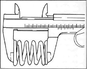
c. Another symptom of a fatigued spring is insufficient spring pressure when compressed. This can be checked using a valve spring compression rate gauge. Test each spring individually. Place it in the gauge and compress the spring first to the specified compressed length with the valve closed (all spring specifications can be found in the previous section, Valve Spring), then to the length with the valve open. Note the poundage indicated on the scale at each setting. Use this procedure with the outer springs, then the inner springs.
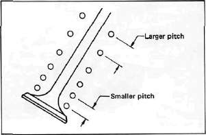
NOTE:
All valve springs must be installed with larger pitch upward as shown.
|
Valve Spring Specifications |
||
|
|
OUTER |
INNER |
|
Free length |
39.5 mm (1.55 in) |
35.9 mm (1.413 in) |
|
Installed length (valve closed) |
34.0 mm (1.339 in) |
31.0 mm (1.220 in) |
|
Installed pressure |
19.1 kg (42.1 lb) |
9.0 kg (19.8 1b) |
|
Allowable tilt from vertical |
1.6° |
|
2. Valve lifter
a. Check each valve lifter for scratches or other damage. If the lifter is damaged in any way, the cylinder head surface in which it rides is probably also damaged. If the damage is severe, it may be necessary to replace both the lifter and the cylinder head.
NOTE:
For proper valve lifter-to-head clearance, always install lifters on their original valves.
E. Camshafts, Cam chain and Cam Sprockets
1. Camshaft
a. The cam lobe metal surface may have a blue discoloration due to excessive friction. The metal surface could also start to flake off or become pitted.
b. If any of the above wear conditions are readily visible, the camshaft should be replaced.
c. Even though the cam lobe surface appears to be in satisfactory condition, the lobes should be measured with a micrometer. Cam lobe wear can occur without scarring the surface. If this wear exceeds a pre-determined amount, valve timing and lift are affected. Replace the camshaft if wear exceeds the limits.
d. Install the camshaft on the cylinder head. Place a strip of Plastigage between camshaft and camshaft cap as illustrated (lengthwise along camshaft). Tighten the nuts with specified torque. Remove the camshaft cap and determine the clearance by measuring the width of the flattened Plastigage.
Cap nut tightening torque: 1.0m-kg (7.2ft-lb)
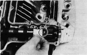
1. Plastigage
NOTE:
Do not turn camshaft when measuring clearance with Plastigage.
Camshaft-to-cap clearance:
|
Standard: |
0.020-0.054 mm |
|
|
(0.0008- 0.0021 in) |
|
Maximum: |
0.160 mm (0.006 in) |
If the camshaft-to-cap clearance exceeds specification, measure camshaft bearing surface diameter.
Bearing surface diameter:
|
Standard: |
24.967-24.980 mm |
|
|
(0.9830-0.9835 in) |
1) If camshaft diameter is less than specification, causing excessive clearance, replace camshaft.
2) If camshaft is within specification and camshaft-to-cap clearance is excessive, replace cylinder head.
2. Cam chain
Except in cases of oil starvation, the cam chain wears very little. If the cam chain has stretched excessively and it is difficult to keep the proper cam chain tension, the chain should be replaced.
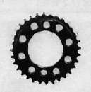
3. Cam sprockets
Check cam sprockets for obvious wear.
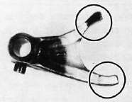
4, Cam chain dampers and tensioner
Inspect the top cam chain damper (stopper guide) and two (2) vertical (slipper-type) dampers for excessive wear. Any that shows excessive wear should be replaced. Worn dampers may indicate an improperly adjusted or worn-out cam chain.
Cylinder and Piston -- Inspection and Repair
Cylinder and Piston -- Inspection and RepairF. Cylinder
1. Inspect the cylinder walls for scratches. If vertical scratches are evident, the cylinder wall should be rebored or the cylinder should be replaced.
2. Measure cylinder wall wear as shown. If wear is excessive, compression pressure will decrease. Rebore the cylinder wall and replace the piston and piston rings. Cylinder wear should be measured at three depths with a cylinder bore gauge. (See illustration.)
|
|
Standard |
Wear Limit |
|
Cylinder bore |
63.00 mm (2.480 in) |
63.10 mm (2.484 in) |
|
Cylinder taper |
— |
0.05 mm (0.002 in) |
|
Cylinder out-of-round |
— |
0.01 mm (0.0004 in) |
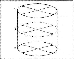
If the cylinder wall is worn more than the wear limit, it should be rebored.
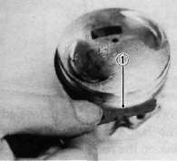
G. Piston and Piston Rings
1. Piston
a. Measure the outside diameter of the piston at the piston skirt. Measurement should be made at a point 7.5 mm (0.3 in) above the bottom edge of the piston. Place the micrometer at right angles to the piston pin.
|
Standard |
63.00 mm (2.480 in) |
|
Oversize 1 |
63.25 mm (2.490 in) |
|
Oversize 2 |
63.50 mm (2.500 in) |
|
Oversize 3 |
63.75 mm (2.510 in) |
|
Oversize 4 |
64.00 mm (2.520 in) |
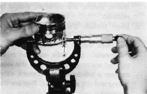
a. 7.5 mm (0.3 in)
b. Determine piston clearance as follows:
Minimum bore measurement - Maximum piston measurement = Piston clearance
EXAMPLE:
63.0 mm (2.4803 in) - 62.96 mm (2.4787 in) = 0.04 mm (0.0016 in)
Piston clearance
Piston clearance:
Standard: 0.030~ 0.050 mm (0.0012~ 0.0020 in)
Service limit: 0.1 mm (0.0039 in)
c. Piston ring/ring groove fit must have correct clearance. If the piston and ring have already been used, the ring must be removed and the ring groove cleaned of carbon. The ring should then be reinstalled. Use a feeler gauge to measure the gap between the ring and the land.
|
Side clearance |
Top |
0.03- 0.07 mm (0.0012- 0.0028 in) |
|
2nd |
0.02-0.06 mm (0.0008- 0.0024 in) |
1. Feeler gauge
2. Piston ring
a. The oversize top and middle ring sizes are stamped on top of the ring.
|
Oversize 1 |
0.25 mm (0.0098 in) |
|
Oversize 2 |
0.50 mm (0.0197 in) |
|
Oversize 3 |
0.75 mm (0.0295 in) |
|
Oversize 4 |
1.00 mm (0.0394 in) |
b. The expander spacer of the bottom ring (oil control ring) is color-coded to identify sizes.
The color mark is painted on the expander spacer.
|
Size |
Color |
|
Oversize 1 |
Brown |
|
Oversize 2 |
Blue |
|
Oversize 3 |
Black |
|
Oversize 4 |
Yellow |
c. Push the ring into the bore and check end gap clearance with a feeler gauge.
NOTE:
The end gap on the expander spacer of the oil control ring is unmeasurable. If the oil control ring rails show excessive gap, all three components should be replaced.
|
|
||
|
|
Standard |
Limit |
|
Top/2nd ring |
0.15 — 0.35 mm (0.006- 0.014 in) |
1.0 mm (0.039 in) |
|
Oil control (Rails) |
0.3-0.9 mm (0.012-0.035 in) |
1.5 mm (0.059 in) |
H. Piston Pin
1. Apply a light film of oil to pin. Install in connecting rod small end. Check for play. There should be no noticeable vertical play. If play exists, check connecting rod small end for wear. Replace pin and connecting rod as required.
2. The piston pin should have no noticeable free play in piston. If the piston pin is loose, replace the pin and/or the piston.
Crankshaft, Con rods and Bearings -- Inspection and Repair
Crankshaft, Con rods and Bearings -- Inspection and RepairI. Crankshaft
1. Crankshaft run-out
Support the crankshaft at both ends on V-blocks. Measure the amount of crankshaft run-out on the main bearing journals with a dial gauge while rotating crankshaft.
Run-out limit: 0.040 mm (0.0016 in)
If run-out exceeds limit, replace crankshaft.
2. Inspection of bearings
Check the bearings. If the inner or outer surface is burned, flaked, rough, scratched or worn, the bearings should be replaced.
replaced. 3. Measuring main bearing oil clearance
a. Clean all crankshaft and crankcase journal surfaces.
b. Place upper crankcase half upside-down on a bench. Install bearing inserts into top crankcase.
c. Install crankshaft into upper crankcase.
d. Place Plastigage on crankshaft journal surface to be inspected.
NOTE:
Do not move crankshaft until clearance check has been completed.
e. Install bearings into bottom crankcase. Carefully, place lower crankcase onto upper crankcase.
f. Install crankcase holding bolts 1 through 10. Tighten to full torque in torque sequence cast on crankcase.
Crankcase torque (8 mm bolt): 2.4 m-kg (17.5 ft-lb)
g. Remove bolts in reverse assembly order (10,9,8... etc.)
h. Carefully remove lower crankcase. Measure width of Plastigage on crankshaft journals to determine clearance.
Main bearing oil clearance: 0.040 - 0.064 mm (0.0016-0.0025 in)
1. Plastigage
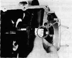
4. Crankshaft main bearing selection a. Numbers used to indicate crankshaft journal sizes are stamped on the L.H. crank web. The first five (5) are main bearing journal numbers, starting with the left journal. The four (4) rod bearing journal numbers follow in the same sequence.
The upper crankcase half is numbered 4, 5, or 6 as shown.
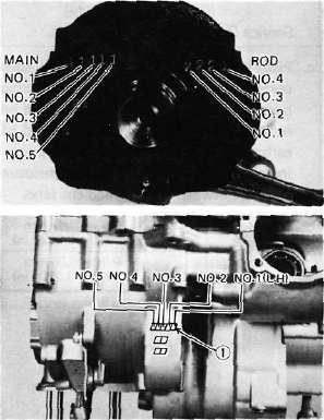
1. Main bearing numbers
b. The connecting rods are numbered 4 or 5. The numbers for rods are stamped with ink on the rod itself.
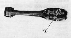
1. Connecting rod size number
c. The proper bearing selection is made by subtracting the crankshaft journal number from the crankcase or rod size number. Use the color code to choose the proper bearing.
EXAMPLE:
Rod No. (Minus) Journal No. = Bearing No. 5-2 = 3 No. 3 bearing is Brown. Use Brown bearing inserts.
|
BEARING COLOR CODE |
|
|
No. 1 |
Blue |
|
No. 2 |
Black |
|
No. 3 |
Brown |
|
No. 4 |
Green |
|
*No. 5 |
Yellow |
#For crankshaft main bearing only.
d. When assembling, apply a liberal coat of motor oil to all bearing surfaces.
NOTE:
When applying final torque to the rod caps, observe the following procedures:
e. Apply molybdenum disulfide grease to connecting rod bolt threads. Apply torque evenly to both ends of the cap. While tightening, if a torque of 2.0 m-kg (14.5 ft-lb) or more is reached, DO NOT STOP tightening until final torque is reached. If tightening is interrupted between 2.0 m-kg and 2.5 m-kg, loosen the nut to less than 2.0 m-kg and start again. Tighten to full torque specification without pausing.
Oil Pump and Clutch -- Inspection and Repair
Oil Pump and Clutch -- Inspection and RepairJ. Oil Pump
1. Check the clearance between housing and outer rotor.
|
Standard clearance: |
|
0.09 ~ 0.15 mm |
|
(0.0035 ~ 0.0059 in) |
2. Check the clearance between outer rotor and inner rotor.
Standard clearance
0.12 mm (0.005 in) or less
3. Check the plunger for scratches and wear.
1. Relief valve plunger
K. Clutch
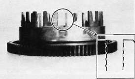
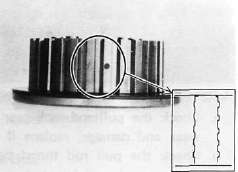
1. Clutch housing
a. Check the dogs on the clutch housing. Look for cracks and signs of galling on edges. If damage is moderate, deburr. If severe, replace the clutch housing.
NOTE:
Galling on the friction plate dogs of the clutch housing will cause erratic clutch operation.
b. Check the clutch housing bearing for damage. If damaged replace bearing.
2. Clutch boss
a. The clutch boss contains a built-in damper beneath the first clutch plate (clutch plate 2). It is not normally necessary to remove the circlip and disassemble the built-in damper unless there is serious clutch chattering.
b. Check splines on clutch boss for galling. If damage is slight to moderate, deburr; if it is severe, replace clutch boss.
NOTE:
Galling on clutch plate splines will cause erratic operation.
3. Friction and clutch plates
Check clutch steel plates and friction plates for heat damage. Measure friction plate thickness at 3 or 4 points. Measure
clutch plates for warpage with a dial gauge and stand. Replace clutch plate or friction plates as a set if any is faulty or beyond wear limits.
|
|
Standard |
Wear limit |
|
Friction plate thickness |
3.0 mm (0.12 in) |
2.8 mm (0.11 in) |
|
Clutch plate warp limit |
— |
0.05 mm (0.0020 in) |
1. Feeler gauge
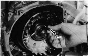
4. Clutch actuating mechanism
1. Plate washer 2. Thrust bearing 3. Pull rod
a. Check the pull rod rack gear teeth for wear and damage, replace if damaged.
b. Check the pull rod thrust bearing for damage, replace if damaged.
c. Check the clutch lever shaft pinion gear teeth for damage, replace if damaged.
5. Clutch springs
Measure the clutch spring free length. Replace the springs as a set if any is less than minimum free length.
Clutch spring minimum length: 39.1 mm (1.539 in)
Transmission -- Inspection and Repair
Transmission -- Inspection and RepairL. Transmission
1. Inspect each shift fork for signs of galling on gear contact surfaces. Check for bending. Make sure each fork slides freely on its guide bar.
2. Roll the guide bar across a surface place. If the bar is bent, replace.
3. Check the shift cam grooves for signs of wear or damage. If any profile has excessive wear and/or damage, replace cam.
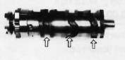
4. Check the cam followers on each shift fork for wear. Check the ends that ride in the grooves in the shift cam. If they are worn or damaged, replace the shift forks.
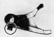
5. Check shift cam dowel pins and side plate for looseness, damage or wear. Replace as required.
6. Check the shift cam stopper plate and circlip and stopper for wear. Replace as required.
7. Check the transmission shafts using a centering device and dial gauge. If any shaft is bent beyond specified limit, replace shaft.
Maximum run-out: 0.08 mm (0.0031 in)
8. Carefully inspect each gear. Look for signs of obvious heat damage (blue discoloration). Check the gear teeth for signs of pitting, galling or other extreme wear. Replace as required.
9. Check to see that each gear moves freely on its shaft.
10. Check to see that all washers and clips are properly installed and undamaged. Replace bent or loose clips and bent washers.
11. Check to see that each gear properly engages its counterpart on the shaft. Check the mating dogs for rounded edges, cracks, or missing portions. Replace as required.
M. Starter Drivers
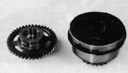
1. Electric starter clutch and gears
a. Check the surface of the idle gear for pitting or other damage. If severe, replace the gear.
b. Check the spring caps and the springs for deformation or damage. If severe, replace as necessary.
c. Check the starter clutch bolts (alien screw) for looseness. If loose, remove the bolts and replace with new bolts. Apply a thread locking compound such as "LOCTITE" to threads and tighten to specified torque. Stake over the end of the bolts.
Starter clutch bolt torque: 3.0 m-kg (21.7 ft-lb)
d. Check the "HY-VO" chain for damage and wear, replace if damaged.
e. Check the "HY-VO" chain guide for damage, replace if damaged.
N. Crankcases and Strainer Cover
1. Check crankcase for cracks or other damage.
2. Clean all oil passages and blow out with compressed air.
3. Strainer cover: Apply a thread locking compound such as "LOCTITE" to strainer cover bolts during reassembly.
O. Bearing and Oil Seals
1. After cleaning and lubricating bearings, rotate inner race with a finger. If rough spots are felt, replace the bearing.
NOTE:
Bearings are most easily removed or installed if the housings are first heated to approximately 95°~12E?C (200°~250°F). Bring the case up to proper temperature slowly. Use an oven to avoid distortion.
2. Check oil seal lips for damage and wear. Replace as required.
Middle Gear -- Inspection and Repair
Middle Gear -- Inspection and RepairP. Middle Gear
1. Damper disassembly
NOTE:
Disassembly of the middle gear damper requires the damper compressor (special tool) and a hydraulic press.
a. Place the middle drive shaft in a press with the damper compressor (special tool) in place as shown.
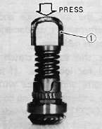
1. Damper compressor
b. Press the damper spring and remove the spring retainers.
c. Remove the spring seat, spring, and damper cams from the drive shaft.
2. Inspection
a. Inspect the damper cam surfaces. Check for smooth cam action and excessive wear on the cam surface. If cam surface is severely worn, replace damper assembly.
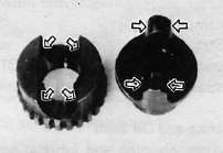
b. Inspect the damper spring for fatigue, wear and damage. Replace as necessary.
c. Check bearing movement for damage to balls, rouge spots, bearing looseness. Inspect gear teeth. If any gear tooth and/or bearing are damaged, the gear set and/or bearing must be replaced.
3. Middle drive/driven shaft bearing removal
CAUTION:
The following procedures should be performed only if the bearing or gear is to be replaced.
a. Middle drive gear
1) Bend down the locking collar of the nut with a suitable center punch.
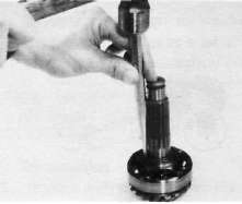
2) Support the middle drive shaft holder (special tool) in a vise securely and put
the drive pinion on it as shown. Remove the bearing holding nut with the 46 mm socket (special socket) and remove the bearing.
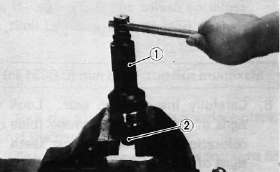
1. Middle drive shaft nut wrench (46 mm socket)
2. Middle drive shaft holder
b. Middle driven gear
1) Support the drive flange in a vise
securely. Remove the flange holding nut.
CAUTION:
This holding nut has been locked with a thread locking compound, when reinstalling do not forget to apply a thread locking compound such as "LOCTITE" and punch.
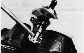
2) Remove the drive flange from the driven shaft.
NOTE:
Driven gear shaft bearing should be replaced together with a bearing housing.
4. Middle gear reassembly
a. Middle drive gear bearing and damper
1) Install the bearing onto the drive pinion and secure it with a new lock nut using the middle drive shaft holder and special socket.
Tightening torque:
11 m-kg (80 ft-lb)
2) Stake the locking collar of the nut to the slot on the drive pinion shaft.
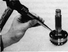
3) Install the driven damper cam onto the drive pinion shaft with the cam lobes positioned 90° from the row of shaft oil holes. Positioning tolerance is ± 1 spline (1!?) from the90°position.
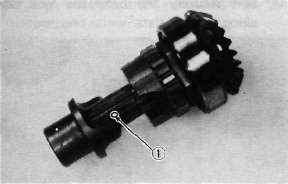
1. Oil hole
4) Install the drive damper cams, spring, spring seat, and retainers using a press and the damper compressor.
b. Middle driven gear
1) Install the new bearing housing assembly onto the driven pinion shaft.
CAUTION:
Do not press the bearing outer race. Always press the inner race with care when installing.
2) Install the drive flange and new "O-ring" onto the driven gear shaft. Apply a thread locking compound such as "LOCTITE" to the shaft threads and tighten the nut to the specified torque.
Tightening torque:
12 m-kg (87 ft-lb)
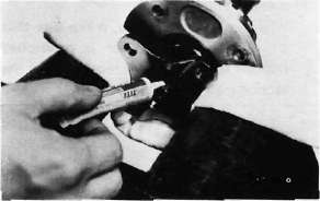
3) Stake the nut with a center punch to lock as shown.
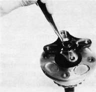
4) Install the new "O-ring" onto the bearing housing.
Upper Crankcase Reassembly
Upper Crankcase ReassemblyENGINE ASSEMBLY AND ADJUSTMENT
A. Important Information
1. Gasket and seal
All gaskets and seals should be replaced when an engine is overhauled. All gasket surfaces and oil seal lips must be cleaned.
2. Properly oil all mating engine and transmission parts and bearings during reassembly.
3. Circlip
All circlips should be inspected carefully before reassembly. Always replace piston pin clips after one use. Replace distorted circlips.
When installing a circlip, make sure that the sharp edged corner is positioned opposit to the thrust it receives. See the sectional view below.
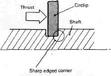
4. Lock washer/plate and cotter pin
All lock washers/plates and cotter pins must be replaced when they are removed. Lock washer/plate tab(s) should be bent over along the bolt or nut flat(s) after tightening the bolt or nut properly (see illustration).
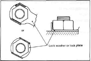
Cotter pins should be replaced after one use.
B. Engine Assembly 1. Upper crankcase
a. Install the connecting rods onto the crankshaft with the proper connecting rod bearings and apply molybedenum disulfide grease to the bolt threads. Apply torque evenly to both ends of the cap.
CAUTION:
While tightening, if a torque of 2.0 m-kg (14.5 ft-lb) or more is reached, DO NOT STOP tightening until final torque is reached.
If tightening is interrupted between 2.0 m-kg and 2.5 m-kg, loosen the nut to less than 2.0 m-kg and start again. Tighten to full torque specification without pausing.
Rod cap torque: 2.5 m-kg (18.1 ft-lb)
b- Install the proper cankshaft main bearings into the crankcase and place the crankshaft. Oil the bearings liberaly.
NOTE:
Do not forget to install the crankshaft oil seal (L.H.), blind plug (R.H.), "HY-VO" chain and cam chain on the crankshaft before installing. Also, install the chain guide into upper crankcase if removed.
c. Install the starter idle gear, shaft, stopper plate, and new lock plate. Tighten the bolt securely and bend the lock tabs along the bolt flats.
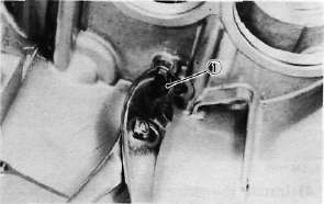
1. Lock washer
Tightening torque: 1.0 m-kg (7.2 ft-lb)
d. Put the starter clutch and sprocket assembly in the "HY-VO" chain and lay it into the crankcase.
e. Install the A.C.G. Generator shaft into the starter clutch assembly.
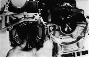
f. Install the "HY-VO" chain oil spray nozzle. The locating pin on the nozzle should be placed into the crankcase locating slot. Do not forget to install the new "O-ring" onto the nozzle.
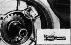
1. O-ring
g. Install the new "O-ring" onto the bearing housing and install it with the panhead screw.
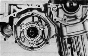
h. Install the transmission main axle assembly on the upper crankcase. Point the bearing locating pin toward the crankshaft and lav it on the case.
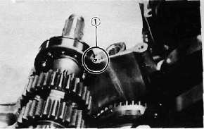
1. Bearing locating pin
i. Install the middle driven gear (without the middle drive pinion gear).
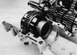
j. Install the middle driven gear shaft end bearing.
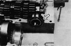
k. Install the dowel pin with "O-ring" into the crankcase.
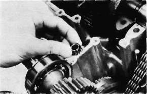
Lower Crankcase Reassembly
Lower Crankcase Reassembly2. Lower crankcase
a. Install the shift cam and secure it with the guide pin. Install the stopper plate and bolt and tighten securely.
b. Install the neutral switch.
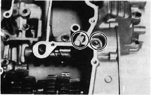
c. Install the transmission drive axle assembly into the crankcase.
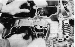
d. Install the 5th wheel gear and bearing onto the drive axle. Install the bearing cover. Be sure the "O-ring" is on the cover.
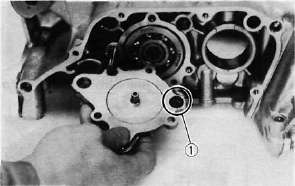
1. O-ring
e. Install the shift forks and guide bar. Each shift fork is identified by a number cast on its side. All the numbers should face the left side and numbered 1, 2, and 3 from left.
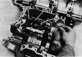
3. Crankcase assembly a. Apply Yamaha bond # 4 sealant or equivalent to the crankcase mating surface. Be very careful not to allow any sealant to come in contact with the oil gallery "O-ring" and crankshaft bearings. It is extremely important, however, that sealant be applied around the case stud holes. Apply sealant to within 2~3 mm (0.08 ~0.12 in) of the bearings.
CAUTION:
Failure to apply sealant here will result in reduced oil pressure and possible crank seizure.
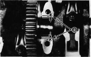
a. 2~3 mm (0.08~0.12 in) Do not apply sealant.
b. The crankcases are assembled by placing the upper case half on the bench and lowering the lower case onto it.
NOTE:
Be sure that shift fork No. 2 engages the groove in the 2nd pinion gear on the main axle.
CAUTION:
Before installing and torquing the crankcase bolts, check to make sure the transmission is functioning properly by shifting it by hand with the shift cam.

c. Start installation of the crankcase bolts with the center crankshaft area bolts. Place the two bolts without washers in the oil filter area.
d. The crankcase bolts should be torqued in proper sequence. Refer to the tightening sequence in the illustration.
LOWERCASE
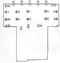
UPPERCASE
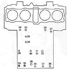
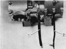
1. Engine ground wire 2. Battery ground wire
4. Oil pump and strainer cover
a. Place the oil pump drive chain on the transmission main axle.
b. Place the drive chain on the oil pump driven sprocket and install the pump on the crankcase. The "O-ring" should be installed properly.
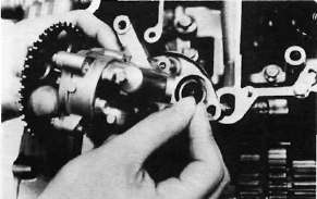
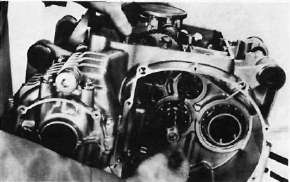
c. Install the drive chain cover on the oil pump and secure with the 2 shouldered bolts and one normal 6 mm bolt.
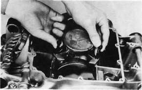
Tightening torque: 1.0m-kg(7.2ft-lb)
d. Install the strainer cover and torque the bolts to the specification.
Tightening torque: 1.0m-kg(7.2ft-lb)
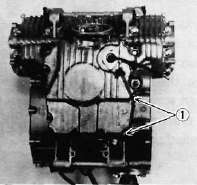
1. Wire clamps
Clutch and Shifter Reassembly
Clutch and Shifter Reassembly5. Clutch assembly
a. Install the thrust plate onto the transmission main axle.
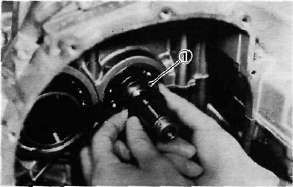
1. Thrust plate
b. Install the oil pump drive sprocket onto the main axle without the spacer collar and place the oil pump drive chain on its sprocket.
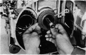
1. Oil pump drive sprocket
c. Insert the spacer collar into the oil pump drive sprocket.
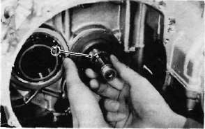
1. Spacer collar
d. Install the primary driven gear (clutch housing) without the bearing and inner spacer.
CAUTION:
Be sure that the oil pump drive gear tabs engage the clutch housing grooves on it's back or the tabs will be damaged when tightening the clutch boss securing nut.
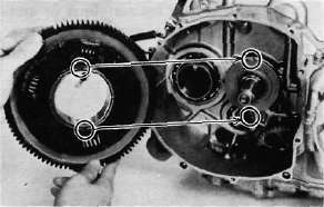
e. Installing the primary driven gear bearing and inner spacer into the clutch housing.
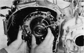
1. Driven gear bearing 2. Inner spacer
f. Install the large thrust plate and clutch boss onto the main axle.
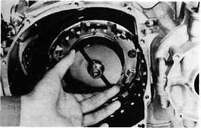
g. Install a new lock washer and nut and tighten the nut to the specified torque. Use the clutch boss holder (special tool).
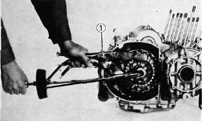
1. Clutch boss holder
Tightening torque: 7.2 m-kg (52 ft-lb)
h. Bend the lock washer tabs along the nut flats.
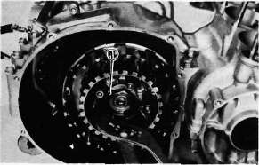
1. Lock tab
i. Install the clutch plates and friction plates alternately on the clutch boss, starting with a friction plate and ending with a friction plate.
j. Install the plate washer, thrust bearing, and clutch pull rod into the clutch pressure plate from inside.
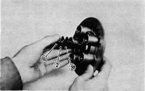
1. Pull rod 2. Thrust bearing 3. Plate washer
k. Install the pressure plate assembly onto the clutch boss.
NOTE:
Pressure plate has a dot on it which must line up with the dot on clutch boss.
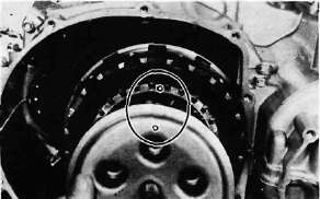
I. Install the clutch springs and screws. Tighten the screws.
Clutch screw torque: 1.0 m-kg (7.2 ft-lb)
m. Set the gear of the clutch pull rod on the pressure plate facing approximately 45° from horizontal toward the rear; set the clutch lever (if installed) on the right crankcase cover parallel to the gasket surface and install the cover to the crankcase. Do not forget to install two dowel pins.
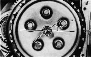
n. If the clutch lever has been removed, install the lever return spring and lever on the shaft after installing the right crankcase cover. In this case make sure that the punch mark on the lever should align with the mark on the crankcase cover when pushing the lever towards the front by hand and then install the circlip.
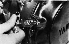
Middle Gear Reassembly
Middle Gear Reassembly6. Middle gear (installation only, refer to page 67 for the middle gear adjustment)
a. Install the middle drive gear assembly with the proper size of shim(s) and secure it with the bearing retainers and new "TORX" screws.
Tightening torque: 2.5 m-kg (18 ft-lb)
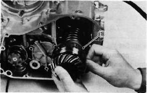
1. Shims
b. Stake the screw heads to the dents on the bearing retainers with a center punch.
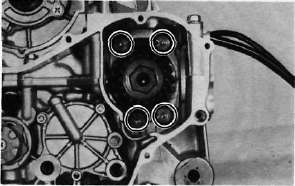
c. Install the driven gear assembly with the proper size of shims and secure it with the bolts. Apply a thread locking compound such as "LOCTITE" to the bolt threads,
Tightening torque:
2.5 m-kg (18.1 ft-lb)
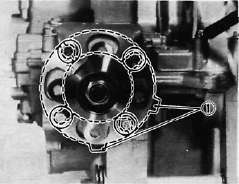
1. Shims
d. Install the middle gear case half moon seal onto the crankcase.
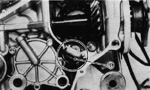
1. Seal
7. Shifter assembly
a. Install the shift shaft assembly with the stopper lever.
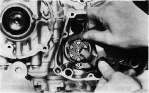
b. Install the shift lever assembly with the positioning spring is properly located on the stopper pin and the teeth should be set properly as shown.
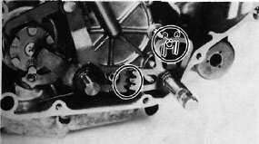
c. Install the left crankcase cover (shifter cover) using a new gasket. Make sure the wire harness clips are properly positioned.
Tightening torque: 1.0m-kg(7.2ft-lb)
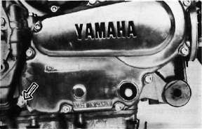
Generator, Starter and Pick-up Coil Reassembly
Generator, Starter and Pick-up Coil Reassembly8. A.C. Generator
a. Install the rotor onto the shaft and tighten the bolt using the rotor holding tool (special tool) as shown.
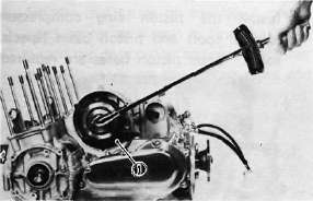
1. Rotor holding tool
Tightening torque: 5.5 m-kg (39.8 ft-lb)
b. Install the stator coil assembly onto the crankcase and align the grooves on the stator core with the bolt holes on the crankcase.
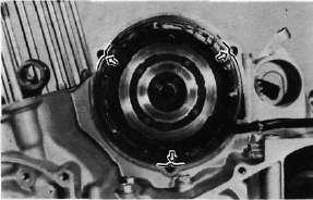
c. Install the A.C.G. cover assembly and tighten the bolts to the specification. Do not forget to install the new gasket.
Tightening torque: 1.0 m-kg (7.2 ft-lb)
9. Starter motor
a. Route the A.C.G. lead wires as shown.
b. Install the starter motor and tighten the bolts to the specification.
Tightening torque: 1.2 m-kg (8.7 ft-lb)
NOTE:
Be careful the "O-ring" is not damaged when installing the starter motor.
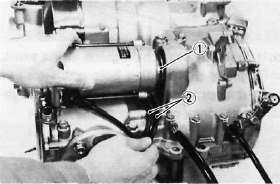
1. O-ring 2. A.C.G. lead wires
10. Pick-up coil assembly
a. Install the pick-up coil assembly onto the crankcase.
b. Install the timing plate on the crankshaft and tighten the bolt to the specification.
NOTE:
Note that there is the locating pin on the crankshaft and the corresponding slot in the timing plate which must be aligned to install the timing plate.
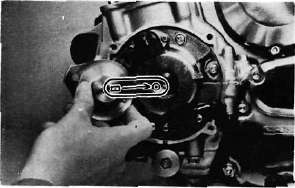
Pistons and Cylinder Reassembly
Pistons and Cylinder Reassembly11. Pistons and Cylinder a. Install the pistons on the rods. The arrow on the piston must point to the front of the engine.
NOTE:
Before installing the piston pin clips, cover the crankcase with a clean rag so you will not accidentally drop the circlip into the crankcase.
Always install new piston pin circlips.
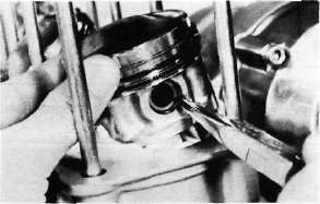
b. Install the rear chain guide on its pivot. Tighten the holding bolt until it stops and then loosen 1/4 turn and then tighten the lock nut.
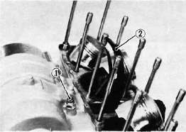
1. Holding bolt 2. Rear chain guide
c. Install the new cylinder base gasket and dowel pins. Install the new "O-rings" to the right side dowei pins.
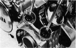
d. Set the crankshaft so that the all pistons are equal height and align the piston rings as shown.
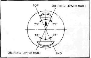
CAUTION:
Make sure the ends of the oil ring expanders are not overlapped.
NOTE:
Manufacturer's marks or numbers stamped on the rings are on the top side of the rings. Coat the pistons and rings well with oil.
e. Install the piston ring compressors (special tool) and piston bases (special tool). Four piston bases are required.
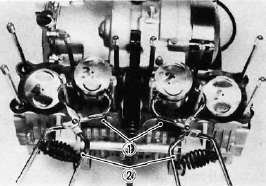
1. Piston bases 2. Piston ring compressors
f. Tie the cam chain with a piece of mechanic's wire and feed it through the chain opening. Carefully lower the cylinder onto the pistons. Remove the ring compressors and piston bases and repeat this procedure for pistons 1 and 4.
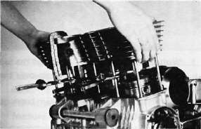
g. Install the cylinder securing nut (front side) and tighten it to the specification.
Tightening torque:
2.0 m-kg (14.5 ft-lb)
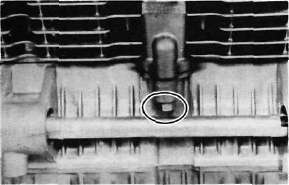
h. Set the dial gauge on the No. 1 piston head center as shown to find the No. 1 piston top dead center and check whether the "1" mark on the timing plate and stationary pointer are aligned or not. If not, loosen the pointer securing screw and adjust.
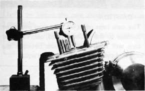
Cylinder Head and Camshaft Reassembly
Cylinder Head and Camshaft Reassembly12. Cylinder head and Cam shafts
a. Install the new cylinder head gasket. Install the dowel pins and "O-rings". Locate the cam chain cavity cylinder seal with the tabs down.
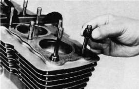
b. Install the cylinder head onto the cylinder. Pull the cam chain through the cylinder head as it is installed. Tie the cam chain so that it does not fall into the crankcase.
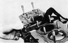
c. Place the upper cylinder head nuts and washers in place. Follow the illustration for the proper tightening sequence. Torque all nuts in two stages and final torque the upper nuts to the specification.
Tightening torque: 3.2 m-kg (23.1 ft-lb)
Don't forget the lower nuts on the front and rear of the cylinder head. Torque to the specification.
Tightening torque: 2.0 m-kg (14.5 ft-lb)
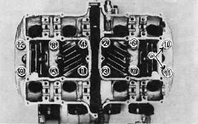
a. Copper washers
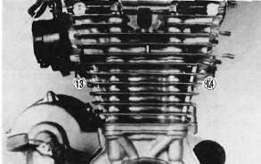
NOTE:
Tighten the nuts in two stages, 1/2 torque value and then full torque value. Also lubricate the bolt threads with the engine oil to achieve proper torque values.
d. Install the front cam chain guide being certain that it is in its holder down below.
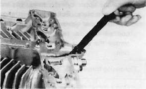
e. Rotate the engine in a counterclockwise direction until the crankcase pointer and "T" mark on the timing plate are aligned.
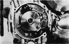
f. With the cylinders No. 1 and 4 at the top dead center, slip the cam chain over the sprocket,
g. Lubricate all cam caps and cam bearings surfaces liberally with oil.
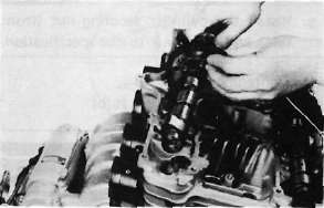
h. Place the cam caps in their proper positions. The caps are identified "1-1" through "I-3" for intake and "E-1" through "E-3" for exhaust. Install the bolts only finger tight.
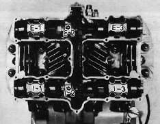
CAUTION:
The cam caps must be tightened evenly or damage to the cylinder head, cam caps and cam will result. The spaces between the
caps and cylinder head should be equal.
I. Torque the cam cap bolts in two stages and final torque to the specification.
Tightening torque: 1.0 m-kg (7.2 ft-lb)
13. Cam chain, cam sprockets and chain tensioner
a. Rotate each cam shaft until the dot on the cam is aligned with the arrow on the center cam cap.
CAUTION:
Use extreme caution when rotating the cams. Two possible dangers exist. First, the wrench may contact the head and fracture it. Or second, a valve may become bent if the cam is turned the wrong way.
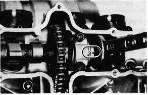
b). Carefully lift the cam chain from the exhaust cam sprocket and pull upward to remove any slack in the chain between the crankshaft and the exhaust cam sprocket. With all slack removed, place the chain back on the cam sprocket.
c). Grip each sprocket simultaneously and place them on the camshaft shoulders while continuing to keep tension on the chain from the crankshaft to the exhaust sprocket.
CAUTION:
Use only the special hardened shouldered bolts to install the cam chain sprockets to the cams.
Make sure the rollers of the cam chain are centered on both chain guides.

d. Rotate the sprockets slightly to align the bolt holes and insert one special bolt in each sprocket.
NOTE:
Tighten only finger tight at this time.
e. Install the center chain guide.
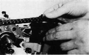
f. Rotate the crankshaft counterclockwise and align the "C" mark on the timing plate with the timing pointer.
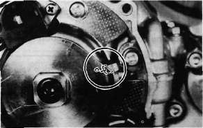
This model has been equipped the automatic cam chain tensioner. No adjustment is necessary.
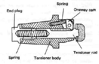
When installing this tensioner onto the cylinder proceed as follows:
1. Remove the end plug and spring from the tensioner assembly.
2. Unlock the oneway cam by pushing it with your finger and push the tensioner rod into the tensioner body until it stops.
3. Install the tensioner to the cylinder and torque the bolts to the specification.
Tightening torque: 1.0 m-kg (7.2 ft-lb)
4. Reinstall the spring and end plug with the gasket. Torque the end plug to the specification.
Tightening torque: 1.5 m-kg (11 ft-lb)
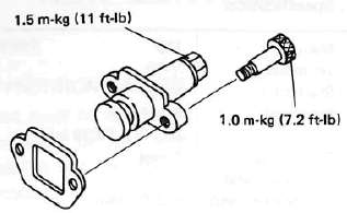
k. Rotate the crankshaft more than one full revolution and align the "T" mark on the timing plate with the timing pointer. With the crankshaft at the "T" mark, the dots on the cams should be aligned with the raised arrows on the center cam caps. If they are not aligned, disassemble the sprockets and chain tensioner and repeat above procedures.
I. Rotate the crankshaft and install the two remaining shoulder bolts into the cam sprockets. Torque all four sprocket holding bolts to the specification.
CAUTION:
Be sure to attain the specified torque value to avoid the possibility of these bolts coming loose and causing serious damage to the engine.
Tightening torque: 2.0 m-kg (14.5 ft-lb)
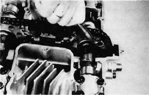
m. Adjust all valves as described in the "PERIODIC INSPECTIONS AND ADJUSTMENTS".
n. Install the cylinder head cover with a new gasket.
o. Install the left and right crankcase covers. The left crankcase cover (pickup coil cover) is required a gasket.
Middle Gear Adjustment
Middle Gear AdjustmentC. Middle Gear Servicing
1. Disassembly
Refer to page 39 for disassembly.
2. Inspection
Refer to page 52 for inspection.
3. Gear lash check
NOTE:
The middle gear lash can be checked only when the gears are installed in the crankcase.
a. Install the middle drive pinion holder (special tool) on the crankcase to hold the drive gear stationary during the lash measurement.
NOTE
Before installing the tool, loosen the holder bolt all the way out and after installation tighten this bolt as tight as necessary (finder tight is generally sufficient).
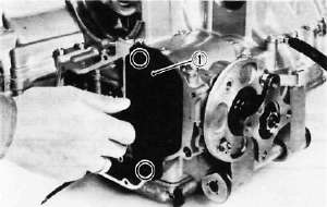
1. Middle drive pinion holder
b. Set the dial gauge to the middle drive flange as shown and gently rotate the drive flange back and forth. Note the lash measurement on the dial gauge.
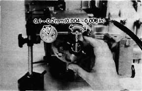
Middle gear lash: 0.1 ~ 0.2mm(0.004~ 0.008 in)
c. Check this engagement at 4 positions. Rotate the drive flange 90° each time and repeat the gear lash check.
NOTE:
If the gear lash exceeds the specified limit and adjustment is necessary, the engine or swing arm should be removed from the motorcycle.
4. Gear lash adjustment
a. Install the driven gear housing assembly into the crankcase leaving about a 2 mm (0.080 in) gap between the housing and crankcase and install the two bolts to the bearing housing 180° opposite to each other.
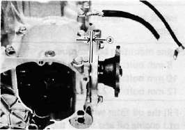
a. 2 mm (0.080 in)
b. Install the middle drive shaft holder and dial gauge (refer to "Middle gear lash check").
c. Slowly tighten the bolts alternately until the dial gauge lash measurement reaches 0.2 mm (0.008 in).
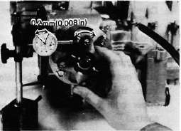
d. Measure the gap between the driven gear bearing housing flange and the crankcase with a feeler gauge. This is the shim size required.
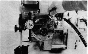
1. Feeler gauge
e. Install the proper sized shims as shown and tighten the driven gear housing to the specified torque.
Recheck the gear lash, it should be within the specification, if not readjust the shims.
Gear lash: 0.1 - 0.2 mm (0.004-0.008 in
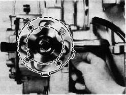
5. Drive gear positioning
NOTE:
When the following part(s) is replaced with new one(s), drive gear positioning is necessary
a. Crankcase
b. Middle gears
c. Middle gear bearing housing
a. The shim thickness necessary for the drive gear positioning can be calculated from the information found on the upper crankcase and on the drive gear shaft.
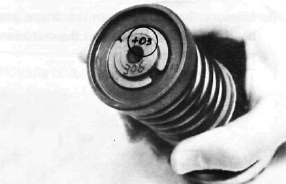
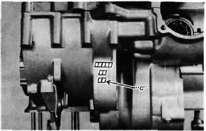
b. To find shim thickness "A" use the formula:
A = c —a — b
Where:
a= a numeral (usually a decimal number) printed on the shaft end as shown above and either added to or subtracted from the nominal size "43".
b = a bearing thickness (considered constant)
c = a numeral (usually a decimal number) found on the upper crankcase half near the main bearing selection numbers and added to the nominal size "60".
Distance "b"^ 16.94 mm
Example:
1)lf the shaft is marked +03 ...... "a" is 43.03 mm.
2) "b" is 16.94 mm.
3) If the crankcase is stamped "45" ..... "c" is 60.45 mm.
A = c — a — b
A = 60.45 - 16.94 - 43.03
A = 0.48
Then the necessary shim thickness is 0.48 mm.
c. Shim size are supplied in the following thicknesses:
0.15 mm, 0.20 mm, 0.30 mm, 0.40 mm, and 0.50 mm.
Because the shims can only be selected in 0.05 mm increments the following chart should be used when encountering last digits that are not 5 or zero (0):
|
Last digits |
Rounding |
|
0J.2 |
0 |
|
3,4,5,6,7 |
5 |
|
8,9 |
10 |
Remounting the Engine
Remounting the EngineD. Remounting Engine
Refer to page 30 for engine removal. Reverse the applicable removal steps.
CAUTION:
Always use new bolts in the drive shaft coupling.
2. Install and tighten the engine mounting bolts.
|
Engine mounting bolt torque: |
|
|
8 mm bolt: |
2.0 m-kg (14.5 ft-lb) |
|
10 mm bolt: |
4.2 m-kg (30.4 ft-lb) |
|
12 mm bolt: |
7.0 m-kg (50.6 ft-lb) |
3. Fill the oil filter with approx. 0.3 lit (0.3 qt.) engine oil and install the oil filter.
CAUTION:
The filter must be filled with the specified amount of oil to prime the oil pump of an overhauled engine.
4. Tighten engine oil drain plug, oil filter mounting bolt, and middle drain plug.
Torque:
Engine oil drain plug:
4.3 m-kg (31.0 ft-lb) Oil filter mounting bolt:
1.5 m-kg (11.0 ft-lb) Middle gear drain plug:
2.4 m-kg (17.5 ft-lb)
5. Add oil to the engine.
Engine oil: 2.9 lit (3.1 USqt.)
Chapter 4, CARBURETION
Chapter 4, CARBURETIONCHAPTER 4. CARBURETION
CARBURETOR
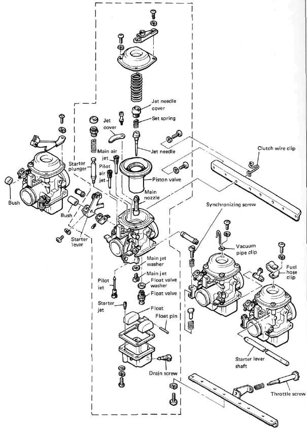
A. Section View
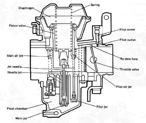
B. Specifications
|
Main jet |
#110 |
|
Jet needle |
Y-10 |
|
Needle jet |
3.2 |
|
Starter jet |
#40 |
|
Fuel level |
3±1mm(0.118±0.039in) |
|
Pilot screw |
Preset |
|
Float valve seat |
2.0 |
|
Engine idle speed |
1,050 r/m in |
CAUTION:
The pilot screw settings are adjusted for maximum performance at the factory with the use of specialized equipment. Do not attempt to change these settings. If all other engine systems are functioning correctly, any changes will decrease performance and cause increased exhaust emissions.
C. Disassembly
CAUTION:
Separation of the carburetor is not recommended. Usual disassembly for cleaning and inspection is not necessary to separate the carburetors. The carburetor body support screws are locked with a locking compound such "LOCTITE". If the carburetors are separated, misalignment will result unless reassembled on a surface plate.
1. Loosen the starter lever securing screws and remove the starter lever shaft, bushes, and levers. Note the positions of the bushes.
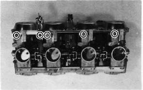
2. Remove the vacuum chamber cover and remove the spring and diaphragm (vacuum piston).
NOTE:
Note that there is the tab on the rubber diaphragm. There is the matching recess in the carburetor body for the diaphragm tab.
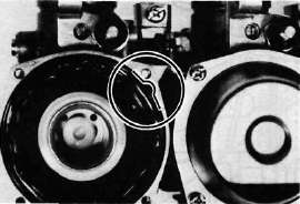
3. Remove the jet cover securing screw and remove the cover.
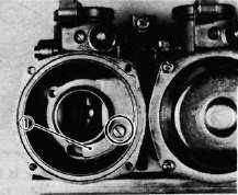
1. Jet cover
4. Remove the screws holding the float chamber cover and remove the cover. The main and pilot jets are located in the float bowl. Remove the jets if necessary.
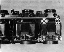
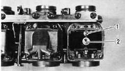
1. Pilot jet 2. Main jet
5. Pull out the float pivot pin. Remove the float assembly. Be careful to not lose the float valve under the float arm. Remove the float valve seat.
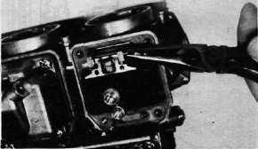
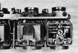
1. Float valve seat
6. Reassemble in reverse order. Pay close attention to the installation of the vacuum piston diaphragm and the location of each jet.
7. If the carburetors should be separated, care must be taken so that they are put together in place according to the following procedures:
a. Place the carburetors on a surface plate and install the lower support plate. Apply a thread locking compound such as "LOCTITE" and tighten the screws securely while holding the carburetor body.
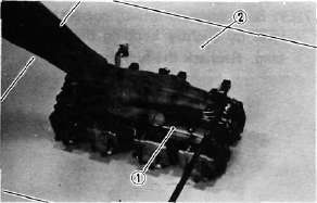
1. Lower support plate 2. Surface plate
NOTE:
When reassembling, the surface plate should be used for the proper carburetor alignment.
b. Install the upper support plate. Apply a thread locking compound such as "LOCTITE" to the support screw threads and tighten the screws securely.
D. Inspection
1. Examine the carburetor body and fuel passages. If contaminated, wash the carburetor in a petroleum-based solvent. Do not use caustic carburetor cleaning solutions. Blow out all passages and jets with compressed air.
2. Examine the condition of the floats. If the floats are damaged, they should be replaced.
3. Inspect the float needle valve and seat for wear or contamination. Replace these components as a set.
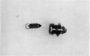
4. Inspect the vacuum piston and rubber diaphragm. If the piston is scratched or the diaphragm is torn, the assembly must be replaced.
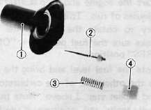
1. Vacuum piston 3. Set spring
2. Needle jet 4. Needle jet cover
5. Inspect the starter plunger for damage, If damaged, replace.
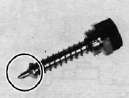
E. Adjustment
Fuel level
NOTE:
Before checking the fuel level, note the following:
1. Place the motorcycle on a level surface.
2. Adjust the motorcycle position by placing a suitable stand or a garage jack under the engine so that the carburetor is positioned vertically.
1. Connect the level gauge (special tool) or a vinyl pipe of 6 mm (0.24 in) in inside dia. to the float bowl nozzle left or right side carburetor.
2. Set the gauge as shown and loosen the drain screw.
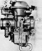
1. Level gauge 2. Drain screw
3. Start the engine and stop it after a few minutes of run. This procedure is necessary to obtain the correct fuel level. Make sure the fuel petcock is "ON" or "RES" position.
4, Note the fuel level and bring the gauge to the other end of the carburetor line and repeat step 3 above. Note the fuel level again and compare it with the previous gauge reading. They should be equal. If not, place a suitable size of wooden piece or the like under the center stand and adjust.
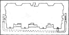
5. Check the fuel level one by one. The level should be in the specified range.
Fuel level: 3± 1 mm (0.118 ± 0.039 in) below from the carburetor mixing chamber body edge.
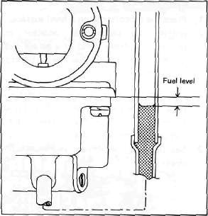
6. If the fuel level is incorrect, remove the carburetor assembly from the motorcycle and check the fuel valve(s) and float assembly(s) for damage.
7. If no damage is found, correct the fuel level by slightly bending the float arm tang. Recheck the fuel level.
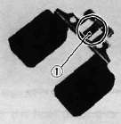
1. Float arm tang
AIR CLEANER AND CRANKCASE VENTILATION SYSTEM
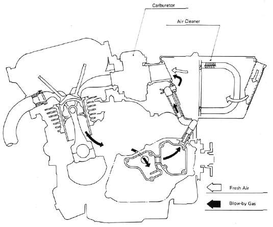
Chapter 5, CHASSIS
Chapter 5, CHASSISWheels and Brakes
Wheels and BrakesCHAPTER 5. CHASSIS
FRONT WHEEL
A. Removal
1. Place the motorcycle on the center stand.
2. Remove the cotter pin and wheel axle
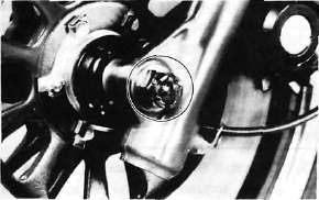
3. Remove the speedometer cable holder securing bolt.
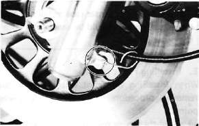
4. Loosen the pinch bolt securing the axle.
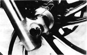
1. Pinch bolt
5. Remove the axle shaft and the front wheel. In this case, make sure the motorcycle is properly supported.
NOTE:
Do not depress the brake lever when the wheel is off the motorcycle as the brake pads will be forced to shut.
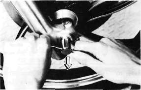
B. Front Axle Inspection
Remove any corrosion from the axle with fine emery cloth. Place the axle on a surface plate and check for bends. If bent, replace axle. Do not attempt to straighten a bent axle.
C. Front Wheel Inspection
This motorcycle is equipped with aluminum wheels designed to be compatible with either tube or tubeless tires.
Tubeless tires are installed as standard equipment.
WARNING:
Do not attempt to use tubeless tires on a wheel designed for use only with tube-type tires. Tire failure and personal injury may results from sudden deflation.
|
Tube-type Wheel > |
Tube-type Tires Only |
|
|
|
|
Tubeless-type Wheel > |
Tube-type or |
|
|
WARNING:
When using tube-type tires, be sure to install the proper tube also.
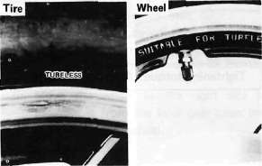
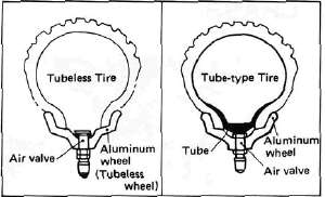
Refer to 'Tubeless Tire and Aluminum Wheel Manual" for the proper tubeless and aluminum wheel servicing.
1. Check for cracks, bends or warpage of wheels. If a wheel is deformed or cracked, it must be replaced.
2. Check wheel run-out. If the deflection exceeds the tolerance below, check the wheel bearings or replace the wheel as required.
|
Rim-run-out limits: |
|
|
Vertical |
- 2 mm (0.079 in) |
|
Lateral |
- 2 mm (0.079 in) |
3. Check wheel balance. Rotate the wheel lightly several times and observe resting position. If the wheel is not statically balanced, it will come to reset at the same position each time. Install an appropriate balance weight at lightest position (at top).
NOTE:
The wheel should be balanced with the brake disc installed.
4. After installing a tire, ride conservatively to allow the tire to seat itself on the rim properly. Failure to allow proper seating may cause tire failure resulting in damage to the motorcycle and injury to the rider.
5. After repairing or replacing a tire, check to be sure the valve stem lock nut is securely fastened. If not, torque it as specified.
Tightening torque: 0.15 m-kg (1.1 ft-lb) !
D. Replacing Wheel Bearings
If the bearings allow play in the wheel hub or if wheel does not turn smoothly, replace the bearings as follows:
1. Clean the outside of the wheel hub.
2. Drive the bearing out by pushing the spacer aside and tapping around the perimeter of the bearing inner race with a soft metal drift pin and hammer. The spacer "floats" between the bearings. Both bearings can be removed in this manner.
WARNING:
Eye protection is recommended when using striking tools.
3. To install the wheel bearing, reverse the above sequence. Use a socket that matches the outside race of the bearing as a tool to drive in the bearing.
CAUTION:
Do not strike the center race or balls of the bearing. Contact should be made only with the outer race.
E. Installing Front Wheel
When installing the front wheel, reverse the removal procedure. Note the following points:
1. Lightly grease the lips of the front wheel oil seals and the gear teeth of speedometer drive and driven gears. Use lightweight lithium soap base grease.
2. Install the speedometer cable holder securing bolt.
3. Make sure the projecting portion (torque stopper) of the speedometer housing is positioned correctly.
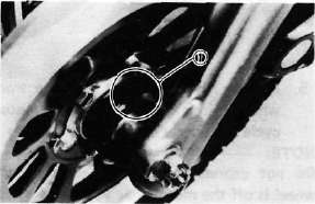
1. Torque stopper
4. Tighten the axle nut and install a new cotter pin.
Axle nut torque: 10.7 m-kg (77.4 ft-lb)
5. Install the front fender
6. Before tightening the pinch bolt, compress the front forks several times to make sure of proper fork operation.
7. Tighten the axle pinch bolt.
Axle pinch bolt torque: 2.0 m-kg (14.5 ft-lb)
REAR WHEEL
A. Removal
1. Place the motorcycle on the center stand.
2. Remove the tension bar and the brake rod from the brake shoe plate. The tension bar can be removed by removing the cotter pin and nut from the tension bar bolt. The brake rod can be removed by removing the adjuster.
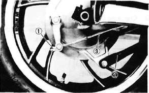
1. Adjuster 2. Tension bar 3. Brake rod
3. Remove the axle nut cotter pin and axle nut.
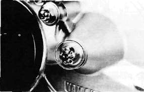
4. Loosen the rear axle pinch bolt and pull out the rear axle.
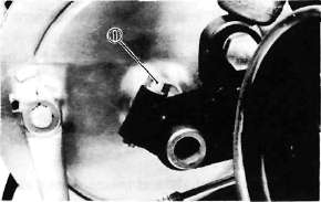
1. Pinch bolt
5. Move the wheel to the right side to separate it from the final gear cases and remove the rear wheel.
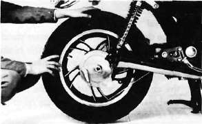
B. Checking Brake Shoe Wear
1. Measure the outside diameter at the brake shoes with slide calipers.
Front brake shoe diameter:
180 mm (7.09 in) Replacement limit:
176 mm min. (6.93 in)
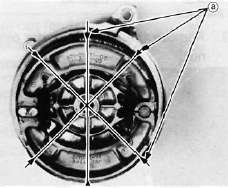
a. Measuring points
2. Remove any glazed areas from the brake shoes using coarse sand paper.
C. Brake Drum
Oil or scratches on the inner surface or the brake drum will impair braking performance or result in abnormal noises.
Remove oil by wiping with a rag soaked in lacquer thinner or solvent.
Remove scratches by lightly and evenly polishing with emery cloth.
D. Brake Shoe Plate
Remove the camshaft and grease. If the cam face is worn, replace.
NOTE:
Before removing the cam lever, put a match mark on the cam lever and camshaft to indicate their positions for easy assembly.
E. Rear Axle Inspection
(See Front Wheel, Axle Inspection Procedure.)
F. Replacing Wheel Bearings
Rear wheel bearing replacement is similar to the procedure for the front wheel.
G. Rear Wheel Inspection
(See Front Wheel, Inspection Procedures)
H. Installing Rear Wheel
1. Lightly grease lips of rear wheel oil seals.
2. Install the wheel assembly and axle.
NOTE:
When installing the rear wheel, be sure the splines on the wheel hub fit into the final gear case. Lightly apply grease to the gear teeth.
Always use a new cotter pin on the axle nut.
Tightening torque:
Axle nut: 10.7 m-kg (77.4 ft-lb) Axle pinch bolt: 0.6 m-kg (4.5 ft-lb)
FRONT BRAKE
CAUTION:
Disc brake components rarely require disassembly. Do not disassemble components unless absolutely necessary. If any hydraulic connection in the system is opened, the entire system should be disassembled, drained, cleaned and then properly filled and bled upon reassembly. Do not use solvents on brake internal components. Solvents will cause seals to swell and distort. Use only clean brake fluid for cleaning. Use care with brake fluid. Brake fluid is injurious to eyes and will damage painted surfaces and plastic parts.
A. Caliper Pad Replacement
It is not necessary to disassemble the brake caliper and brake hose to replace the brake pads. 1. Pull out the pad retaining pin while pinching the coil spring clip ends with pliers.
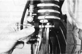
1. Coil spring clip 2. Pad retaining pin
2. Install the new brake pads. Replace the following parts if pad replacement is required.
a. Pads
b. Coil spring
c. Pin
NOTE:
Replace the pads as a set if either is found to be worn to the wear limit.
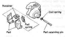
B. Caliper Disassembly
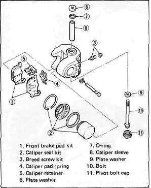
1. Remove the brake hose from the caliper. Allow the caliper assembly to drain into a container.
2. Place the open hose end into the container and pump the old fluid out of the master cylinder.
3. Remove the coil spring, pin and pads.
4. Remove the brake caliper holding bolt from the front fork.
5. Remove the retaining ring and the dust seal.
6. Carefully force the piston out of the caliper cylinder with compressed air. Never try to pry out the piston.
WARNING:
Cover the piston with a rag. Use care so that piston does not cause injury as it is expelled from the cylinder.
7. Remove the piston seal.
C. Master Cylinder Disassembly
1. Remove the brake light switch.
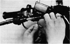
2. Remove the brake hose.
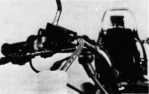
3. Remove the brake lever and spring.
4. Remove the master cylinder from the handlebar. Remove the cap and drain the remaining fluid.
5. Remove the master cylinder dust boot.
6. Remove the snap ring.

7. Remove the master cylinder cup assembly. Note that the cylinder cups are installed with the larger diameter (lips) inserted first.
D. Brake Inspection and Repair
Recommended Brake Component
Replacement Schedule: Brake pads; As required Piston seal, dust seal; Every two years Brake hoses; Every four years Brake fluid; Replace only when brakes are disassembled
1. Replace the caliper piston if it is scratched.
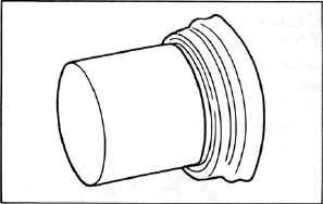
Replace any brake pad worn beyond limits. Always replace the brake pads as a set.
See Caliper Pad Replacement procedure for a listing of the parts to be replaced when pads are replaced.
Wear limit: 6.5 mm (0.26 in)
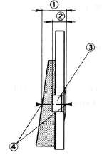
1. Pad thickness 3. Wear indicator
2. Wear limit 4. Measuring points
3. Replace piston and dust seals if damaged. Replace seals every two years.
4. Inspect master cylinder body. Replace if scratched. Clean all passages with new brake fluid.
5. Inspect the brake hoses. Replace every four years or immediately if cracked, frayed, or damaged.
6. Check for wear and deflection of disc.
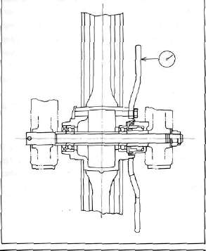
Maximum deflection: 0.15 mm (0.006 in)
Minimum disc thickness: 6.5 mm (0.26 in)
If disc is worn beyond minimum thickness or deflection exceeds specified amount, replace disc.
E. Brake Reassembly
1. Caliper reassembly
All internal parts should be cleaned in new brake fluid only. Internal parts should be lubricated with brake fluid when installed. Replace the following parts whenever a caliper is disassembled.
* Bleed screw and rubber cap
*0-ring
*Piston seal *Dust seal
* Retaining ring
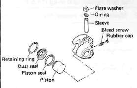
a. Install the piston seal and piston.
b. Install the pads.
2. Apply a thread locking compound such as "LOCTITE" to the pivot bolt.
3. Install the caliper assembly on the front fork.
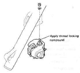
WARNING:
When installing the pivot bolt, apply it with a thread locking compound such as "LOCTITE" and tighten to the specification.
Pivot bolt torque: 2.6 m-kg (18.8 ft-lb)
4. Attach the brake hoses,
Brake hose torque: 2.6 m-kg (18.8 ft-lb)
5. Brake disc assembly
If brake disc has been removed from hub or is loose, tighten bolts. Use new locking washers and bend over locking tabs after bolts are tightened.
Disc bolt torque: 2.0 m-kg (14.5 ft-lb)
6. Master cylinder reassembly
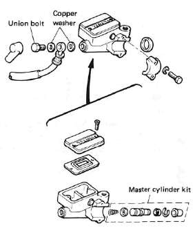
Reassemble master cylinder as shown in illustration.
Brake hose torque: (all brake union bolts) 2.6 m-kg (18.8 ft-lb)
7. Air bleeding
WARNING:
If the brake system is disassembled or if any brake hose has been loosened or removed, the brake system must be bled to remove air from the brake fluid. If the brake fluid level is very low or brake operation is incorrect, bleed the brake system. Failure to bleed the brake system properly can result in a dangerous loss of braking performance.
a. Add proper brake fluid to the reservoir. Install the diaphragm, being careful not to spill or overflow the reservoir.
b. Connect the clear plastic tube of 4.5 mm (3/16 in) inside diameter tightly to the caliper bleed screw. Put the other end of the tube into a container.
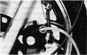
c. Slowly apply the brake lever several times. Pull in the lever. Hold the lever in "on" position. Loosen the bleed screw. Allow the lever to travel slowly toward its limit. When the limit is reached, tighten bleed screw. Then release the lever.
d. Repeat step "c" procedure until all air bubbles are removed from system.
NOTE:
If bleeding is difficult, it may be necessary to let the brake fluid system stabilize for a few hours. Repeat the bleeding procedure when the tiny bubbles in the system settle out.
Front Forks and Steering Head
Front Forks and Steering HeadFRONT FORK
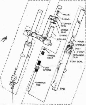
CYLINDER SECURING BOLT
Removal And Disassembly
WARNING:
Securely support the motorcycle so there is no danger of it falling over.
1. Disconnect the speedometer cable. Remove the brake caliper and the front wheel. Remove the front fender.
2. Remove the rubber cap from the top of each fork.
3. Keep the air valve open by pressing it for several seconds so that the air can be let out of the inner fork tube.
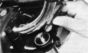
4. The spring seat and fork spring are retained by a stopper ring (spring wire circlip). It is necessary to depress the spring seat and fork spring to remove the stopper ring. Remove the stopper ring by carefully prying out one end with a small screwdriver.
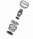
5. Place an open container under each drain hole. Remove the drain screw from each outer tube.
6. Loosen the pinch bolts on the upper and lower brackets, and remove the forks.
7. Remove the cylinder securing bolt from the bottom of the fork assembly. Hold the inner tube with the front-fork-cylinder holder. Pull the inner fork tube from the outer fork tube.
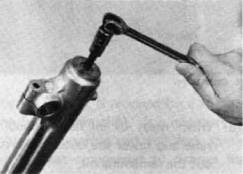
8. Remove the retaining clip from the outer fork tube, and pry out the fork seal. Be careful not to damage the fork tube surface.

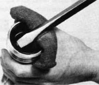
Inspection
- Examine the inner fork tube. If the tube is severely scratched or bent, it should be replaced
WARNING:
Do not attempt to straighten a bent fork tube; this may dangerously weaken the tube.
2. Inspect the outer surface of the fork seal seat in the outer fork tube. If this surface is damaged, replace the outer fork tube. If it is not damaged, replace the fork seal.
3. Check the outer fork tubes for dents. Replace the tube if it is dented.
4. Check the free length of the springs.
Fork spring free length: 467 mm (18.39 in)
5. Check the o-ring on the spring seat. If it's damaged, replace it.
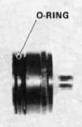
Assembly
1. Make sure all components are clean before assembly. Always install a new fork seal. Do not reuse a seal.
2. Apply oil to the fork seal, and install the fork seal by pressing it in with a large socket. Install the retaining clip.
3. Install the inner fork tube into the outer fork tube.
4. Apply Loctite® Stud N' Bearing Mount (red) to the cylinder securing bolt, and install the bolt and a copper washer into the outer fork tube. Torque the bolt to specification.
TIGHTENING TORQUE: 2.0m-kg (14.5ft-lb)
5. Reinstall the spring seat and fill the fork with air using a manual air pump.
CAUTION:
Always use a new stopper ring (spring wire circlip)
Maximum air pressure: 1.2 kg/cm1 (17 psi) Do not exceed this amount
Air pressure adjustment
1. Elevate the front wheel by placing the motorcycle on the center stand.
NOTE:
When checking and adjustment the air pressure, there should be no weight on the front end of the motorcycle.
2. Remove the rubber caps from each fork.
3. Using an air gauge, check and adjust the air pressure.
Increase air pressure — cause initial load to increase, and
absorber becomes hard.
Decrease air pressure — cause initial load to decrease, and
absorber becomes soft.
To increase:
Fill the air using a manual air pump.
To decrease:
Release the air by pushing the valve pin.
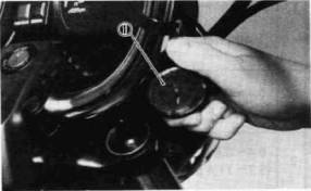
1. Air gauge
Standard air pressure: 0.4 kg/cm3 (5.7 psi)
Maximum air pressure: 1.2 kg/cm1 (17 psi)
Minimum air pressure: Zero
*Never exceed the maximum pressure, or oil seal damage may occur.
*The difference between both the left and right tubes should be 0.1 kg/cm2
(1.4 psi) or less.
3.
Install the rubber caps securely.
STEERING HEAD
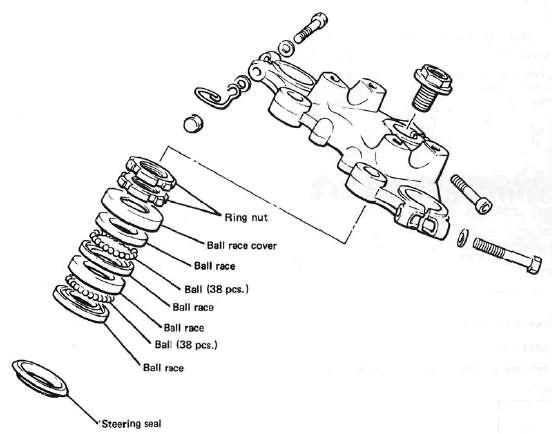
A. Adjustment
Refer to "D. Reassembly" for steering head adjustment procedure.
B. Removal
1. Remove the front wheel, front forks and handlebars.
2. Remove the front brake pipe junction.
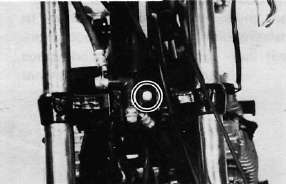
3. Loosen the steering stem (upper bracket) pinch bolt.
4. Remove the stem bolt and steering crown.
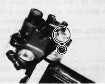
5. Remove the top fitting nut (ring nut).
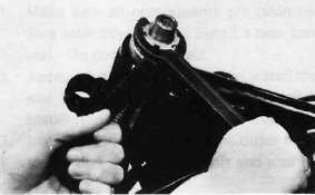
6. Support the steering stem (under bracket) and remove the bottom fitting nut (ring nut).
7. Remove the top bearing race and all of the bearing balls from the upper bearing
Ball quantity (upper and lower): 38 pieces.
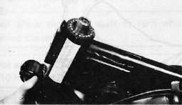
C. Inspection
1. Wash the bearings in solvent.
2. Inspect the bearings for pitting or other damage. Replace the bearings if pitted or damaged. Replace the races when bearing balls are replaced.
3. Clean and inspect the bearing races. Spin the bearings by hand. If the bearings are not smooth in their operation in the races, replace bearing balls and races.
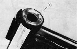
1. Bearing race
D. Reassembly
1. Grease the bearings and races with wheel bearing race.
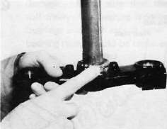
2. Install the steering stem (under bracket), bearing balls, and races.
3. Install the bottom fitting nut. Tighten it to approximately 2.5 m-kg (18 ft-lb) and loosen it approximately 1/4 turn.
4. While holding the bottom fitting nut with the ring nut wrench, tighten the top fitting nut securely.
5. Continue reassembly in the reverse of disassembly order.
6. When assembly is complete, check the steering stem by turning it from lock to lock. If there is any binding or looseness, readjust the steering stem tightness.
Pinch bolt torque: 2.0 m-kg (14.5 ft-lb)
Steering stem bolt torque 5.4 m-kg (39.1 ft-lb)
Swing Arm, Rear Shocks, Cables and Fittings
Swing Arm, Rear Shocks, Cables and FittingsSWING ARM
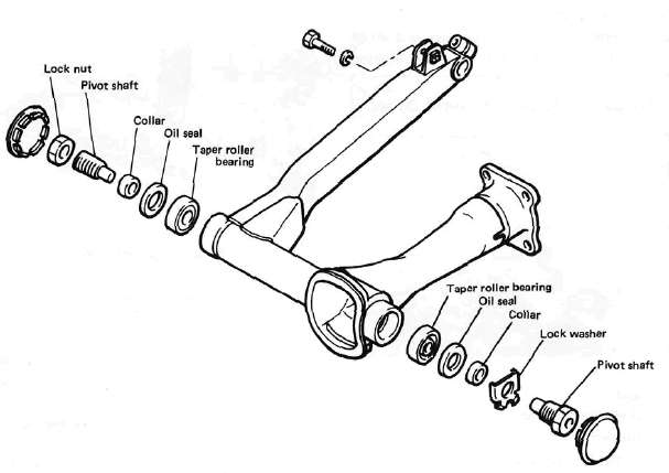
A. Inspection
1. Free play inspection
Remove the rear wheel and both shock absorbers. Grasp the swing arm and try to move it from side to side as shown. There should be no noticeable side play.
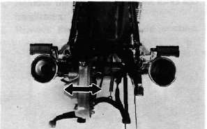
2. The swing arm is mounted on tapered bearings. Move the swing arm up and down as shown. The swing arm should move smoothly, without tightness, binding or rough spots that could indicate damaged bearings.
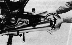
B. Adjustment
1. Remove the pivot shaft cap from the right side of the swing arm.
2. Loosen the right pivot shaft lock nut and tighten the pivot shaft (clockwise) to 0.5-0.6m-kg(43~52in-lb).
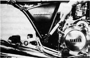
3. Tighten the pivot shaft lock nut.
NOTE:
Do not allow the pivot shaft to turn while tightening the lock nut.
Pivot shaft lock nut torque: 10m-kg (72.3ft-lb)
C. Removal
1. Remove the middle gear flange holding bolts.
2. Remove the rear wheel and shock absorbers.
3. Remove the final gear assembly.
4. Install the drive shaft puller attachment (special tool) on the side hammer bolt (special tool). Insert the 2 arms of the puller into the mouth of drive shaft housing. Tighten the 2 arms around the toothed flange of the drive shaft out of the universal joint. Pull out the drive shaft from the housing.
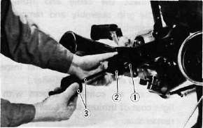
1. Drive shaft 2. Drive shaft puller 3. Slide hammer
5. Remove the swing arm pivot caps, the pivot shafts and the swing arm.
D. Inspection and Lubrication
1. Remove the oil seals and the bearings. Inspect the bearings for pitting or other damage. Make sure that the bearings roll freely. If a bearing is damaged, both bearings and both sets of inner and outer bearing races should be replaced.
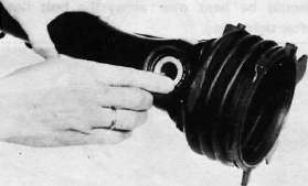
CAUTION:
Do not use compressed air to spin the bearings dry. This causes damage to the bearing surfaces.
NOTE:
When installing new bearings, grease liberally with lithium base, waterproof wheel bearing grease.
2. Always replace the grease seals when bearings are removed.
3. Examine the rubber boot for damage. Replace if damaged.
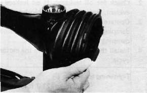
E. Installation
Installation of the swing arm can be accomplished by reversing the removal procedure. Observe adjustment procedures for obtaining equal frame/swing arm spacing.
Tightening torque: Left side pivot shaft: 10 m-kg (72.3 ft-lb) Right side pivot lock nut:
10 m-kg (72.3 ft-lb)
CAUTION:
A lock washer for left side pivot bolt must be replaced with a new one and the tab should be bent over along the bolt flat after tightening.
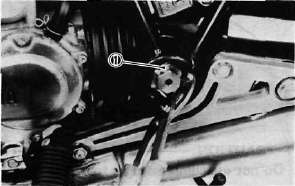
1. Lock washer
REAR SHOCK ABSORBER
A. Removal
1. Remove one (1) rear shock absorber at a time, inspect and reinstall before removing the other.
B. Inspection
1. Check the rod. If it is bent or damaged, replace the shock absorber.
2. Check for oil leakage. If oil leakage is evident, replace the shock absorber.
3. Operate shock absorber rod to check damping. There should be no noticeable damping as the shock extends.
4. Install the shock absorber on the motorcycle.
Tightening torque:
3.0 m-kg (21.7 ft-lb)
CABLE AND FITTINGS A. Cable Maintenance
NOTE:
See Maintenance and Lubrication intervals charts. Cable maintenance is primarily concerned with preventing deterioration through rust and weathering and providing proper lubrication to allow the cable to move freely within its housing. Cable removal is straight forward and uncomplicated. Removal will not be discussed within this section.
WARNING:
Cable routing is very important. For details of cable routing, see the cable routing diagrams at the end of this manual. Improperly routed or adjusted cables may make the motorcycle unsafe for operation.
1. Remove the cable.
2. Check for free movement of cable within its housing. If movement is obstruced, check for fraying or kinking of the cable strands. If damage is evident, replace the cable assembly.
3. To lubricate the cable, hold it in a vertical position. Apply lubricant to the uppermost end of cable. Leave it in the vertical position until lubricant appears at the bottom. Allow any excess to drain and reinstall the cable.
NOTE:
Choice of lubricant depends upon conditions and preferences. However, a semi-drying chain and cable lubricant will perform adequately under most conditions.
B. Throttle Maintenance
1. Remove the Phillips head screws from throttle housing assembly and separate the two halves of housing.
2. Disconnect the cable end from the throttle grip assembly and remove the grip assembly.
3. Wash all parts in a mild solvent and check all contact surfaces for burrs or other damage. (Also clean and inspect right-hand end of the handlebar.)
4. Lubricate all contact surfaces with a light coat of lithium soap base grease and reassemble.
NOTE:
Tighten the housing screws evenly to maintain an even gap between the two halves.
5. Check for smooth throttle operation and quick spring return when released and make certain that the housing does not rotate on the handlebar.
Shaft and Rear Drive
Shaft and Rear DriveSHAFT DRIVE
Refer to "CHAPTER 3". for the middle gear.
The following special tools are not available but can be constructed for the final gear disassembly and assembly:

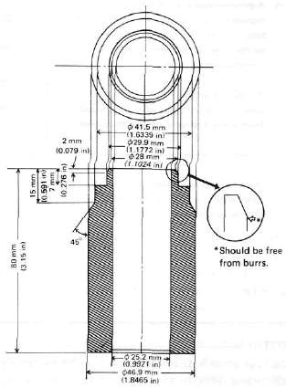
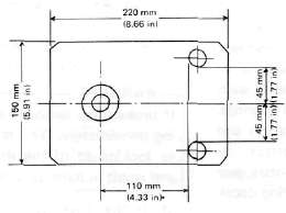
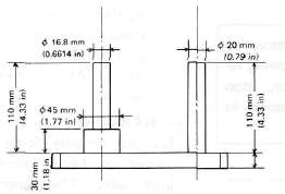
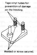
A. Troubleshooting
1. The following conditions may indicate damaged shaft drive components:
|
Symptoms |
Possible damaged areas |
|
1. A pronounced hesitation or "jerky" movement during acceleration, deceleration, or sustained speed. (This must not be confused with engine surging or transmission characteristics). 2. A "rolling rumble" noticeable at low speed; a high-pitched whine; a "clunk" from a shaft drive component or area. |
A. Damage to bearings. B. Improper gear lash. C. Gear tooth damage. D. Drive flange/universal joint bolts loose. |
|
3. A locked-up condition of the shaft drive mechanism; no power transmitted from engine to rear wheel. |
E. Broken drive-shaft. F. Disconnected flange/universal joint connection. G. Broken gear teeth. H. Seizure due to lack of lubrication. I. Small foreign object lodged between moving parts. |
NOTE:
Damage areas A, B, and C above may be extremely difficult to diagnose. The symptoms are quite subtle and difficult to distinguish from normal motorcycle operating noise. If there is reason to believe component(s) are damaged, remove component(s) for specific inspection.
2. Inspection Notes:
a. During coasting, accelerating or decelerating, the "rolling rumble" will increase with rear wheel speed, not engine or transmission gear speeds. However, such noise may also be due to wheel bearings.
b. Noise that varies with acceleration and deceleration: Following incorrect reassembly, a condition of too-little gear lash may produce a whine during deceleration.
CAUTION:
Too-little gear lash is extremely destructive to gear teeth. If a test ride following reassembly indicates this condition, stop riding immediately to minimize damage to gears.
c. A slight "thunk" must be distinguished from normal motorcycle operation. It will be most noticeable at low speed and could indicate broken gear teeth.
WARNING:
If broken gear teeth are suspected, stop riding immediately. This condition could lead to locking-up of the shaft drive assembly and result in harm to a rider.
d. If the drive flange/universal joint bolts are slightly loose, a "clunk" may be felt when slowly taking off, or when changing from slow acceleration to slow deceleration. At high speed this will result in vibration.
WARNING:
Do not continue riding a motorcycle suspected of having loose flange/universal joint bolts. The components may break, causing injury to a rider.
3. Troubleshooting Chart
Where Basic Conditions "a" and "b" above exist, consider the following Chart:
|
Elevate and spin front wheel. Feel for wheel bearing damage. |
Yes ► |
Replace wheel bearing. (See "Front wheel") |
|
No |
||
|
Check rear wheel. Feel for bearing damage. |
No ►
|
Rear wheel bearings and shaft drive bearings probably not damaged. Repeat test or remove individual components. |
|
Yes |
||
|
Remove rear wheel. Check for wheel bearing damage. |
Yes ► |
Replace rear wheel bearing. (See "Rear Wheel" section in this chapter.) |
|
No |
||
|
Remove drive shaft components. |
4. Oil Leak Inspection
If a shaft drive component is suspected of leaking oil, first thoroughly clean the entire motorcycle. The apparent location of an oil leak on a dusty motorcycle may be misleading. Dry the motorcycle and apply a leak-localizing compound or a dry-powder spray that will limit the flow of any leaking oil. Operate the motorcycle prepared in this way for the distance necessary to precisely locate the leak. There are the possibilities that a component housing may have been damaged by road debris or an accident, or a gasket or seal may be cracked or broken. However, on new or nearly new motorcycle an apparent oil leak may be the result of a rust-preventive coating or excess assembly lubrication of seals. Always clean the motorcycle and recheck the suspected location of any apparent leakage.
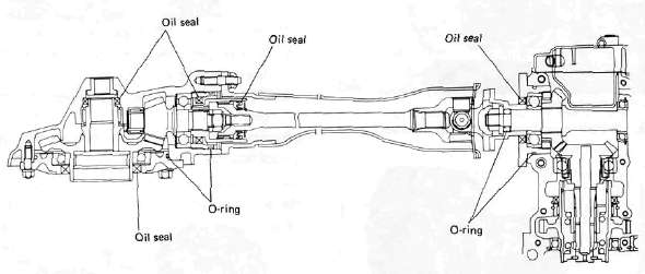
5. Checking Drained Oil
Whenever a problem is suspected in either the middle or final gear assemblies, drain and inspect the oil. Metal particles on the drain plug or in the oil could indicate a bearing seizure or other problem in the component. However, a small amount of metal particles in the oil is normal.
B. Final Gear Removal
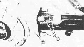
1. Remove:
• Rear axle
• Rear wheel (see "Rear Wheel" section in this chapter).
• Left shock absorber
• Nut 1
• Final gear assembly 2
2. Remove the 4 nuts holding the Final Drive unit to the swing arm.
3. Remove the final gear assembly.
C. Gear Lash Check and Adjustment
1. Secure the gear case in a vice or other support.
2. Remove one nut from the final gear case stud bolt. Install the gear holder (special tool) over the ring gear surface and stud bolt. Tighten the holder to stud bolt with a nut.
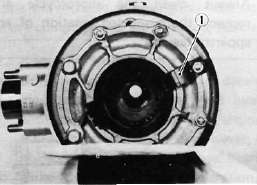
1. Final gear holding tool
3. Install the final gear lash measurement tool on the gear coupling.
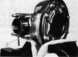
1. Gear lash measurement tool (Final gear)
4. Mount a dial gauge against the lash measurement tool at the scribed mark (60 mm, 2.36 in from the center of the shaft).
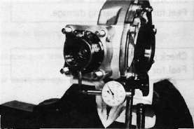
5. Use the special wrench to gently rotate the gear coupling back and forth. Note the lash measurement on the dial gauge.
Final gear lash:
When using the measurement tool: 0.25 - 0.50 mm (0.010-0.020 in) .
Actual gear lash on the final gear teeth: 0.1 ~ 0.2 mm (0.004 ~ 0.008 in).
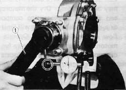
1. Middle and final gear holding tool
6. If the gear lash exceeds the specified limits, adjust as follows:
a. To reduce gear lash, increase the ring gear shim.
b. To increase gear lash, reduce ring gear shim.
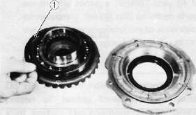
1. Ring gear shim
c. If it is necessary to increase the ring gear shim by more than 0.1 mm reduce the thrust washer thickness by 0.1 mm for each 0.1 mm of ring gear shim increase and if it is necessary to reduce shim by more than 0.1 mm, reverse above procedure.
D. Final Gear Disassembly
1. Remove the nuts and bolts holding the bearing housing.
2. Remove the ring gear assembly and thrust washer from the final gear case.
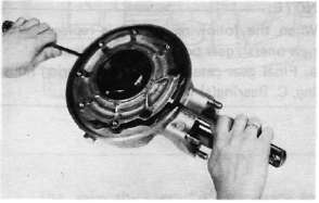
3. Remove the self-locking nut from drive pinion by using the holding tool (special tool) and remove the coupling.
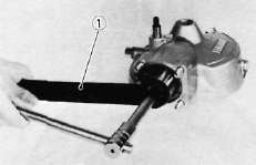
1. Middle and final gear holding tool
4. Remove the drive pinion bearing retainer with the retainer remover (special tool).
CAUTION:
The drive pinion bearing retainer nut is left hand threads. Turn the retainer nut clockwise to loosen.
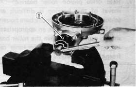
1. Drive pinion bearing retainer remover
5. Remove the drive pinion and bearing with the slide hammer and adapter (special tool).
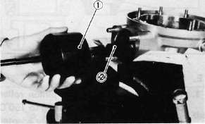
1. Slide hammer 2. Adapter
CAUTION:
This drive pinion removal should be performed only if gearing replacement is necessary. Do not re-use bearings or races after removal.
6. Remove the guide collar, oil seal, and roller bearing from the main housing by using the press tool No. 1 (special tool) and a press. Use an appropriate supports for the main housing during this operation. The roller bearing may be re-used if undamaged. Do not re-use oil seal.
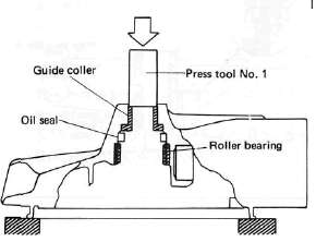
Rear drive pinion roller bearing; removal of this bearing is difficult and seldom necessary. Heat the bare housing to 150°C (302°F). Use an appropriately shaped punch to remove the roller bearing outer race. Remove the inner race from the drive pinion.
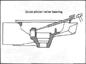
E. Final Gear Reassembly
1. Install the new rear drive pinion roller bearing. Heat the bare bearing to 150°C (302°F) and use an appropriately adapter to install the roller bearing outer race. Install the inner race onto the drive pinion.
2. Using the press tool No. 2 (special tool) and a press, install the guide collet, new oil seal, and roller bearing into the main housing in that order.
NOTE:
The removed roller bearing can be used if undamaged; however, we recommend replacement with a new one.
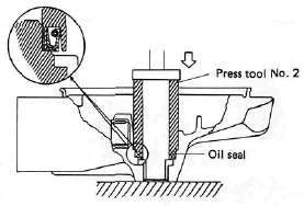
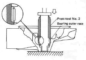
3. Final drive/ring gear positioning
NOTE:
When the following part(s) is replaced with new one(s), gear positioning is necessary:
a. Final gear case,
b. Ring gear bearing housing,
c. Bearing(s)
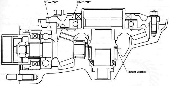
a. The shim thickness "A" necessary for the drive pinion gear positioning can be calculated from the information found on the final gear case and on the drive gear end.
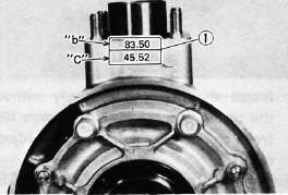
1. Size number
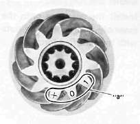
To fined shim thickness "A" use the
formula:
A = a -b
Where:
a = a numeral (usually a decimal number) on the gear near the tooth and either added to or detracted from the nominal size "84".
b = a numeral on the gear case appearing as a whole figure (ie. 83.50).
Example:
1) If the pinion gear is marked "+01"....."a" is 84.01.
2) If the gear case is marked "83.50".
A = 84.01 - 83.50 A = 0.51
Then the necessary shim thickness is 0.51mm.
Shim sizes are supplied in the following thicknesses:
0.15 mm, 0.30 mm, 0.40 mm, 0.50 mm, 0.60 mm.
Because the shims can only be selected in 0.05 mm increments the following chart should be used when encountering last digits that are not 5 or zero (0):
|
Last digits |
Rounding |
|
0,1,2 |
0 |
|
3, 4, 5, 6, 7 |
5 |
|
8,9 |
10 |
b. The shim thickness "B" necessary for the ring gear positioning can be calculated from the information found on the final gear case, ring gear, and bearing.
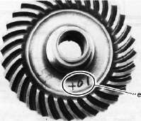
To find shim, thickness "B" use the
formula:
B = c + d-(e + f)
Where:
c= a numeral on the gear case appearing as a whole figure (ie. 45.52)
d = a numeral (usually a decimal number) on the outside of the ring gear bearing housing and added to the nominal size "3"
e= a numeral (usually a decimal number) on the inside of the ring gear and; either added to or detracted from the nominal size "35.40".
f = a bearing thickness (considered constant)
Distance "f" = 13.00 mm
Example:
1) If the gear case is marked "45.52".
2) If the ring gear bearing housing is marked "35"....."d" is 3.35.
3) If the ring gear is marked "+01" ..... "e" is 35.40 + 0.01 = 35.41.
4) "f" is 13.00.
B = c + d-(e + f)
B = 45.52 + 3.35 - (35.41 + 13.00)
B = 48.87- (48.41)
B = 0.46
Then the necessary shim thickness is 0.41 mm.
NOTE:
Use the chart for the drive pinion shim to select the ring gear shim size.
4. Install the drive pinion gear with the proper size of shim(s) and secure it with the bearing retainer nut with the drive pinion bearing retainer remover (special tool).
NOTE:
The bearing retainer nut is left hand threads; turn the nut to counterclockwise to tighten.
Tightening torque: 11 m-kg (80 ft-lb)
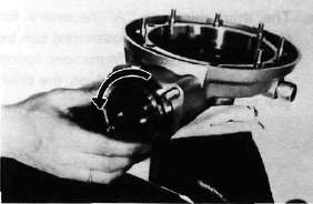
Install the ring gear assembly without the thrust washer. Adjust the gear lash (refer to "C. Gear lash check and adjustment).
Place four pieces of "PLASTIGAGE" between the originally fitted thrust washer and ring gear. Install the gear case onto the ring gear assembly and tighten the nuts and bolts with the specified torque.
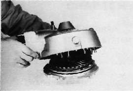
Tightening torque;
Bolt/Nut......... 2.3 m-kg
(16.6 fMb)
NOTE:
Do not turn the drive pinion/ring gear when measuring clearance with "PLASTIGAGE".
8. Remove the ring gear assembly and determine the clearance by measuring the width of the flattened "PLASTIGAGE".
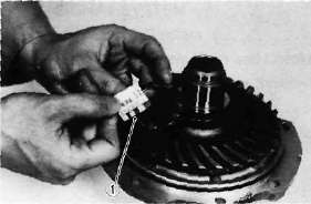
1. PLASTIGAGE
Ring gear thrust clearance. 0.1 ~ 0.2 mm
9. If the clearance exceeds the specification above, replace the thrust washer to obtain the proper clearance.
DRIVE SHAFT/JOINT
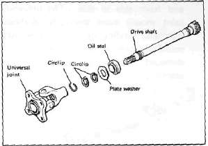
A. Removal
1. Remove the rear wheel. See "REAR WHEEL A. Removal" in this chapter.
2. Remove the final gear case assembly.
3. Remove the drive shaft. See "SWING ARM removal" in this chapter.
4. To remove the universal joint, it is necessary to remove the swing arm. Remove the universal joint assembly.
B, Inspection
1. Drive shaft
Inspect the shaft splines for wear and/or damage. If excessive, replace the drive shaft.
NOTE:
When installing the drive shaft, lubricate splines with molybdenum di-sulfide grease.
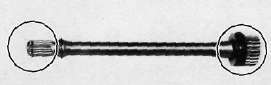
2. Universal joint
a. There should be no noticeable play in the universal joint bearings. If there is any play in the bearing, replace the universal joint assembly.
b. Move the universal joint up and down and from side to side. The universal joint should move smoothly. Without tightness, binding or rough spots that could indicate damaged bearings. If damaged, replace the universal joint assembly.
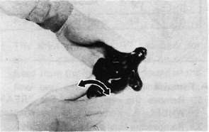
C. Reinstallation
When installing the drive shaft and the universal joint, reverse the removal procedure. Note the following points:
1. Lubricate the shaft splines with molybdenum di-sulfide grease.
2. Tighten the universal joint securing bolts and final gear case securing nuts with the specified torque:
Final gear case: 4.2 m-kg (30.4 ft-lb) Universal joint: 4.4 m-kg (31.8 ft-lb)
Chapter 6, ELECTRICAL
Chapter 6, ELECTRICALWiring Diagram
Wiring DiagramXJ650J WIRING DIAGRAM
|
COLOR CODE |
|||||
|
Dg |
Dark green |
Br |
Brown |
L/W |
Blue/White |
|
Ch |
Chocolate |
0 |
Orange |
Br/W |
Brown/White |
|
B |
Black |
L |
Blue |
Y/G |
Yellow/Green |
|
Y |
Yellow |
P |
Pink |
B/W |
Black/White |
|
G |
Green |
L/B |
: Blue/Black |
W/G |
White/Green |
|
W |
White |
R/W : Red/White |
G/Y |
Green/Yellow |
|
|
Sb |
Sky blue |
R/Y |
: Red/Yellow |
Y/R |
Yellow/Red |
|
R |
Red |
L/Y |
: Blue/Yellow |
B/Y |
Black/Yellow |
|
Gy |
Gray |
B/R |
: Black/Red |
||
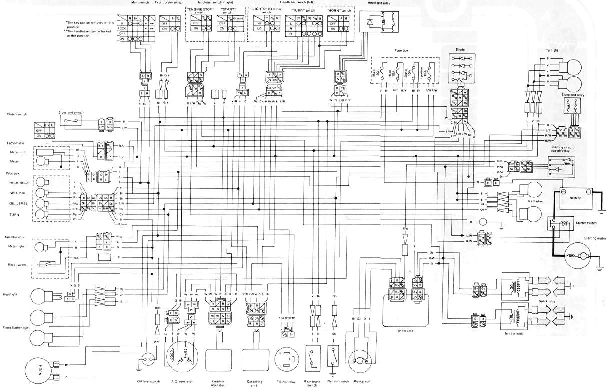
Electric Starting System
Electric Starting SystemELECTRIC STARTING SYSTEM
A. Circuit Diagram
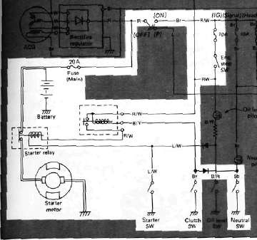
Above circuit diagram shows starter circuit in wiring diagram.
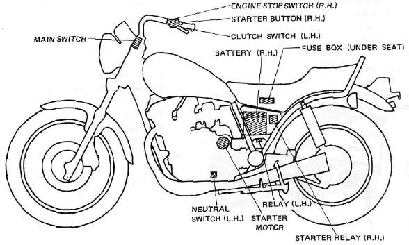
B. Starter Motor
1. Removal (see CHAPTER 3. "ENGINE DISASSEMBLY")
2. Inspection and repair
a. Check the outer surface of the commutator. If its surface is dirty, clean with # 600 grit sand paper.
b. The mica insulation between commutator segments should be 0.4 ~ 0.8 mm (0.02 ~ 0.03 in) below the segment level. If not, scrape to proper limits with appropriately shaped tool. (A hack saw blade can be ground to fit.)
NOTE:
Mica insulation of commutator must be undercut to ensure proper operation of commutator.
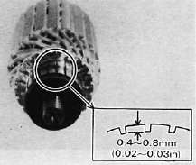
c. The starter's armature coil should be checked with an ohm meter for insulation breakdown (shorting to each other or to ground) and for continuity. Reference figure is given below.
Coil resistance: Armature coil: 0.014Ω at 20°C (68°F)
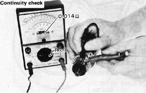
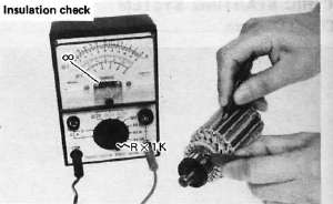
d. Check the front and rear cover bearings for damage. If damaged, the starter assembly must be replaced.
e. Check brush length. Replace brush if at, or near, limits.
Minimum brush length: 8.5 mm (0.33 in)
f. Check brush spring pressure. Compare it with a new spring. Replace the old spring if it is weak.
C. Starter Relay Switch
1. Inspection
a. Disconnect starter cable at the relay.
b. Connect pocket tester leads to the relay terminals (ohms x 1 scale).
c. Turn ignition to "ON" position, engine stop switch to "RUN" and change lever to "NEUTRAL".
d. Push the starter button. The relay should click once and the scale should read zero if it does not read zero, the relay must be replaced.
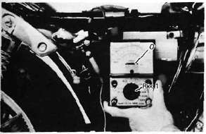
1. Battery lead wire (+)
2. Starter motor lead wire
e. If the relay does not click, check the wires from the starter button and from the battery (red/white, blue/white). Turn the ignition off. Use (ohms x 1) scale on tester. The resistance between these wires should be no more than 3.5Ω. If there is more resistance, the relay should be replaced.
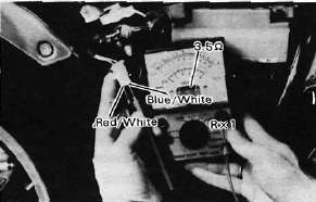
STARTING CIRCUIT CUT-OFF SYSTEM
The starting circuit cut-off system is employed. Hence, the following description.
Starting circuit operation
The starting circuit on this model consists of the starter motor, starter relay, and the starting-circuit cut-off relay. If the engine stop switch and the main switch are both on, the starter motor can operate only if:
a. The transmission is in neutral (the neutral switch is on).
or if
b. The clutch lever is pulled to the handlebar (the clutch switch is on) and the sidestand is up (the sidestand switch is on.)
The starting-circuit cut-off relay prevents the starter from operating when neither of these conditions has been met. In this instance, the starting-circuit cut-off relay is off so current cannot reach the starter motor.
When one or both of the above conditions have been met, however, the starting-circuit cut-off relay is on, and the engine can be started by pressing the starter switch.
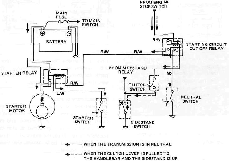
Starting-circuit cut-off relay inspection
1. Open the seat, and remove the fuel tank.
2. Remove the starting-circuit cut-off relay from the frame, and disconnect the connector.
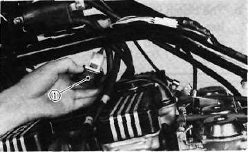
1. Starting circuit cut-off relay
3. Check the resistance of the relay coil windings with the pocket tester. If the resistance is not within specification, replace the relay.
STARTING CIRCUIT CUTOFF RELAY
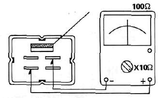
4. Check the relay function with a 12 volt battery and the pocket tester. Connect the leads as shown in the illustration. If the resistance readings do not equal those shown in the illustration, replace the relay.
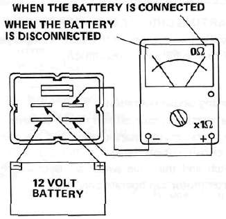
5. Check the diode in the headlight relay with the pocket tester as shown in the illustration. Replace the relay if the diode is damaged.
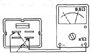
NOTE:
Only the Yamaha Pocket Tester will give a 9.5Ω reading when testing continuity. The particular characteristics of other testers will vary the continuity test readings.
Charging System
Charging SystemCHARGING SYSTEM
A. Circuit Diagram
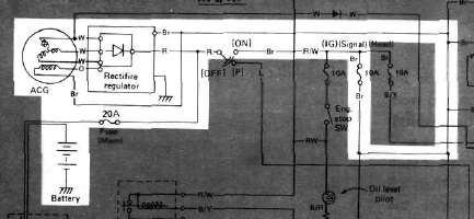
Above circuit diagram shows charging circuit in wiring diagram.
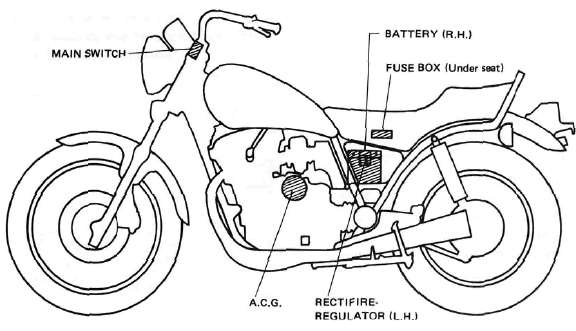
B. A.C. Generator
1. Checking method.
a. Connect D.C. voltmeter to the battery terminals.
b. Start engine.
c. Accelerate engine to approximately 2,000 r/min or more and check generated voltage.
Generated voltage: 14.5± 0.3V
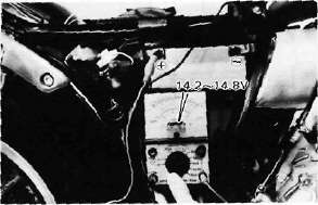
d. If the indicated voltage cannot be reached, then perform the tests in step 2.
CAUTION:
Never disconnect wires from the battery while the generator is in operation. If the battery is disconnected, the voltage across the generator terminals will increase, damaging the semiconductors.
2. Resistance test of field coil and stator coil.
Check the resistance between terminals. If resistance is out of specification, coil is broken. Check the coil connections. If the coil connections are good, then the coil is broken inside and it should be replaced.
|
Field coil resistance: |
(Green-Brown) |
|
4.0Ω ± 10% at 20°C (68°F) |
|
|
Stator coil resistance |
(White-White) |
|
0.46Ω ± 10% at 20°C (68°F) |
|
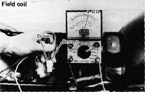
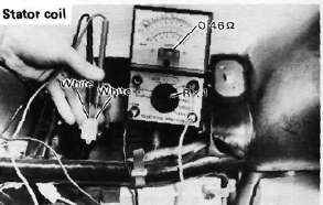
C. Voltage Regulator
The IC Voltage Regulator is a small and, normally, very reliable component. Due to its construction, it is lightweight and free from the wear and misadjustment associated with mechanical voltage regulators. If the following inspection reveals that the regulator is faulty, it cannot be adjusted and must be replaced.
1. Checking IC Voltage Regulator
a. Remove the seat.
b. Remove the left side cover.
c. Measure the specific gravity of the battery fluid. If it is less than 1.260, remove the battery and recharge until it is more than 1.260. (See page 124 for charging procedures)
d. Check the battery terminals and couplers for looseness.
e. Connect two Yamaha pocket testers to the regulator coupler as illustrated.
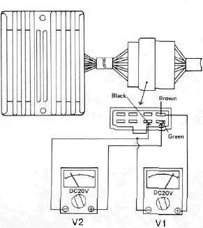
CAUTION:
Be careful not to let the tester leads short circuit when connecting them to the regulator snap connector leads.
f. Turn the main switch on. Make sure that V2 is less than 1.8V.
NOTE:
Do not turn on lights or signals.
g. Make sure that V2 gradually increases up to 9 ~ 11V when the engine is started and its revolutions go up.
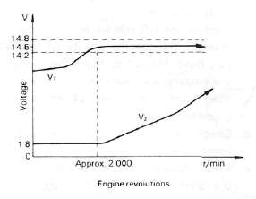
h. Make sure that Vi maintains the level of 14.2 ~ 14.8V even when engine revolutions increase.
i. If these levels are not maintained, the regulator is defective and must be replaced.
2. Checking the silicon rectifier a. Check the silicon rectifier as specified using the Yamaha pocket tester.
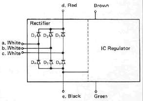
|
Checking element |
Pocket tester connecting point |
Good |
Replace (element shorted) |
Replace (element opened) |
|
|
(+) (red) |
(-) (black) |
||||
|
Di |
d |
a |
0 |
0 |
X |
|
a |
d |
X |
0 |
X |
|
|
D2 |
d |
b |
O |
0 |
X |
|
b |
d |
X |
0 |
X |
|
|
D3 |
d |
c |
0 |
0 |
X |
|
c |
d |
X |
0 |
X |
|
|
D4 |
a |
e |
0 |
0 |
X |
|
e |
a |
X |
0 |
X |
|
|
D5 |
b |
e |
0 |
0 |
X |
|
e |
b |
X |
o |
X |
|
|
D6 |
c |
e |
o |
0 |
X |
|
e |
c |
X |
0 |
X |
|
0 : Continuity
x : Discontinuity (∞)
b. Even if only one of the elements is broken, replace the entire assembly.
CAUTION:
The silicon rectifier can be damaged if subjected to overcharging. Special care should be taken to avoid a short circuit and/or incorrect connection of the positive and negative leads at the battery. Never connect the rectifier directly to the battery to make a continuity check.
Ignition System
Ignition SystemIGNITION SYSTEM A. Circuit Diagram
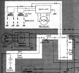
Above circuit diagram shows only ignition circuit in wiring diagram.
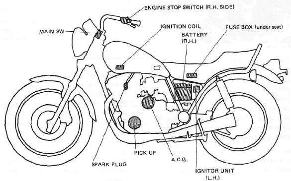
B. Description
This model is equipped with a battery operated, fully transistorized breakerless ignition system. By using magnetic pick-up coils the need for contact breaker points is eliminated. This adds to the dependability of the system by eliminating frequent cleaning and adjustment of points and ignition timing. This T.C.I. (Transistor Control Ignition) unit incorporates an automatic advance circuit controlled by signals generated by the pick-up coil. This adds to the dependability of the system by eliminating the mechanical advancer. This T.C.I, system consists of two main units; a pick-up unit and ignitor unit.
C. Operation
The T.C.I, functions on the same principle as a conventional D.C. ignition system with the exception of using magnetic pick-up coils and a transistor control box (T.C.I.) in place of contact breaker points.
1. Pick-up unit
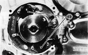
1. Pick-up coils
This unit consists of two pick-up coils and a magneto mounted on the crank-case (L.H.). When the reluctor (timing plate) projection passes the pick-up coil, the two signals are generated at the pickup coil and transmitted to the ignitor unit as a signal. The full ignition advance is determined by the width of the reluctor (timing plate) projection.
2- Ignitor unit
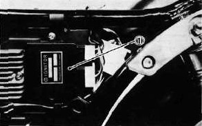
1. Ignitor unit (T.C.I. unit)
This unit has such functions of wave form, duty control, switching, electrical ignition advance, and etc. The ignition timing is advanced electrically using two signals from the pick-up coil. The duty control circuit is provided to control the on time period of the primary ignition current to reduce the electrical consumption. This unit also incorporates a protective circuit for the ignition coil. If the ignition switch is turned on and the crankshaft is not turned, the protective circuit stops current flow to the primary coil within a few seconds. When the crankshaft is turned over, the current is turned on again by the signals generated by the pick-up coils.
CAUTION:
Do not run the engine without any spark plug cap(s) in place. Due to the high secondary voltage, it is possible to damage the internal insulation of the secondary coil.
D. Troubleshooting/Inspection
1. The entire ignition system can be checked for misfire and weak spark using the Electro Tester. If the ignition system will fire across a sufficient gap, the entire ignition system can be considered good. If not, proceed with individual component tests until the problem is found.
a. Warm up engine thoroughly so that all electrical components are at operating temperature.
b. Stop the engine and connect the tester as shown.
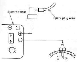
c. Start the engine and increase the spark gap until misfire occurs. (Test at various r/min between idle and red line.)
Minimum spark gap: 6 mm (0.24 in)
CAUTION:
Do not run engine in neutral above 6,000 r/min for more than 1 or 2 seconds.
2. If the ignition system should become inoperative, the following troubleshooting aids will be useful.
| Check entire ignition for connections |
---------------> Poor connection |
Correct |
|
▼ OK ▼ |
||
| Check battery for voltage and specific gravity |
---------------> Low voltage & specific gravity |
Recharge battery |
|
▼ OK ▼ |
||
| Check fuse and fuse connections | ---------------> Weak connection or open circuit |
Correct connection or replace fuse |
|
▼ OK ▼ |
||
| Check resistance of ignition coil {primary and secondary) Primary: 2.5 Ω ± 10% at 20°C (68°F) Secondary: 11KΩ ± 20% at 20°C(68 F) |
---------------> If other than specified |
Replace ignition coil |
|
▼ OK ▼ |
||
| Check pick-up coils for resistance Pick-up coil: 700 Ω ± 20% at 20°C (68°F) |
---------------> If other than specified |
Replace pick-up coil assembly |
|
▼ OK ▼ |
||
| TCI unit is faulty, replace unit |
3. Ignition coil
a. Coil spark gap test.
1) Remove the fuel tank and disconnect the ignition coil from wire harness and spark plugs.
2) Connect the Electro Tester as shown.
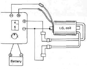
3) Connect fully charged battery to tester.
4) Turn on spark gap switch and the increase gap to maximum unless misfire occurs first.
Minimum spark gap: 6 mm (0.24 in)
b. Direct current resistance test. Use a pocket tester or equivalent ohmmeter to determine resistance and continuity of primary and secondary coil windings.
Standard value: Primary coil resistance:
2.5Ω ± 10% at 20°C (68°F)
Secondary coil resistance:
11 KΩ ± 20% at 20% (68°F)
Primary coil check
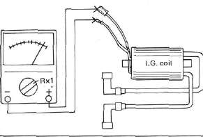
Secondary coil check
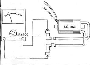
4. Spark plug
The life of a spark plug and its discoloring vary according to the habits of the rider. At each periodic inspection, replace burned or fouled plugs with new ones of the specified type. It is actually economical to install new plugs often since it will tend to keep the engine in good condition and prevent excessive fuel consumption.
a. Inspection
1) Inspect and clean the spark plug every 4,000 km (2,500 mi) and replace after initial 13,000 km (8,000 mi).
2) Clean the electrodes of carbon and adjust the electrode gap to the specification.
b. Installation
Be sure to use the proper reach, type and electrode gap plug(s) as a replacement to avoid overheating, fouling or piston damage.
Type: BP7ES (NGK) or W22EP (ND)
Electrode gap: 0.7 - 0.8 mm (0.028 - 0.031 in)
Tightening torque: 2.0 m-kg (14.5 ft-lb)
Lighting System
Lighting SystemLIGHTING SYSTEM
A. Circuit Diagram
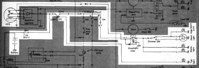
Above circuit diagram shows only lighting circuit in wiring diagram.
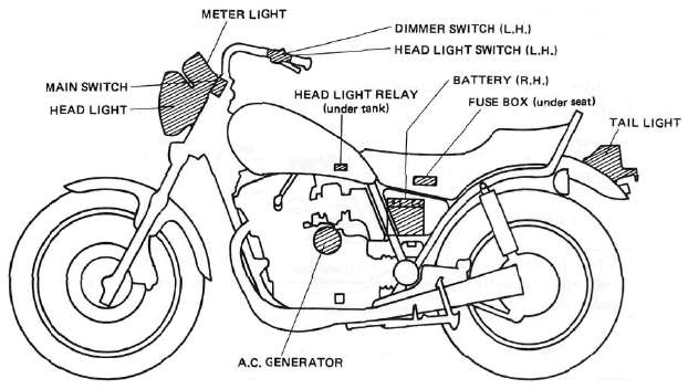
B. Lighting Tests and Checks
The battery provides power for operation of the headlight, taillight, and meter lights. If none of the above operates, always check battery voltage before proceeding further. Low battery voltage indicates either a faulty battery, low battery water, or a defective charging system. See page 113 "CHARGING SYSTEM" for checks of battery and charging system. Also check fuse condition. Replace any "open" fuses. There are individual fuses for various circuits (see complete Circuit Diagram).
NOTE:
Check the headlight bulb first before performing the following check.
1. Headlight check
NOTE:
When the engine is started, the headlight and meter lights come on automatically and the lights stay on until the main switch is turned to "OFF" even if the engine stalls.
|
HEADLIGHT DOES NOT COME ON WHEN ENGINE IS RUNNING |
||
|
Check for voltage on "W" wire to safety relay |
-----------> |
Check AC generator, diode, or wiring circuit |
|
▼ ▼ |
||
|
Check for battery voltage (12V) on "R/Y" wire to headlight relay |
-----------> No voltage |
Check fuse "Head or wiring circuit |
|
▼ Voltage OK ▼ |
||
|
Check for battery voltage (12V) on "L/B" wire from headlight relay |
-----------> No voltage |
Replace headlight relay |
|
HIGH BEAM AND/OR LOW BEAM DO NOT LIGHT |
||
|
Check for battery voltage at dimmer switch terminal |
-----------> |
Dimmer switch defective |
|
▼ Voltage OK ▼ |
||
|
Check for battery voltage at headlight high beam or low beam terminal |
-----------> |
Open or poor connection between headlight and dimmer switch terminal |
|
▼ Voltage OK ▼ |
||
|
Poor ground or poor connection of headlight wiring |
||
2. Taillight does not work:
a. Check bulbb
b. Check for 12V on blue wire.
c. Check for ground on black wire to tail/brake light and/or license light assembly.
Signals
SignalsSIGNAL SYSTEM
A. Circuit Diagram
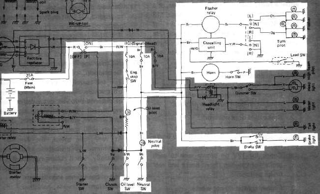
Above circuit diagram shows only signal circuit in wiring diagram.
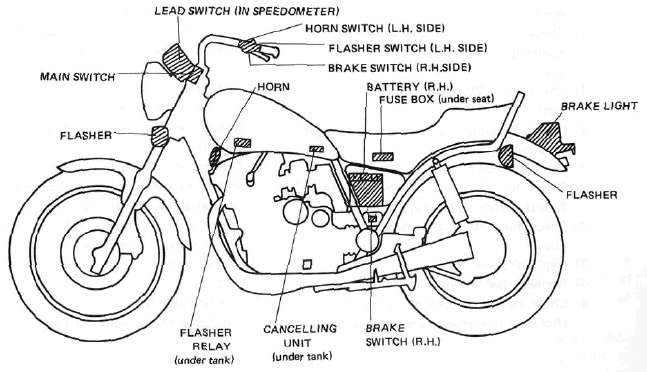
B. Signal System Tests and Checks
The battery provides power for operation of the horn, brake light, indicator lights and flasher light. If none of the above operates, always check battery voltage before proceeding further. Low battery voltage indicates either a faulty battery, low battery water, or a defective charging system. See page 113 "CHARGING SYSTEM" for checks of battery and charging system. Also check fuse condition. Replace any "open" fuses. There are individual fuses for various circuits (see complete Circuit Diagram).
1. Horn does not work:
a. Check for 12V on brown wire to horn.
b. Check for good grounding of horn (pink wire) when horn button is pressed.
2. Brake light does not work:
a. Check bulb.
b. Check for 12V on yellow wire to brake light.
c. Check for 12V on brown wire to each brake light switch (front brake and rear brake switches).
3. Flasher light(s) do not work:
a. Check bulb.
b. Right circuit:
1) Check for 12V on dark green wire to light.
2) Check for ground on black wire to light assembly.
c. Left circuit:
1) Check for 12V on dark brown wire to light.
2) Check for ground on black wire to light assembly.
d. Right and left circuits do not work:
1) Check for 12V on brown/white wire to flasher switch on left handlebar.
2) Check for 12V on brown wire to flasher relay.
3) Replace flasher relay.
4) Replace flasher switch.
e. Check flasher self-canceling system. (Refer to flasher self-canceling system.)
4. Neutral light does not work:
a. Check bulb.
b. Check for 12V on sky blue wire to neutral switch.
c. Replace neutral switch.
6. Oil level warning light does not work:
a. Connect oil level switch (black/red wire) to ground. If light comes on, check for proper oil level.
b. If oil level is correct, replace oil level switch.
C. Self-Canceling Flasher System
1. Description:
The self-canceling flasher system turns off the turn signal after a period of time or distance involved in turning or changing lanes. Generally, the signal will cancel after either 10 seconds, or 150 meters (490 feet), whichever is greater. At very low speed, the function is determined by distance; at high speed, especially when changing speeds the canceling determination is a combination of both times and distance.
2. Operation:
The handlebar switch has three positions: L (left), OFF, and R (right). The switch lever will return to the "OFF" position after being pushed to L or R, but the signal will function. By pushing the lever in, the signal may be cancelled manually.
3. Inspection
If the flasher self-canceling system should become inoperative, proceed as follows:
a. Pull of the 6-pin connector from the flasher canceling unit, and operate the handlebar switch, if the signal operates normally in L, R, and OFF, the following are in good condition.
1) Flasher unit
2) Bulb
3) Lighting circuit
4) Handlebar switch light circuit
If (1) through (4) are in good condition, the following may be faulty:
1) Flasher canceling unit.
2) Handlebar switch reset circuit.
3) Speedometer sensor circuit.
b. Pull off the 6-pin connector from the flasher canceling unit, and connect a tester (ohms x 100 range) across the white/green and the black lead wires on the wire harness side. Turn the speedometer shaft. If the tester needle swing back and forth between 0 and ∞, the speedometer sensor circuit is in good condition. If not, the sensor to wire harness may be inoperative.
c. Pull the 6-pin connector from the flasher canceling unit. Check if there is continuity between the yellow/red lead wire on the wire harness side and the chassis.
Flasher switch OFF: ∞
Flasher switch L or R: 0 ohms
If the tester needle does not swing as indicated above, check the handlebar switch circuit and wire harness.
d. If no defect is found with the above three check-ups and the flasher canceling system is still inoperative, replace the flasher canceling unit.
e. If the signal flashes only when the handlebar switch lever is turned to L or R and it turns off immediately when the handlebar switch lever returns to center, replace the flasher canceling unit.
D. Switches
Switches may be checked for continuity with a pocket tester on the "ohm x 1" position. 1. Main switch
|
Switch Position |
Wire Color |
||
|
R |
Br |
L/Y |
|
|
ON |
0---- |
--0-- |
----0 |
|
OFF |
|
|
|
|
LOCK |
|
|
|
|
P (parking) |
0---- |
------ | ----0 |
2. "ENGINE STOP" Switch
|
Switch |
Wire Color |
|
|
Position |
R/W |
R/W |
|
RUN |
0---- |
----0 |
|
OFF |
|
|
3. "START" switch
|
Button Position |
Wire Color |
|
|
L/W |
Ground |
|
|
PUSH |
O----- |
----O |
|
OFF |
|
|
4. "LIGHTS" (Dimmer) switch
|
Switch Position |
Wire Color |
|||||
|
Y |
L/Y |
G |
G |
L/G |
Y/B |
|
|
HI |
0--- | --O |
|
0--- |
--O |
|
|
LO |
|
0--- |
--O |
|
O---- |
--O |
5. "TURN" switch
|
Switch Position |
Wire Color |
||||
|
Ch |
Br/W |
Dg |
Y/n |
Ground |
|
|
L |
0--- |
--O |
|
0--- |
--O |
|
L > N |
0--- |
--O |
|
|
|
|
N > Push |
|
|
|
|
|
|
R > N |
|
O--- |
--O |
|
|
|
R |
|
O--- |
--O |
0--- |
--O |
6. "HORN" Switch
|
Button Position |
Wire Color |
|
|
P |
Ground |
|
|
PUSH |
O--- |
------O |
|
OFF |
|
|
E. Battery
1. Checking
If the battery shows the following defects, it should be replaced.
a. The battery voltage will not rise to a specific value or no gassing occurs in any cell even after many hours of charging.
b. Sulfation of one or more cells is indicated by the plates turning white or an accumulation of material in the bottom of the cell.
c. Specific gravity readings after a long slow charge indicate a cell to be lower than any others.
d. Warpage or buckling of plates or insulators is evident.
WARNING:
Battery fluid is poisonous and dangerous, causing severe burns, etc. Contains sulfuric acid. Avoid contact with skin, eyes or clothing.
Antidote:
EXTERNAL-FLUSH with water.
INTERNAL-Drink large quantities of water or milk. Follow with milk of magnesia, beaten egg or vegetable oil. Call physician immediately.
Eyes: Flush with water for 15 minutes and get prompt medical attention.
Batteries produce explosive gases. Keep sparks, flame, cigarettes, etc., away. Ventilate when charging or using in enclosed space. Always shield eyes when working near batteries.
KEEP OUT OF REACH OF CHILDREN.
2. The service life of a battery is usually 2 to 3 years, but lack of care as described below will shorten the life of the battery.
a. Negligence in keeping battery topped off with distilled water.
b. Battery being left discharged.
c. Over-charging with heavy charge.
d. Freezing.
e. Filling with water or sulfuric acid containing impurities.
f. Improper charging voltage or current on new battery.
3. If the motorcycle is not to be used for a long time, remove the battery and have it stored. The following instructions should be observed:
a. Recharge the battery periodically.
b. Store the battery in a cool, dry place.
c. Recharge the battery before reinstallation.
|
Battery |
12N12A-4A-1 |
|
Electrolyte |
Specific gravity: 1.280 |
|
Initial charging current |
1.2 amp for 10 hours (new battery) |
|
Recharging current |
10 hours (or until specific gravity reaches 1.280) |
|
Refill fluid |
Distilled water (to maximum level line) |
|
Refill period |
Check once per month (or more often, required) |
Sidestand Relay and Switch
Sidestand Relay and SwitchSidestand relay operation
The sidestand relay operates by shorting the TCI control current. When the sidestand is down, the sidestand relay is closed, and the TCI control current is grounded through the sidestand relay. Thus, the engine will not run with the sidestand down unless the transmission is in neutral.
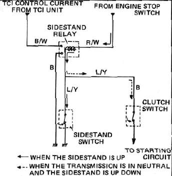
Sidestand relay inspection
1. Open the seat, and remove the fuel tank,
2. Remove the sidestand relay from the frame, and disconnect the connector.
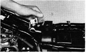
1. Sidestand relay
3. Check the resistance of the relay coil windings with the pocket tester. If the resistance is not within specification, replace the relay.
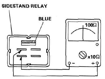
4. Check the relay contact breaker points with the pocket tester and a 12 volt battery. Connect the leads as shown in the illustration. If the resistance readings do not equal those shown in the illustration, replace the relay.
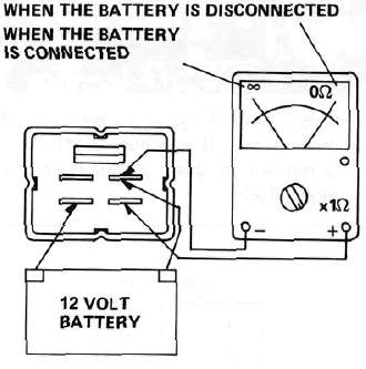
Sidestand switch inspection
1. Remove the seat and side cover (R). Disconnect the connector from the wiring harness.
2. Connect the pocket tester leads as shown, and set the tester selector to ohm x 1. When the sidestand is up, the tester should read zero ohms. When the sidestand is down, the tester should read infinity.
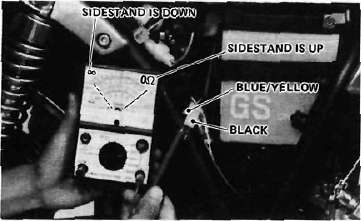
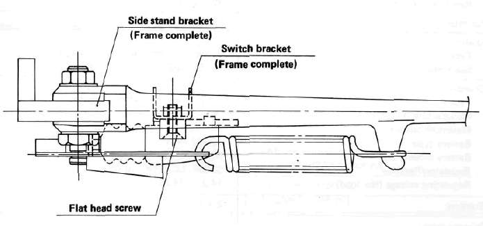
Diode Block
Diode BlockDiode block
1. Remove the headlight, and remove the diode block from the wiring harness.
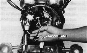
2. Check each diode and resistor in the diode block. If any diode in the resistor is not within specification, replace the diode block.
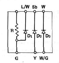
|
Checking element |
Pocket tester connecting point |
Good |
Replace (element shorted) |
Replace (element opened) |
|
|
(+) (red) |
(black) |
||||
|
R |
B/R |
G |
8.2Ω |
0 Ω |
∞ |
|
Di |
L/W |
G |
O |
o |
X |
|
G |
L/W |
X |
o |
X |
|
|
D2 |
Sb |
Y |
O |
o |
X |
|
V |
Sb |
X |
o |
X |
|
|
D3 |
w |
W/G |
O |
o |
X |
|
W/G |
W |
X |
o |
X |
|
O ; Continuity
x ; Discontinuity (∞)
Chapter 7, Appendices
Chapter 7, AppendicesSpecifications
SpecificationsSPECIFICATIONS
General Specifications
|
|
XJ650J |
|
Basic color Dimensions: Overall length Overall width Overall height Seat height Wheelbase Minimum ground clearance Caster (steering head angle) Trail |
Black Red or Frost Silver
2,165 mm (85.2 in) 860 mm (33.9 in) 1,180 mm (46.5 in) 750 mm (29.5 in) 1,445 mm (56.9 in) 150 mm ( 5.9 in) 29° 124 mm (4.88 in) |
|
Weight: Net |
203 kg (447 lb) |
|
Engine: Type Bore x stroke x cylinders Displacement Compression ratio |
D.O.H.C. air-cooled, gasoline 63.0 x 52.4 mm x 4 (2.480 x 2.063 in x 4) 653 cc (39.85 cu. in) 9.2 : 1 |
|
Lubrication: Lubrication system Delivery pump type |
Pressure lubricated, wet sump Trochoid |
|
Carburetion: Manufacture Type Rated venturi size |
HITACHI HSC32, constant velocity 32 mm (1.26 in) |
|
Air filter: |
Dry type element |
|
Ignition: |
Battery ignition (Full transistor ignition) |
|
Charging: Type Manufacture, I.D. No. Maximum output Battery type Battery dimensions Regulator/Rectifier Regulating voltage (No. load) |
Three-phase, regulated alternator HITACHI, LD119-08 14V 19A 12N12A-4A 80 x 160 x 134 mm (3.15 x 6.30 x 5.28 in) S8534, I.C. type, full wave 14.2 - 14.8V |
|
Starting: |
Electric starter |
|
Primary drive: Type Teeth, ratio |
Spur gear 97/58 1.672 |
|
Clutch: |
Wet, multiple disc |
|
Transmission: Type |
Constant mesh, 5-speed drum shifter |
|
|
XJ650G |
|
Teeth, ratio 1st 2nd 3rd 4th 5th |
35/16 2.187 30/20 1.500 30/26 1.152 28/30 0.933 26/32 0.812 |
|
Secondary drive: |
|
|
Type Transmission output: Middle gear case: Final gear case: |
Shaft drive Spur gear, 49/36, 1.361 1 Bevel gear, 19/18, 1.055 Bevel gear, 32/11,2.909 |
|
Chassis: |
|
|
Frame Suspension: Tires: Rear Brakes: Fuel tank: Wheels: |
Tubular steel double cradle Telescopic fork 150 mm (5.91 in) 3.25H19-4PR,Tubeless 130/90-16 67H, Tubeless
Single hydraulic disc
13 Lit (3.4 US. gal)
MT1.85 x 19, Cast Aluminum |
Maintenance Specifications
1. Engine
|
Engine oil capacity: Total amount Oil and filter change Oil change Recommended lubricant: If temperature does not go below 5"C (40 F) If temperature does not go above 15~C (60 F) |
3,500 cc (3.7 US. qt) 2,650 cc (2.8 US. qt) 2,350 cc (2.5 US. qt)
SAE 20W/40SE motor oil SAE 10W/30SE motor oil |
|
Cranking pressure (at seal level): Maximum difference between cylinders: |
11 kg/cm2 (156 psi) 1 kg/cm2 (14 psi) |
Camshafts:
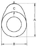
|
Dimensions |
Standard size |
Wear limit |
|
|
Intake |
A B C |
36.80 mm (1.449 in) 28.0 mm (1.102 in) 8.50 mm (0.335 in) |
36.65 mm (1.443 in) 27.85 mm (1.096 in) --------------------- |
|
Exhaust |
A B C |
35.80 mm (1.449 in) 28.0 mm (1.102 in) 7.8 mm (0.307 in) |
35.65 mm (1.404 in) 27.85 mm (1.096 in) --------------------- |
Camshaft bearing surface diameter:
24.967 - 24.980 mm (0.9830 ~ 0.9835 in)
Camshaft-to-cap clearance:
Standard 0.020- 0.054 mm (0.0008-0.0021 in)
Maximum 0.160 mm (0.006 in)
Camshaft runout limit 0.1 mm (0.004 in)
Valves:
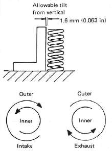
|
|
Inner |
Outer |
|
Free length |
35.9 mm (1.413 in) |
39.5 mm (1.555 in) |
|
Spring rate |
2.36 kg/mm (132.2 lb/in) |
4.58 kg/mm (256.5 lb/in) |
|
Installed length (valve closed) |
31.0 mm (1.220 in) |
34.0 mm (1.339 in) |
|
Installed pressure (valve closed) |
9.0 kg (19.8 lb) |
19.1 kg (42.1 lb) |
|
Compressed length (valve open) |
IN: 22.8 mm (0.898 in) |
IN: 25.8mm(1.016 in) EX:26.5mm(1.043 in) |
|
Wire diameter |
2.8 mm (0.110 in) |
3.9 mm (0.154 in) |
|
Number of windings |
7.75 |
6.1 |
|
Winding O.D. |
20.6 +°*3 mm (0.811**012 in) |
29.4_° mm (1.157^0°012 in) |
Valve stem run-out maximum: 0.03 mm (0.0012 in)
Valve seat width standard/maximum : 1.0 mm (0.039 in)/2.0 mm (0.080 in)
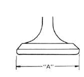
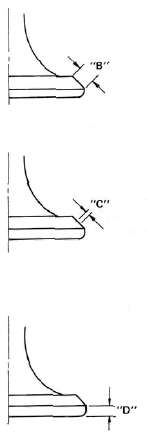
INTAKE
|
Clearance (Cold engine) |
0.11 -0.15 mm (0.004- 0.006 in) |
|
"A" head diameter |
33 ± 0.1 mm (1.2992 ± 0.0039 in) |
|
"B" face width |
2.3 mm (0.0906 in) |
|
"C" seat width |
1.0 ± 0.1 mm (0.0394 ± 0.0039 in) |
|
"D" margin thickness (minimum) |
1.2 ±0.2 mm (0.0472 ±0.0079 in) |
|
Stem diameter (O.D.) |
-,-0.010 7-0.025 mm tn 07RR -0.0004 . . (0>2756 -0.0010 m) |
|
Guide diameter (|.D.) |
-,+0.012 ' q mm (0.2756 +°000B in) |
|
Stem-to-guide clearance |
0.010 ~0.037mm (0.0004 ~ 0.0015 in) |
EXHAUST
|
Clearance (Cold engine) |
0.16~ 0.20mm (0.006-0.008 in) |
|
"A" head diameter |
28 ± 0.1 mm (1.2205 ±0.0039 in) |
|
"B"face width |
2.3 mm (0.0905 in) |
|
"C" seal width |
1.0 ± 0.1 mm (0.0394 ± 0.0039 in) |
|
"D" margin thickness (minimum) |
1.0 ±0.2 mm (0.0392 ± 0.0079 in) |
|
Stem diameter (O.D.) |
7 -0.025 mm (0.2756 -0.0010 in) |
|
Guide diameter (I.D.) |
7 +0.012 mm (0.2756 -0.0005 in) |
|
Stem-to-guide clearance |
0.025 ~ 0.052 mm |
|
Cylinder and piston: |
|
|
Cylinder material Cylinder liner Bore size: Cylinder taper limit Cylinder out-of-round limit Piston clearance: maximum Piston weight (include rings, pin and clips) |
Aluminum alloy Pressed in; special cast iron
63.00 mm (2.4803 in) 0.05 mm (0.0020 in) 0.01 mm (0.0004 in)
0.030 ~ 0.050 mm 213 g (7.520oz) |
|
Piston rings: |
Top |
2nd |
Oil |
|
Design |
Barrel |
Taper |
Expander |
|
End gap (installed): standard |
0.15-0.35 mm (0.0059 ~ 0.0138 in) |
0.15-0.35 mm (0.0059 ~ 0.0138 in) |
0.3-0.9 mm (0.0118 -0.035 in) |
|
limit |
1.0 mm (0.0394 in) |
1.0 mm (0.0394 in) |
1.5 mm (0.0591 in) |
|
Side clearance: standard |
0.03-0.07 mm (0.0012 ~ 0.0028 in) |
0.02-0.06 mm (0.008 -0.0024 in) |
----- |
|
limit |
0.15 mm (0.0059 in) |
0.15 mm (0.0059 in) |
—-- |
|
Crankshaft: |
|
|
Crank journal/bearing oil clearance Main journal run-out (maximum) |
0.040-0.064 mm (0.0016-0.0025 in) 0.040 mm (0.0016 in) |
|
Connecting rods |
|
|
Weight Rod bearing oil clearance |
345 g (12.2 oz) 0.03 - 0.09 mm (0.0012-0.0035 in) |
|
Oil pump: |
|
|
Housing-to-outer rotor clearance Outer rotor-to-inner rotor clearance |
0.09- 0.15 mm (0.0035- 0.0059 in) 0.12 mm (0.005 in) or less |
|
Clutch: |
|
|
Friction plate: Clutch plate: Clutch spring: Clutch lever freeplay (at lever pivot point) |
3.0 mm (0.12 in)
1.6 mm (0.063 in)
40.1 mm (1.579 in) 2- 3 mm (0.08-0.12 in) |
|
Transmission shaft run-out maximum: |
0.08 mm (0.0031 in) |
|
Middle gear case lash: |
0.1 - 0.2 mm (0.0039 - 0.0079 in) |
LUBRICATION CHART
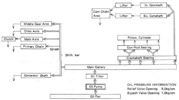
2. Carburetion
|
Manufacturer Model I.D.No. Main jet' Needle jet Pilot jet Starter jet Jet needle |
HITACHI 5N800 # 110 0 3.2 # 40 # 40(0 0.9) Y-10 |
Fuel level Pilot screw Air jet, Main Air jet, Pilot Throttle valve Float valve seat Engine idle speed |
3±1 mm (0.118+0.039 in) Preset # 50 # 205 32 mm (1.26 in) 0 2.0 1,050 r/min |
3. Chassis *Total weight of accessories, etc. excepting motorcycle.
|
Wheels and tires: |
2.0 mm (0.079 in) |
|
|
Tire pressure (cold): |
Front |
Rear |
|
Up to 90 kq (198 lb) load* 90 kg (198 lb) -160 kg (353 lb) load* 160 kg (353 lb)~230 kg (507 lb) load* High speed riding Minimum tire tread depth |
1.8 kg/cm2 (26 psi) 2.0kg/cm2(26psi) 2.0 kg/cm2 (28 psi) 2.3 kg/cm2 (36 psi) 0.8 mm (0.03 in) |
2.0 kg/cm2 (28 psi) 2.3 kg/cm2 (32 psi) 2.8 kg/cm2 (40 psi) 2.5 kg/cm2 (40 psi) 0.8 mm (0.03 in) |
|
Brakes: Recommended fluid Pad wear limit Rear brake lining wear limit Brake disc maximum deflection Brake disc minimum thickness Front brake free play (end of lever) Rear brake free play (end of pedal) |
DOT =3 6.5 mm (0.26 in) 2 mm (0.08 in) 0.15 mm (0.006 in) 6.5 mm (0.26 in) 5.0 ~ 8.0 mm (0.2-0.3 in) 20 ~ 30 mm (0.8 - 1.2 in) |
|
|
Front forks |
||
|
Travel Spring free length Spring preload length Spring rate: Fork oil capacity leach side) Oil type |
150 mm (5.91 in) 606 mm (23.86 in) 571 mm (22.48 in)
0.475 kg/mm (26.6 lb/in) 262 cc (9.24 oz) Yamaha Fork Oil 10Wt or equivalent |
|
|
Rear shock absorbers: |
||
|
Spring free length Spring preload length Spring rate: Travel |
232.5 mm (9.15 in) 216.5 mm (8.52 in)
1.6 kg/mm (89.6 lb/in) 80 mm (3.15 in) |
|
4. Electrical
Ignition timing retarded: 10°at 1,050 r/min
Ignition timing advance:
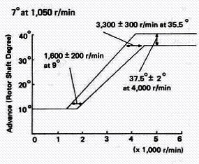
|
Spark plug: Electrode gap |
NGK BP7ES or ND W22EP 0.7 - 0.8 mm (0.023 - 0.032 in) |
|
Spark plug cap resistance: |
5.0kΩ (No. 1,No.4), 10kΩ (No. 2, No. 3) |
|
Pick up coil: Resistance |
700Ω ± 20% at 20°C(68°F) |
|
Ignition coil type: Spark gap Primary resistance Secondary resistance |
HITACHI CM12-09 2.5 Ω± 10%at20°C(68oFj 11kΩ± 20% at 20°C (68°F) |
|
Starter motor type: Armature coil resistance Brush length: Brush spring pressure Armature mica undercut |
Nippon Denso ADB4D2 0.014Ω ± 6% at 20°C (68°F)
12.0 mm (0.472 in) 800 ± 150g (28.24 ± 5.30 oz) 0.6 mm (0.024 in) |
|
Battery type: Charging rate |
G.S. 12N12A-4A 1.2 Amps for 10 Hours |
|
Generator type: Output Field (inner) coil resistance Stator (outer) coil resistance |
HITACHI LD119-08 14V-19A at 5,000 r/min 4.0Ω ±10%at20oC(68°F) 0.46 Ω ± 10% at 20°C (68°F) |
|
Regulator type: Regulated voltage Allowable amperage |
I.C. (S8534) 14.5 ± 0.3V 3A |
|
Starter relay switch: Cut-in voltage |
HONDA LOCK 8V |
|
Headlight: Tail/brake light: Flasher light: License light: Pilot lights: |
12V.50W/40W 12V, 8W (3CP)/27W (32CP) 12V, 27W(32CP) x4 12V, 8W (3CP) x2
12V,3.4Wx2 |
Torque Values
Torque ValuesTightening torque
(Unit: m-kg)
|
Part to be tightened |
Part name |
Thread size |
Q'ty |
Tightening torque |
Remarks |
||
|
m-kg |
ft-lb |
||||||
|
ENGINE: |
|||||||
|
Cylinder head |
Nut |
M10 P1.25 |
12 |
3.2 |
23.1 |
Apply oil. |
|
|
Cylinder head cover |
Bolt |
M6 P1.0 |
20 |
1.0 |
7.2 |
|
|
|
Spark plug |
— |
|
4 |
2.0 |
14.5 |
|
|
|
Cylinder |
Nut |
M8 P1.25 |
2 |
2.0 |
14.5 |
Cam chain case Front & Rear |
|
|
Cam shaft cap |
Bolt |
M6 P1.0 |
20 |
1.0 |
7.2 |
Tighten in 3-stages. |
|
|
Cam sprocket |
Bolt |
M7 P1.0 |
4 |
2.0 |
14.5 |
|
|
|
Cam chain tensioner adjustment lock nut |
Nut |
M8 P1.25 |
1 |
0.9 |
6.5 |
|
|
|
Cam chain tensioner adjustment lock bolt |
Bolt |
M6 P1.0 |
1 |
0.6 |
4.3 |
|
|
|
Connecting rod |
Nut |
M7 P0.75 |
8 |
2.5 |
18.1 |
|
|
|
Generator (rotor) |
Bolt |
M10 P1.25 |
1 |
5.5 |
39.8 |
|
|
|
Drain plug |
Bolt |
M14 P1.5 M8 P1.25 |
1 1 |
4.3 1.6 |
31.0 11.6 |
Crankcase drain Middle gear case drain |
|
|
Oil filter |
Bolt |
M20 P1.5 |
1 |
1.5 |
11.0 |
|
|
|
Pump cover |
Screw |
M6 P1.0 |
|
0.7 |
5.1 |
|
|
|
Strainer cover |
Bolt |
M6 P1.0 |
13 |
1.0 |
7.2 |
|
|
|
Crankcase |
Flange Bolt |
M8 P1.25 M6 P1.0 |
12 27 |
2.4 1.2 |
17.5 8.7 |
|
|
|
Clutch boss |
Nut |
M20 P1.0 |
1 |
7.2 |
52.0 |
|
|
|
Clutch spring screw |
Bolt |
M6 P1.0 |
5 |
1.0 |
7.2 |
|
|
|
Change pedal |
Bolt |
M6 P1.0 |
1 |
1.0 |
7.2 |
|
|
|
Neutral switch |
— |
M10 P1.25 |
1 |
2.0 |
14.5 |
|
|
|
Exhaust pipe |
Nut |
M6 P1.0 |
8 |
1.0 |
7.2 |
|
|
|
SHAFT DRIVE: |
|||||||
|
—Middle Gear — |
|
|
|
|
|
|
|
|
Drive Shaft |
Nut |
M34 P1.5 |
1 |
11 |
80.0 |
Stake. |
|
|
Mount cover |
Screw |
M8 P1.25 |
4 |
2.5 |
18.1 |
Stake. |
|
|
Driven shaft |
Nut |
M14 P1.5 |
1 |
12 |
87.0 |
Use LOCKTITE: Stake. |
|
|
Bearing cap |
Flange Bolt |
M8 PI.25 |
4 |
2.5 |
18.1 |
|
|
|
- Final Gear — |
|||||||
|
Drive shaft |
Nut |
M14 P1.5 |
1 |
11 |
80.0 |
|
|
|
Bearing housing |
Flange Bolt |
M10 P1.25 |
2 |
2.3 |
16.6 |
|
|
|
Bearing housing |
Nut |
M8 PI .25 |
6 |
2.3 |
16.6 |
|
|
|
Oil mount screw |
Plug |
M14 P1.5 |
1 |
2.3 |
16.6 |
|
|
|
Oil drain screw |
Plug |
M14 Pi .5 |
1 |
2.3 |
16.6 |
|
|
|
Bearing retainer |
— |
M65 P1.5 |
1 |
11 |
80.0 |
Left hand screw |
|
|
CHASSIS: |
|||||||
|
Engine Mounting Bolt |
Front, upper Rear |
Nut Bolt Nut |
M10 P1.25 M10 P1.25 M12 P1.25 |
1 2 1 |
4.2 4.2 7.0 |
30.4 30.4 50.6 |
|
|
Part to be tightened |
Part name |
Thread size |
Q'ty |
Tightening torque |
Remarks |
||
|
m-kg |
ft-lb |
||||||
|
Engine Mounting Stay |
Front |
Bolt |
M8 P1.25 |
4 |
2.0 |
14.5 |
|
|
Handle crown & Steering shaft |
Rolt Bolt |
M14 P1.25 M8 P1.25 |
1 1 |
5.4 2.0 |
39.1 14.5 |
|
|
|
Handle crown & Inner tube |
Nut cap |
M8 P1.25 |
1 |
2.0 |
14.5 |
|
|
|
Handle crown & Handle holder |
Bolt |
M8 P1.25 |
2 |
2.0 |
14.5 |
|
|
|
Front fork |
|||||||
|
Under bracket & Inner tube |
Bolt |
M8 P1.25 |
4 |
2.0 |
14.5 |
|
|
|
Front wheel shaft |
Nut Castle |
M14 P1.5 |
1 |
10.7 |
77.4 |
|
|
|
Front wheel Axle pinch bolt |
Nut self locking |
M8 P1.25 |
2 |
2.0 |
14.5 |
|
|
|
Pivot shaft |
Bolt |
M22 P1.5 |
1 |
0.55 |
4.0 |
Taper roller bearing |
|
|
Rear wheel shaft |
Nut castle |
M14 P1.5 |
1 |
10.7 |
77.4 |
|
|
|
Rear shock absorber (Upper) |
Nut cap |
M10 P1.25 |
2 |
3.0 |
21.7 |
|
|
|
Rear shock absorber (Lower) |
L Nut cap R Bolt |
M10 P1.25 |
2 |
3.0 |
21.7 |
|
|
|
Footrest |
Nut |
M10 P1.25 |
2 |
4.2 |
30.4 |
|
|
|
Tension bar & Brake plate |
Bolt |
M8 P1.25 |
1 |
2.0 |
14.5 |
|
|
|
Tension bar & Rear arm |
Bolt |
M8 P1.25 |
1 |
2.0 |
14.5 |
|
|
|
Camshaft lever & Camshaft |
Bolt |
M6 P1.0 |
1 |
0.9 |
6.5 |
|
|
|
Disc brake section |
|||||||
|
Brake disc & Hub (Front) |
Bolt |
M8 P1 .25 |
12 |
2.0 |
14.5 |
Lock washer |
|
|
Master cylinder & Brake hose (Front) |
Bolt union |
M10 P 1.25 |
1 |
2.6 |
18.8 |
|
|
|
Brake hose & Joint |
Bolt union |
M10 P1.25 |
1 |
2.6 |
18.8 |
|
|
|
Caliper & Brake hose |
Bolt union |
M10 P1.25 |
1 |
2.6 |
18.8 |
|
|
|
Caliper & Front fork (Front) |
|
M8 PI.25 |
1 |
2.6 |
18.8 |
|
|
|
Caliper bleed screw (Front) |
|
M8 P1.25 |
1 |
0.6 |
4.3 |
• |
|
|
Front fender |
Bolt |
M8 P1.25 |
4 |
1.0 |
7.2 |
|
|
|
Master cylinder cap |
Screw |
M5 P0.8 |
2 |
0.18 |
1.3 |
|
|
|
Pivot shaft |
Bolt |
M22 P1.5 |
1 |
10.0 |
72.3 |
Lock washer |
|
|
Final gear & Rear arm |
Nut |
M10 P1.25 |
4 |
4.2 |
30.4 |
|
|
|
Cross Joint |
Hexagon bolt with washer |
M8 P1.25 |
4 |
4.4 |
31.8 |
|
|
|
Muffler bracket & Frame |
Bolt |
M10 P1.25 |
3 |
4.3 |
31.1 |
|
|
|
Rear fender |
Bolt |
M10 P1.25 |
2 |
3.2 |
23.1 |
|
|
|
Muffler bracket & Muffler |
Bolt |
M10 P1.25 |
2 |
2.5 |
18.1 |
|
|
|
Master cylinder & Master cylinder bracket |
Bolt |
M6 P1.0 |
2 |
0.9 |
6.5 |
|
|
General Torque Specifications This chart specifies torque for standard fasteners with standard I.S.O. pitch threads. Torque specifications for special components or assemblies are included in the applicable sections of this book. To avoid warpage, tighten multi-fastener assemblies in a criss-cross fashion, in progressive stages, until full torque is reached. Unless otherwise specified, torque specifications call for clean, dry threads. Components should be at room temperature.
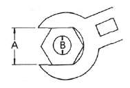
|
A (Nut) |
B (Bolt) |
General torque specifications |
|
|
m-kg |
ft-lb |
||
|
10 mm |
6 mm |
0.6 |
4.5 |
|
12 mm |
8 mm |
1.5 |
11 |
|
14 mm |
10 mm |
3.0 |
22 |
|
17 mm |
12 mm |
5.5 |
40 |
|
19 mm |
14 mm |
8.5 |
51 |
|
22 mm |
16 mm |
13.0 |
94 |
CONVERSION TABLES
|
METRIC TO INCH SYSTEM |
|||
|
|
KNOWN |
MULTIPLIER |
RESULT |
|
TORQUE |
m-kg |
7.233 |
ft-lb |
|
m-kg |
86.80 |
in-lb |
|
|
cm-kg |
0.0723 |
ft-lb |
|
|
cm-kg |
0.8680 |
in-lb |
|
|
WT. |
kg |
2.205 |
lb |
|
9 |
0.03527 |
oz |
|
|
FLOW / DISTAMCE |
km/lit |
2.352 |
mpg |
|
km/hr |
0.6214 |
mph |
|
|
km |
0.6214 |
mi |
|
|
m |
3.281 |
ft |
|
|
m |
1.094 |
yd |
|
|
cm |
0.3937 |
in |
|
|
mm |
0.03937 |
in |
|
| VOLUME/
CAPACITY |
cc (cm3) |
0.03382 |
oz (US liq) |
|
cc (cm ) |
0.06102 |
cu. m |
|
|
lit (liter) |
2.1134 |
pt (US liq) |
|
|
lit (liter) |
1.057 |
qt (US liq) |
|
|
lit (liter) |
0.2642 |
gal (US liq) |
|
| MISC. |
kg/mm |
56.0C7 |
lb/in |
|
kg/cm |
14.2234 |
psi (lb/in2) |
|
| Centigrade (°C) | 9/5(°C) + 32 | Fahrenheit (° F) | |
|
INCH TO METRIC SYSTEM |
|||
|
|
KNOWN |
MULTIPLIER |
RESULT |
| TORQUE |
ft-lb |
0.13826 |
m-kg |
|
in-lb |
0.01152 |
m-kg |
|
|
ft-lb |
13.831 |
cm-kg |
|
|
in-lb |
1.1521 |
cm-kg |
|
|
WT. |
lb |
0.4535 |
kg |
|
oz |
28.352 |
g |
|
| FLOW /
DISTANCE |
mpg |
0.4252 |
km/lit |
|
mph |
1.609 |
km/hr |
|
|
mi |
1.609 |
km |
|
|
ft |
0.3048 |
m |
|
|
yd |
0.9141 |
m |
|
|
in |
2.54 |
cm |
|
|
in |
25.4 |
mm |
|
|
VOLUME / CAPACITY |
oz (US liq) |
29.57 |
cc (cm ) |
|
cu.in |
16.387 |
cc "cm ) |
|
|
pt (US liq) |
0.4732 |
lit (liter) |
|
|
qt (US liq) |
0.9461 |
lit (liter) |
|
|
gal (US liq) |
3.785 |
lit (liter) |
|
|
MISC. |
lb/in |
0.017855 |
kg/mm |
|
psi (lb/in ) |
0.07031 |
kg/cm2 |
|
|
Fahrenheit (°C) |
5/9(°F-32) |
Centigrade (°F) |
|
|
DEFINITION OF TERMS: |
||
|
m-kg |
= |
Meter-kilogram(s) (usually torque) |
|
9 |
= |
Gram(s) |
|
kg |
= |
Kilogram(s) (1,000 grams) |
|
lit |
= |
Liter(s) |
|
km/lit |
= |
Kilometer(s) per liter (fuel consumption) |
|
cc |
= |
Cubic centimeter(s) (cm3) (volume or capacity) |
|
kg/mm |
= |
Kilogram(s) per millimeter (usually spring compression rate) |
|
kg/cm2 |
= |
Kilogram(s) per square centimeter (pressure) |
Consumer Information
Consumer InformationCONSUMER INFORMATION
Notice
The information presented represents results obtainable by skilled drivers under controlled road and vehicle conditions, and the information may not be correct under other conditions.
STOPPING DISTANCE
This figure indicates braking performance that can be met or exceeded by the vehicles to which it applies, without locking the wheels, under different conditions of loading and with partial failures of the braking system.
FULL OPERATIONAL SERVICE BRAKE
("Partial failure" information is not applicable and is not included)
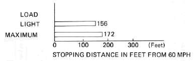
ACCELERATION AND PASSING ABILITY
This figure indicates passing times and distances that can be met or exceeded by the vehicles to which it applies, in the situations diagrammed below. The low-speed pass assumes an initial speed of 20 mph. and a limiting speed of 35 mph. This high-speed pass assumes an initial speed of 50 mph. and a limiting speed of 80 mph.
LOW-SPEED PASS
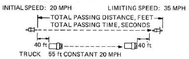
HIGH-SPEED PASS
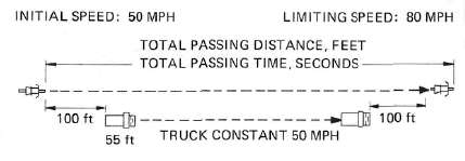
SUMMARY
Low-speed pass ........................................ 353.0 feet: 7.15 seconds
High-speed pass ........................................ 883.4 feet: 8.4 seconds
Lubrication Diagrams
Lubrication DiagramsLUBRICATION DIAGRAMS
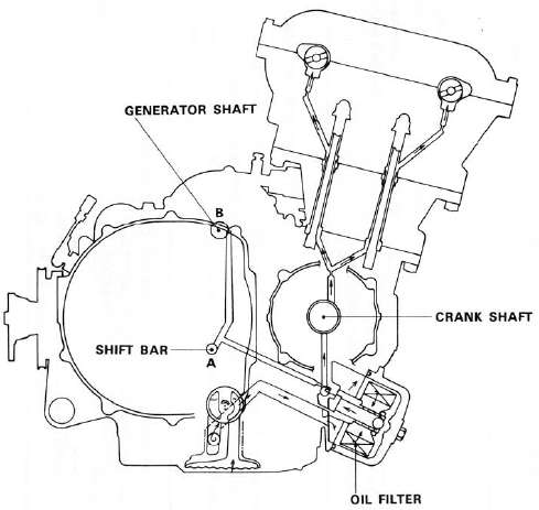
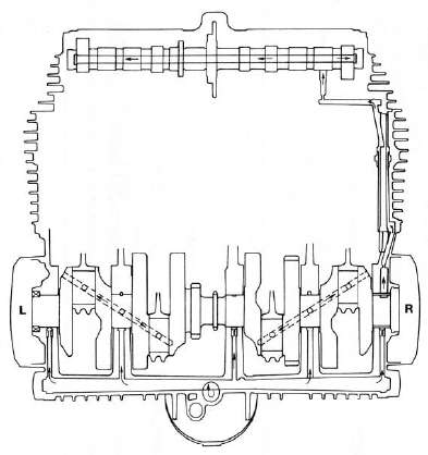
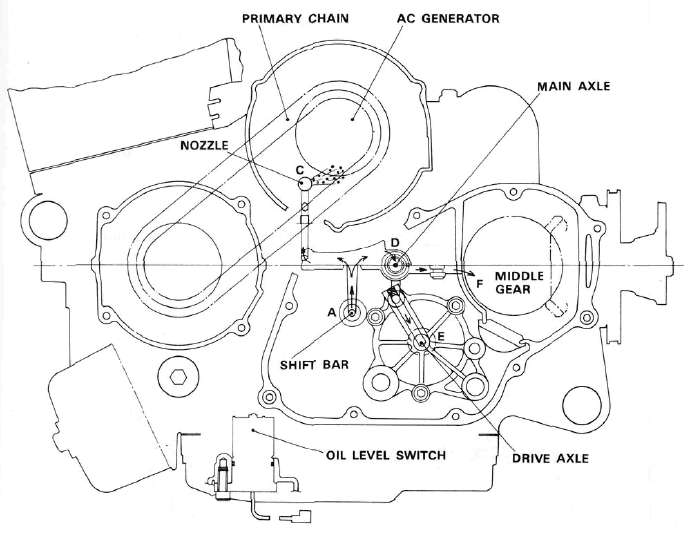
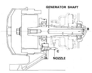
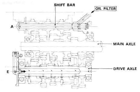

Cable Routing
Cable RoutingCABLE ROUTING
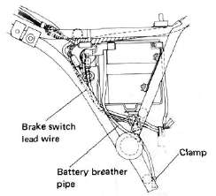
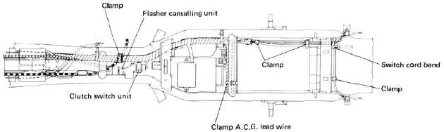
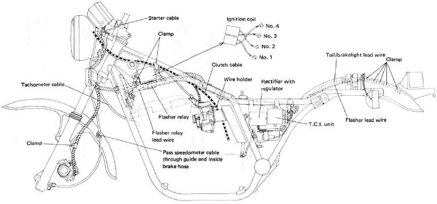
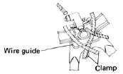
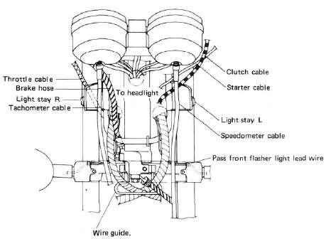
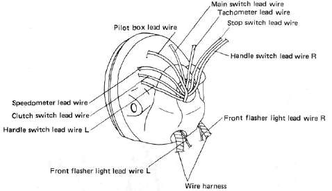
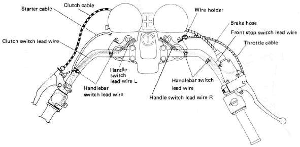
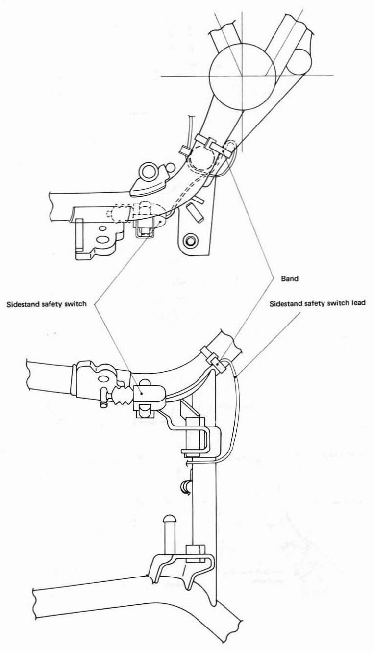
Parts Illustrations
Parts IllustrationsPARTS ILLUSTRATIONS
Clutch
ClutchCLUTCH
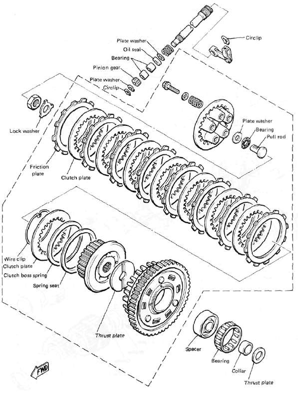
Transmission
Transmission
TRANSMISSION
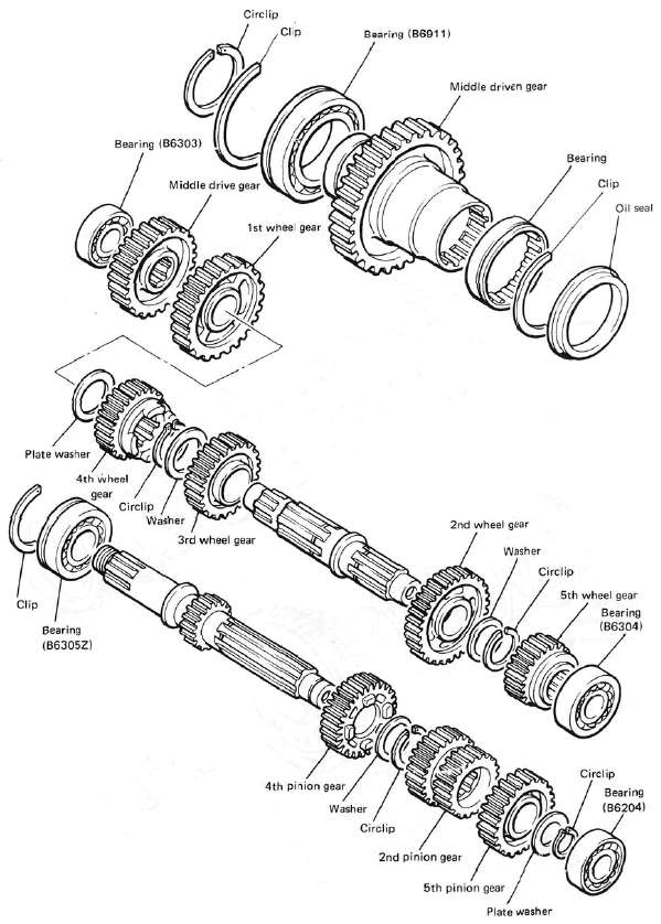
Middle Gear Damper
Middle Gear DamperMIDDLE GEAR/DAMPER
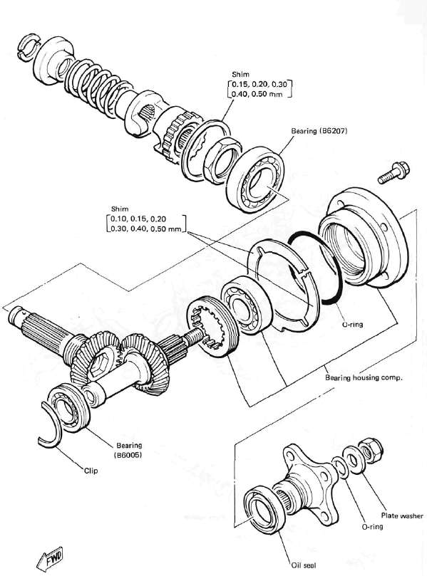
Final Gear / Driveshaft
Final Gear / DriveshaftFINAL GEAR / DRIVE SHAFT
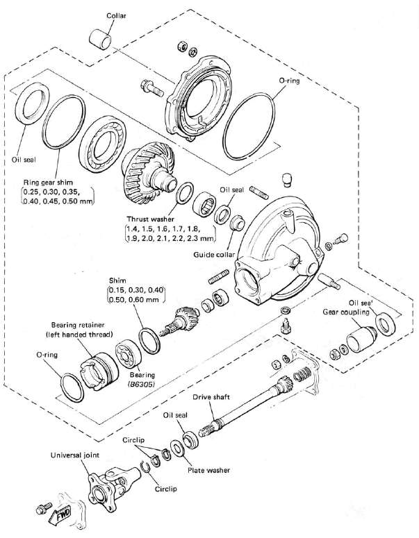
Front Wheel
Front WheelFRONT WHEEL
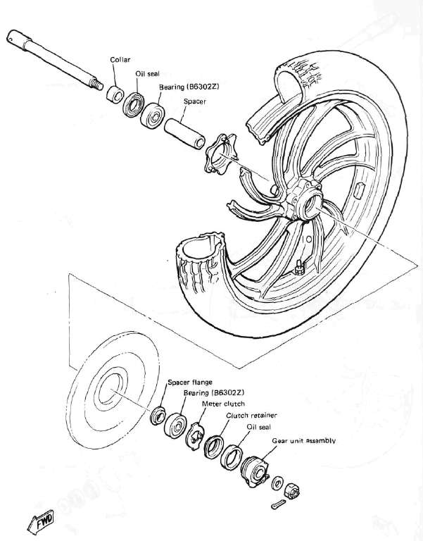
Rear Wheel
Rear WheelREAR WHEEL
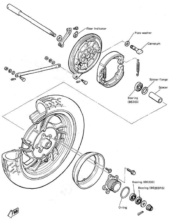
Front Brake
Front BrakeFRONT BRAKE (MASTER CYLINDER)
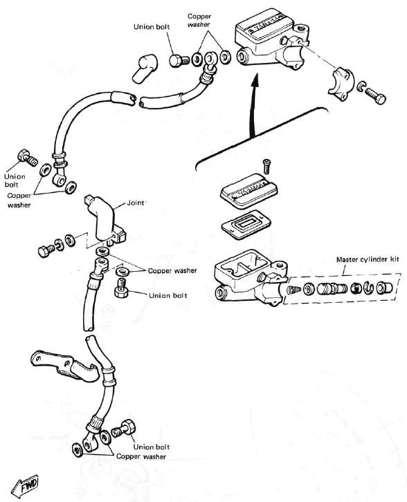
FRONT BRAKE (CALIPER)

Middle Gear Damper
Middle Gear DamperMIDDLE GEAR/DAMPER
Electrical Component Locations
Electrical Component LocationsELECTRICAL COMPONENTS
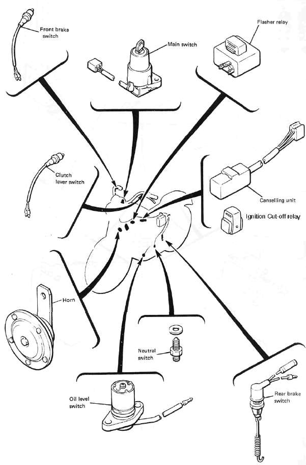
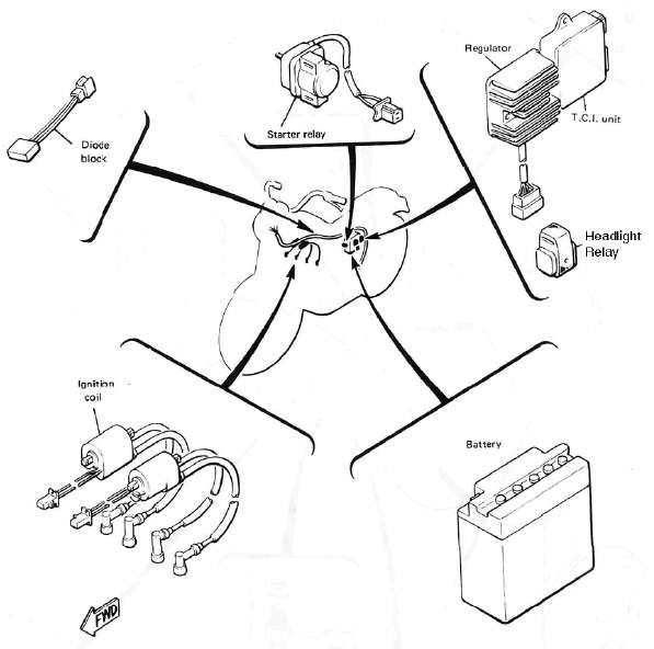
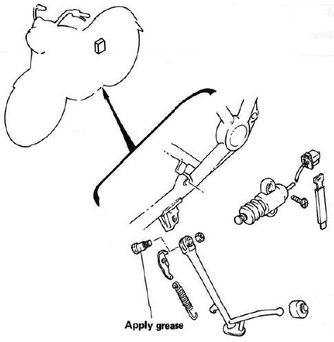
Sidestand switch
Wiring Diagram
Wiring DiagramWIRING DIAGRAM