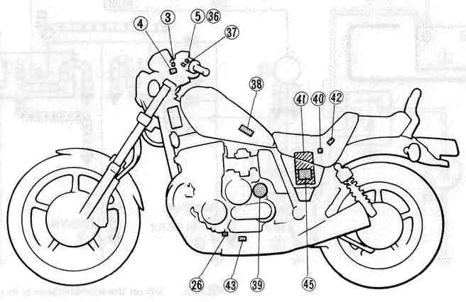
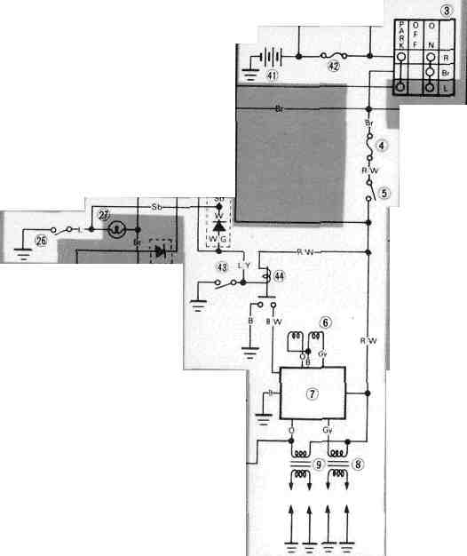
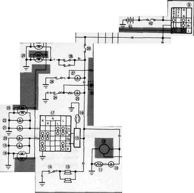
Chapter 6, ELECTRICAL
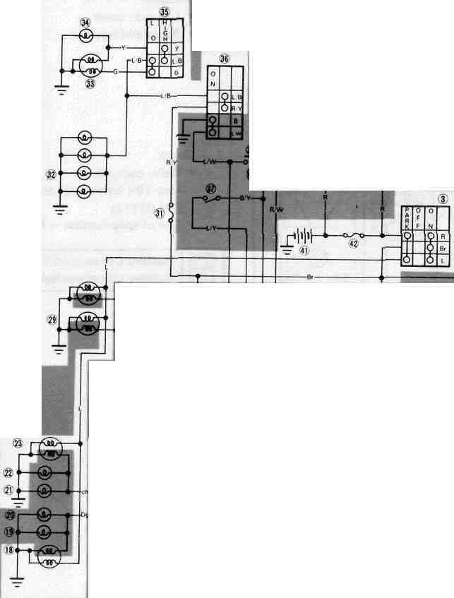
Chapter 6, ELECTRICALWiring Diagram
Wiring Diagram
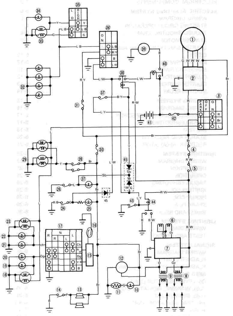
1 A.C. Generator 2 Rectifier/Regulator 3 Main switch 4 Fuse "IGNITION" (10A)
5 Engine stop switch 6 Pickup coil 7 T.C.I. Unit 8 Ignition coil {No. 1, 4) 9 Ignition coil (No. 2, 3)
10 "FUEL" indicator light 11 Fuel sender 12 Tacho meter 13 Horn 14 Horn switch
15 Flasher relay (Relay assembly) 16 Reed switch 17 Flasher switch 18 Flasher light (Front, Right)
19 Flasher light (Rear, Right) 20 "TURN" indicator light (Right) 21 "TURN" indicator light (Left)
22 Flasher light (Rear, Left) 23 Flasher light (Front, Left) 24 Oil level switch 25 "OIL" indicator light
26 Neutral switch 27 "NEUTRAL" indicator light 28 Brake switch 29 Tail/Brake light
30 Fuse "SIGNAL" (15A) 31 Fuse "HEAD" (15A) 32 Meter light 33 Head light
34 "HIGH BEAM" indicator light 35 Dimmer switch 36 Starter switch 37 Clutcn switch
38 Starting circuit cut-off relay (Relay assembly) 39 Starter motor 40 Starter relay 41 Battery
42 Fuse "MAIN" (30A) 43 Sidestand switch 44 Sidestand relay 45 Diode assembly
COLOR CODE
|
0 |
Orange |
Lg |
Light green |
B/Y |
Black/Yellow |
|
R |
Red |
Y/G |
Yellow/Green |
L/W |
Blue/White |
|
L |
Blue |
Y/R |
Yellow/Red |
L/G |
Blue/Green |
|
Br |
Brown |
Y/B |
Yellow/Black |
L/R |
Blue/Red |
|
B |
Black |
Y/L |
Yellow/Blue |
L/B |
Blue/Black |
|
Y |
Yellow |
Br/W |
Brown/White |
G/L |
Green/Blue |
|
W |
White |
R/B |
Red/Black |
G/R |
Green/Red |
|
G |
Green |
R/L |
Red/Blue |
G/Y |
Green/Yellow |
|
P |
Pink |
R/W |
Red/White |
G/W |
Green/White |
|
Dg |
Dark green |
R/Y |
Red/Yellow |
W/R |
White/Red |
|
Ch |
Chocolate |
B/R |
Black/Red |
W/B |
White/Black |
|
Gy |
Gray |
B/W |
Black/White |
W/G |
White/Green |
|
Sb |
Sky blue |
|
|
|
|
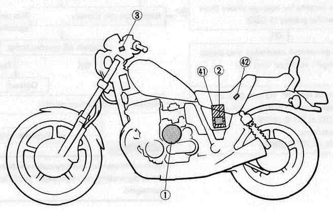
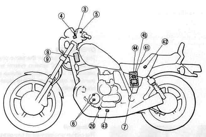
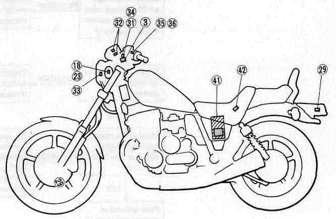
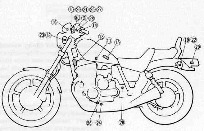
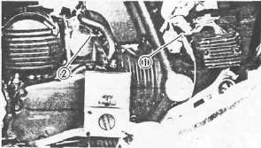
Electrical Components
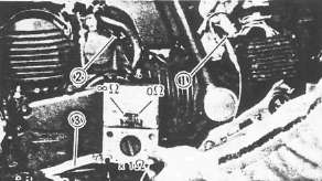
Electrical ComponentsELECTRICAL COMPONENTS 1

1 Fuse 2 Main switch 3 Front brake switch 4 TCI unit Main fuse Battery
5 Neutral switch 6 Rear brake switch 7 Sidestand switch 8 Oil level switch
9 Ignition coil
ELECTRICAL COMPONENTS 2
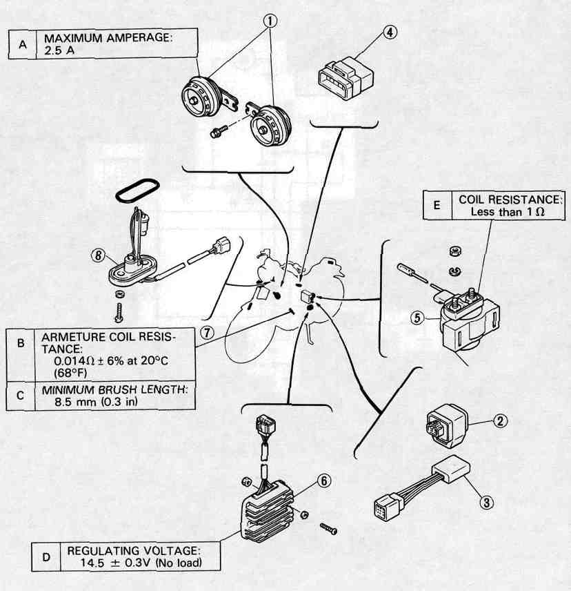
1 Horn 2 Sidestand relay 3 Diode assembly
4 Relay assembly (Starting circuit cut-off relay, flasher relay)
5 Starter relay 6 Rectifier/Regulator 7 Starter motor
8 Fuel sender
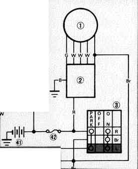
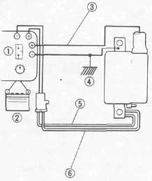
Electric Starting System
Electric Starting SystemELECTRIC STARTING SYSTEM
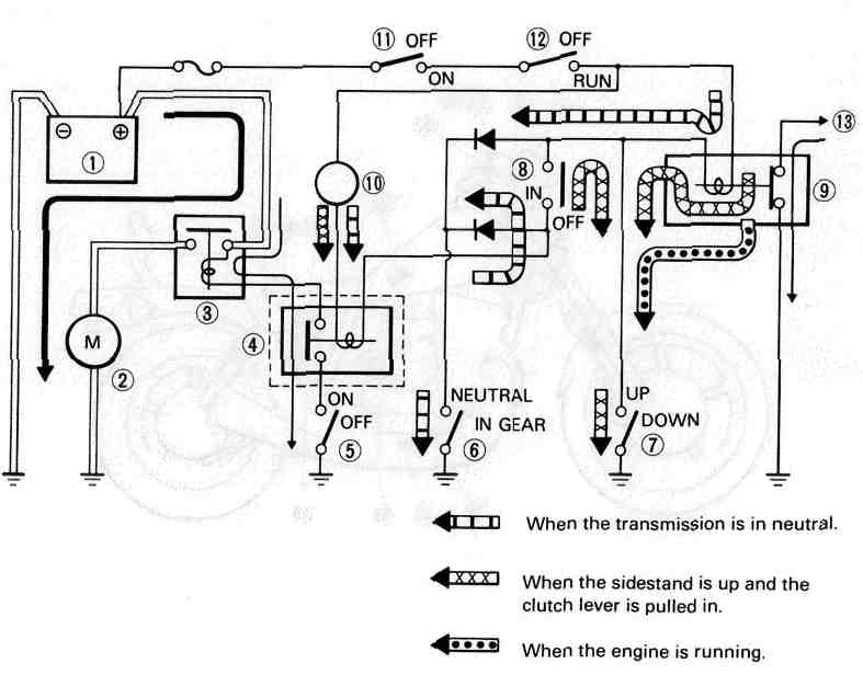
CIRCUIT DIAGRAM
Below circuit diagram shows starter circuit in wiring diagram.
.
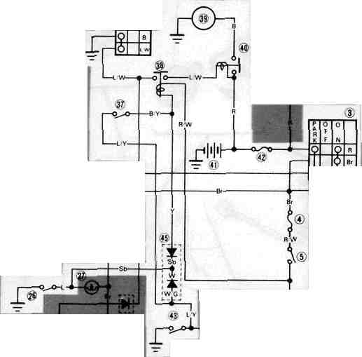
3 Main switch
4 Fuse "IGNITION" (10A)
5 Engine stop switch
26 Neutral switch
36 Starter switch
37 Clutch switch
38 Starting circuit cut-off relay (Relay assembly)
39 Starter motor
40 Starter relay
41 Battery
42 Fuse "MAIN" (30A)
43 Sidestand switch 45 Diode
COLOR CODE
|
0 |
Orange |
Lg |
Light green |
B/Y |
Black/Yellow |
|
R |
Red |
Y/G |
Yellow/Green |
L/W |
Blue/White |
|
L |
Blue |
Y/R |
Yellow/Red |
L/G |
Blue/Green |
|
Br |
Brown |
Y/B |
Yellow/Black |
L/R |
Blue/Red |
|
B |
Black |
Y/L |
Yellow/Blue |
L/B |
Blue/Black |
|
Y |
Yellow |
Br/W |
Brown/White |
G/L |
Green/Blue |
|
W |
White |
R/B |
Red/Black |
G/R |
Green/Red |
|
G |
Green |
R/L |
Red/Blue |
G/Y |
Green/Yellow |
|
P |
Pink |
R/W |
Red/White |
G/W |
Green/White |
|
Dg |
Dark green |
R/Y |
Red/Yellow |
W/R |
White/Red |
|
Ch |
Chocolate |
B/R |
Black/Red |
W/B |
White/Black |
|
Gy |
Gray |
B/W |
Black/White |
W/G |
White/Green |
|
Sb |
Sky blue |
|
|
|
|
ELECTRIC STARTING SYSTEM
STARTING CIRCUIT OPERATION
The starting circuit on this model consists of the starter motor, starter relay, starter safety unit, and sidestand relay. If the engine stop switch and the main switch are both on, the starter motor can operate only if:
• The transmission is in neutral (the neutral switch is on.)
• The sidestand is up (the sidestand switch is on) and the clutch lever is pulled in (clutch switch is on).
Battery Starter motor Starter relay Starter safety unit (Relay assembly) Starter switch Neutral switch
Sidestand switch Clutch switch Sidestand relay Tachometer Main switch Engine stop switch To ignitor switch
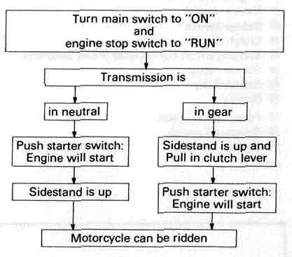
1 Battery 2 Starter motor 3 Starter relay 4 Starting circuit cut-off relay
5 Starter switch 6 Neutral switch 7 Sidestand switch 8 Clutch switch
9 Sidestand relay 10 Tachometer 11 Main switch 12 Engine stop switch
13 To ignitor unit
|
Turn main switch to "ON" and engine stop switch to "RUN" |
|
|
Transmission is |
|
|
▼ |
▼ |
|
In neutral |
In gear |
|
▼ |
▼ |
|
Push starter switch Engine will start |
Raise Sidestand and Pull in clutch lever |
|
▼ |
▼ |
|
Ensure Sidestand is up |
Push starter switch: Engine will start |
|
▼ |
▼ |
|
Motorcycle can be ridden |
|
TROUBLESHOOTING CHART
|
THE STARTER MOTOR DOES NOT OPERATE. |
|
|
|
▼ |
|
|
|
|
||
|
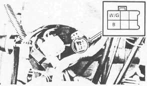
Connect "L/W" lead from the starter relay 1 to the battery negative (-) terminal 2 ; use a jumper lead. |
► |
The engine does not rev smoothly. |
|
▼ |
||
|
Recharge or replace the battery. |
||
|
|
||
|
► |
The engine does not operate. | |
|
▼ |
||
|
▼ |
|
|
|
Check the battery voltage (12V) on the "L/W" lead from the starter relay. |
||
|
The engine operates. |
||
|
▼ |
||
|
▼ |
||
|
Main and engine stop switches are turned to "ON". |
||
|
If the starter relay does not click, check the starter relay and starter motor. |
||
| ▼ | ||
|
|
||
|
|
||
|
Connect "B/Y" lead to "ground" on the frame; use a jumper lead 1. |
||
|
► |
|
|
|
If the relay unit does not click, check the battery voltage (12V) on the "R/W" lead. |
||
|
|
▼ |
|
|
Check for an open or poor connection between the main switch and relay unit. |
||
|
▼ |
||
|
If the relay unit clicks, check the starter, sidestand, clutch and neutral switches. Replace switch(es) if necessary. |
|
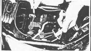

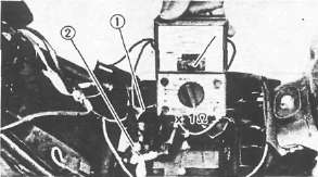
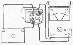
STARTER SAFETY UNIT (Relay Assembly)
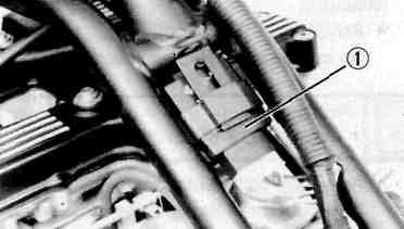
1. Remove:
• Seat
• Fuel tank
• Relay assembly ®
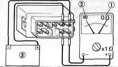
2. Check:
• Relay contacts Use 12V battery (§) and Pocket Tester (YU-03112). Out of specification — Replace relay.
Battery Connected: OH ® Battery disconnected: °° ©
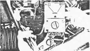
DIODE
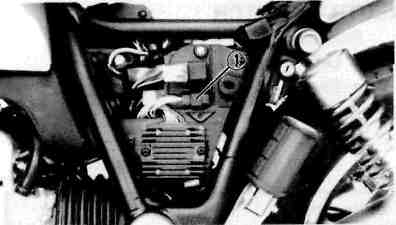
1. Remove:
• Left side cover
• Diode ®
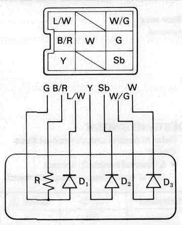
2. Check:
• Diode continuity/discontinuity
Defective element(s) — Replace the unit.
|
Checking element |
Pocket tester connecting point |
Good |
|
|
(+) (red) |
(-) (black) |
||
|
D, |
G |
L/W |
O |
|
L/W |
G |
X |
|
|
D2 |
Y |
Sb |
o |
|
Sb |
Y |
X |
|
|
D3 |
W/G |
W |
o |
|
W |
W/G |
X |
|
|
R |
G |
B/R |
8.20 |
O: Continuity (OH) (Scale H x 1000) X : Discontinuity («>) (Scale ohm x 1)
NOTE:
The results "O" or "X" should be reversed according to the pocket tester polarity.
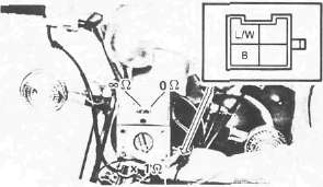
NEUTRAL SWITCH
1. Remove:
• Left side cover
• Panel
2. Check the neutral switch contact. Replace if out of specification.
|
Shift pedal 3 |
In neutral |
In gear |
|
Tester |
0Ω |
∞Ω |
1 Blue lead
2 Ground
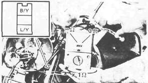
SIDESTAND SWITCH
1. Refer to neutral switch removal steps.
2. Check the sidestand switch 1 contact. Replace switch if out of specification.
|
Sidestand |
Up 2 |
Down 3 |
|
Tester |
0Ω |
∞Ω |
CLUTCH SWITCH
1. Remove headlight unit
2. Check clutch switch contact. replace if out of specification.
|
Clutch lever |
Pull in |
Not pull in |
|
Tester |
0Ω |
∞Ω |
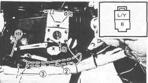
STARTER SWITCH
1. Remove the headlight unit.
2. Check starter switch contact. Replace if out of specification.
|
Starter switch |
ON |
OFF |
|
Tester |
0Ω |
∞Ω |
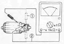
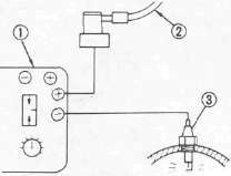
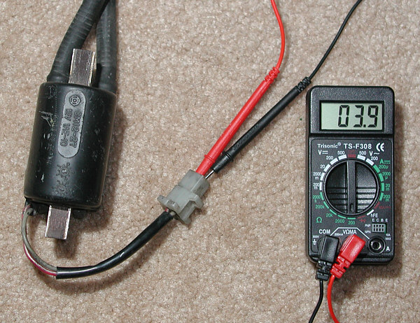
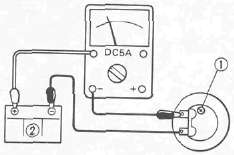
STARTER RELAY Inspection
Preparation steps:
• Disconnect starter motor red lead.
• Connect Pocket Tester leads to relay terminals.
•Turn main switch to "ON".
• Turn engine stop switch to "RUN".
• Move shift pedal to "NEUTRAL"
|
Push starter switch to "ON" |
||
|
▼ |
▼ |
|
|
Relay clicks and tester reads 0Ω |
Relay does not click and tester does not read 0 Ω |
|
|
▼ |
▼ |
|
|
OK |
Measure resistance: |
|
|
|
||
|
▼ |
▼ | |
|
Resistance less than 1 Ω |
Resistance more than 1 Ω | |
|
▼ |
▼ | |
|
Check connections |
Replace relay | |
Starter Motor
Starter MotorSTARTER MOTOR
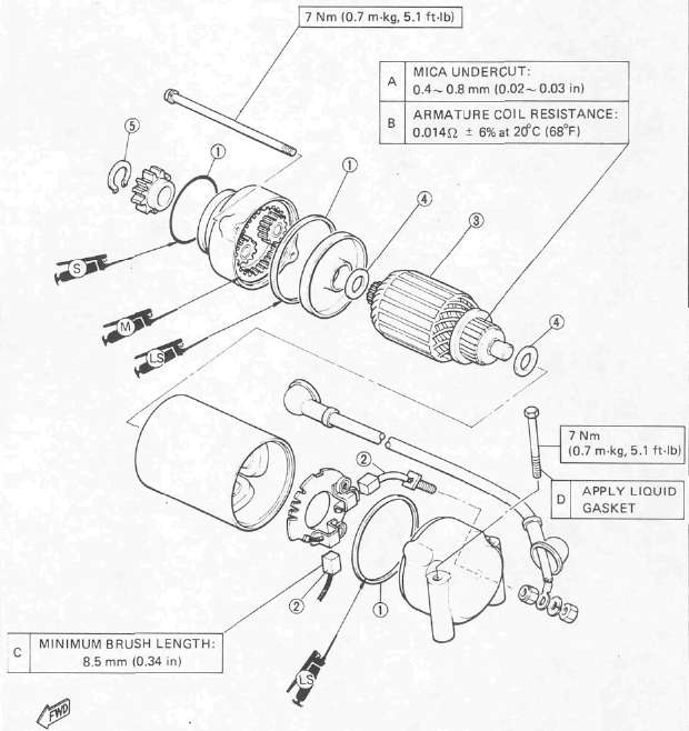
1 O-ring
2 Brush
3 Armature
4 Washer
5 Circlip
Removal
Refer Chapter 3. "ENGINE DISASSEMBLY".
Inspection
1. Inspect commutator outer surface. Clean with 600 grit sandpaper if dirty. Check mica insulation between commutator segments and scrape mica to proper limits. Use a hacksaw blade that is ground to fit.
Mica Undercut 1 : 0.4 - 0.8 mm (0.02 - 0.03 in)
NOTE:
The mica insulation of commutator must be under-cut to ensure proper operation of commutator.
2. Measure the armature coil continuity 1. Replace or rewind starter motorif necessary.
Armature Coil: 0.014Ω ± 6% at 20°C (68° F)
Measure the armature coil insulation 2. Replace the starter motor if shorted.
3. Inspect:
• Front cover bearing 1
• Center and rear covers bushings 2
Replace if damaged.
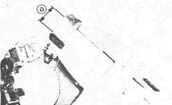
4. Measure the length of each brush length a and replace if less than minimum length.
Minimum Brush Length: 8.5 mm (0.34 in)
5. Check the brush spring pressure and compare with new spring. Replace spring if weak.
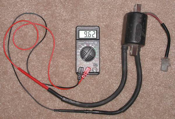
Charging System
Charging SystemCHARGING SYSTEM
1 A.C. Generator 2 Rectifier/Regulation 3 Main switch
41 Battery 42 Fuse "MAIN" (30A)
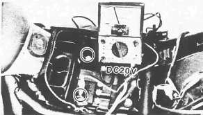
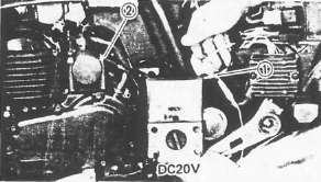
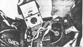
CHARGING VOLTAGE INSPECTION
1. Remove seat
2. Connect Pocket Tester leads (to each battery terminal)
3. Start the engine.
4. Measure the charging voltage. Rev engine to approximately 3,000 r/min or more.
Charging Voltage: 14.2 ~ 14.8 V
TROUBLESHOOTING
| Check voltage. | ◄ ◄ ◄ ◄ | ◄ | |
| Not within specification ▼ | ▲ | ||
|
Inspect all connections |
Defective ► | Correct.► | ▲ |
| OK ▼ | |||
| Measure the battery for voltage and specific gravity. Battery voltage: More than 12V Specific gravity: 1.280 |
Less than specification: ► | Recharge the battery. | |
|
OK ▼ |
|||
|
Remove the generator assembly and check the brush length, rectifier, and coil resistance. Minimum brush length: 10 mm (0.39 in) |
Less than specification: ► | Replace the defective part(s). | |
|
OK ▼ |
|||
| Replace rectifier/regulator. | |||
BATTERY
NOTE:
Replace the battery if:
•Battery voltage will not rise to a specific value or bubbles fail to rise even after many hours of charging.
•Sulfation of one or more cells occurs, as indicated by the plates turning white, or an accumulation of material exists in the bottom of the cell.
•Specific gravity readings after a long, slow charge indicate one cell to be lower than the rest.
•Warpage or buckling of plates or insulators is evident.
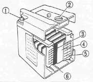
1 Terminal
2 Cap
3 Insulator
4 Separation plate
5 Negative electrode
6 Positive electrode
1. Inspect the battery terminals and battery couplers. Clean off any corrosion. Tighten as required.
2. Measure the specific gravity of battery fluid. Remove and recharge battery if less than 1.280
CAUTION:
To insure maximum battery performance be sure to:
• Charge a new battery before use.
• Maintain proper electrolyte level.
• Charge at proper current; 1.4 amps/10 hrs. or until the specific gravity reaches 1.280 at 20°C(68°F).
Failure to observe these points will result in a shortened battery life.

WARNING:
Battery electrolyte is dangerous; it contains sulfuric acid and therefore is poisonous and highly caustic.
Always follow these preventive measures:
•Avoid bodily contact with electrolyte as it can cause severe burns or permanent eye injury.
•Wear protective eye gear when handling or working near batteries. Antidote (EXTERNAL):
•SKIN - Flush with water.
•EYES — Flush with water for 15 minutes and get immediate medical attention. • Drink large quantities of water or milk and follow with milk of magnesia, beaten egg, or vegetable oil. Get immediate medical attention.
Batteries also generate explosive hydrogen gas, therefore you should always follow these preventive measures:
• Charge batteries in a well-ventilated area.
• Keep batteries away from fire, sparks, or open flames (e.g., welding equipment, lighted cigarettes, etc.)
• DO NOT SMOKE when charging or handling batteries. KEEP BATTERIES AND ELECTROLYTE OUT OF REACH OF CHILDREN.
Battery Service Life
The service life of a battery is usually two to three years. Battery life may be shortened by poor maintenance.
Preparation steps:
• Keep battery topped off with distilled water.
• Keep battery charged.
• Do not overcharge battery.
• Do not allow battery to freeze.
• Do not fill with tap water or sulfuric acid containing impurities.
• Do not charge new battery using improper voltage or current.
Battery Storage
The battery should be stored if the motorcycles is not to be used for a long period.
1. Remove the battery.
Battery storage and maintenance tips:
• Recharge the battery periodically.
• Store the battery in a cool, dry place.
• Recharge the battery before reinstalling.
|
Battery |
YB14L |
|
Electrolyte |
Specific gravity: 1.280 |
|
Initial charging rate |
1.4 amp for 10 hours (new battery) |
|
Recharging rate |
10 hours (or until specific gravity reaches 1.280) |
|
Refill fluid |
Distilled water (to maximum level line) |
|
Refill period |
Check once per month (or more often as required) |
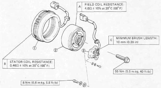
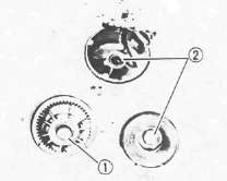
1 Field coil
2 Stator
3 Brush
GENERATOR ASSEMBLY
1. Remove:
• Left side cover
• Panel
2. Measure the stator coil resistance
Stator Coil Resistance: 0.46Ω ± 10% at 20°C (68°F) (W-W)

3. Remove the A.C.G. cover
4. Measure the field coil resistance
Field Coil Resistance: 4.0Ω ±10% at 20°C (68°F)
5. Inspect the brush contact areas. Clean with 600 grit sandpaper if dirty.
6. Measure each brush length 1. Replace if shorter than minimum.
Minimum Brush Length: 10 mm (0.39 in)
2 Wear indicator
7. Inspect the brush springs Compare with new spring.
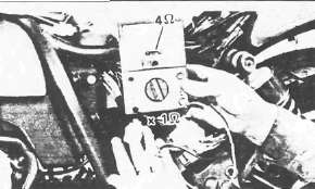
RECTIFIER/REGULATOR
1. Remove:
• Left side cover
• Panel
2. Check Rectifier/Regulator 1 diodes (Refer to the following table.)
Defective element — Replace rectifier.
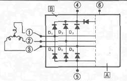
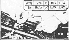
1 White
2 White
3 White
4 Red
5 Ground
6 Brown
A Regulator
B Rectifier
|
Checking |
Pocket tester |
Good |
|
|
(+) |
(-) |
||
|
D1 |
4 |
1 |
O |
|
1 |
4 |
X |
|
|
D2 |
4 |
2 |
O |
|
2 |
4 |
X |
|
|
D3 |
4 |
3 |
O |
|
3 |
4 |
X |
|
|
D4 |
1 |
5 |
O |
|
5 |
1 |
X |
|
|
D5 |
2 |
5 |
O |
|
5 |
2 |
x |
|
|
D6 |
3 |
5 |
O |
|
5 |
3 |
x |
|
O: Continuity X: Discontinuity (∞ )
CAUTION:
Do not overcharge rectifier or damage may result.
Avoid:
• A short circuit
• Inverting + and - battery leads
• Direct connection of rectifier to battery
NOTE:
The results "O" or "x" should be reversed according to the pocket tester polarity.
Ignition System
Ignition SystemIGNITION SYSTEM
3 Main switch
4 Fuse "IGNITION" (10A)
5 Engine stop switch
6 Pickup coil
7 T.C.I. Unit
8 Ignition coil (No. 1, 4)
9 Ignition coil (No. 2, 3)
26 Neutral switch
41 Battery
42 Fuse "MAIN" (30A)
43 Sidestand switch
44 Sidestand relay
45 Diode
DESCRIPTION
This model is equipped with a battery operated, fully transistorized, breakerless ignition system. By using magnetic pickup coils, the need for contact breaker points is eliminated. This adds to the dependability of the system by eliminating frequent cleaning and adjustment of points and ignition timing. The TCI (Transistor Control Ignition) unit incorporates an automatic advance circuit controlled by signals generated by the pickup coil. This adds to the dependability of the system by eliminating the mechanical advancer. This TCI system consists of two units; a pickup unit and an ignitor unit.
OPERATION
The TCI functions on the same principle as a conventional DC ignition system with the exception of using magnetic pickup coils and a transistor control box (TCI) in place of contact breaker points.
Pickup Unit
The pickup unit consists of two pickup coils and a flywheel mounted onto the crankshaft. When the projection on the flywheel passes a pickup coil, a signal is generated and transmitted to the ignitor unit. The width of the projection on the flywheel determines the ignition advance.
1 Pickup coils
Ignitor Unit
This unit controls wave form, duty control, switching, electronic ignition advance, etc. The duty control circuit reduces electrical consumption by controlling the duration of the primary ignition current.
The ignitor unit 1 also has a protective circuit for the ignition coil. If the ignition switch is on and the crankshaft is not turning, the protective circuit interrupts the current flow to the primary coil after a few seconds. When the crankshaft is turning, however, the ignitor unit sends current to the primary coil.
1. Remove:
• Seat
• Left side cover
• Panel
• Ignitor unit 1
TROUBLESHOOTING
1. Start engine and warm-up a while, then turn it off.
2. Connect Electro Tester (90890-03021) 1
2 Spark plug wire
3 Spark plug
3. Start engine and increase spark gap until misfire occurs (Test at various rpm between idle and red line.)
CAUTION:
Do not run the engine in neutral above 6,000 rpm for more than 1 or 2 seconds.
Minimum Spark Gap: 6 mm (0.24 in)
4. If ignition system becomes inoperative or engine misfires see the troubleshooting chart below:
Troubleshooting Chart
|
Check entire ignition connections. |
Poor connection ► |
Correct.
|
|
▼ OK |
||
|
Check battery voltage and specific gravity. |
Low voltage/specific gravity ► |
Recharge battery.
|
|
▼ OK |
||
|
Check fuse and fuse connections. |
Weak connection or open circuit ► |
Correct connection or replace fuse.
|
|
▼ OK |
||
Check ignition coil resistance (primary and secondary).Primary: 2.7Ω ± 10%at20°C (68°F) Secondary: 12 kΩ ± 20% at 20°C (68° F) |
If other than specified ► |
Replace ignition coil.
|
|
▼ OK |
If other than specified ► |
Replace pickup coil assembly.
|
|
Check pickup coil resistance. Pickup coil: 120Ω ± 10% at 20°C (68°F) |
||
|
▼ OK |
||
|
Check operation of sidestand switch and relay. |
Faulty ► |
Check sidestand relay sidestand switch, diode and neutral switch.
|
|
▼ OK |
||
|
TCI unit is faulty, replace unit. |
IGNITION COIL
1. Remove the fuel tank
2. Disconnect the ignition coil leads 1
2 No. 2 and No. 3 cylinder ignition coil
3. Measure the primary coil resistance
Primary Coil Resistance:
O to R/W lead connector
Gy to R/W lead connector
2.7Ω ± 10% at 20°C (68°F)
4. Measure secondary coil resistance
Secondary Coil Resistance:
12kΩ ±20% at 20°C (68°F)
5. Connect:
Electro tester 1
Fully charged battery 2 (to ignition oil leads)
3 No. 1 (Rear) cylinder high tension cord
4 Ground
5 R/W lead
6 O lead
6. Measure the ignition coil minimum spark gap Turn the spark gap adjuster and increase the gap to the maximum limit unless misfire occurs first.
Minimum Spark Gap: 6 mm (0.24 in)
PICKUP COIL
1. Remove:
• Left side cover
• Panel
2. Disconnect pickup coil wires from TCI unit wires.
3. Measure the pickup coil resistance. Use pocket tester.
Pickup Coil Resistance:
No. 1 and No. 4 cylinder (O — B)
No, 2 and No. 3 cylinder (Gy - B)
120Ω ± 10% at 20°C (68°F)
SIDESTAND RELAY
1. Remove:
• Left side cover
•Sidestand relay 1
2. Check the relay contacts
Use 12V battery 3 and Pocket Tester (90890-03112).
Battery Connected: ∞ 2
Battery Disconnected: 0Ω 1
SPARK PLUG
1. Check condition and replace if burned or fouled. Clean and regap as necessary.
CAUTION:
Be sure to use plugs of proper type
BP8ES (NGK) W24EP-U (NIPPONDENSO)
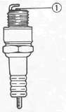
Electrode Gap 1 :
0.7 ~ 0.8 mm (0.028 - 0.031 in)
2. Install spark plug
Spark Plug: 20 Nm (2.0m*kg, 14ft-lb)
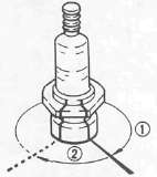
1 Finger tighten
2 Plug wrench tighten
Lighting System
Lighting SystemLIGHTING SYSTEM
3 Main switch
18 Flasher light {Front, Right)
23 Flasher light (Front, Left)
29 Tail/Brake light
31 Fuse "HEAD" (15A)
32 Meter light
33 Head light
34 "HIGH BEAM" indicator light
35 Dimmer switch
36 Starter switch
41 Battery
42 Fuse "MAIN" (30A)
TESTS AND CHECKS Headlight Troubleshooting
|
HEADLIGHT DOES NOT COME ON WHEN ENGINE IS RUNNING/HIGH BEAM DOES NOT OPERATION. |
|
|
|
▼ |
|
|
|
Check headlight. |
Faulty ►
|
Replace.
|
|
▼ |
||
|
Check head fuse. |
Faulty ►
|
Replace.
|
|
▼ |
||
|
Measure voltage on brown wire from main switch ("ON" position). |
Faulty
|
Check dimmer switch, replace if necessary.
|
|
▼ |
||
|
Measure voltage on blue/black wire from starter switch ("ON" position). |
No voltage
|
Check main switch, replace if necessary.
|
|
▼ |
||
|
No voltage
|
Check starter switch, if necessary.
|
|
|
Measure voltage at dimmer switch terminal. |
||
|
▼ |
||
|
An open or poor connection between headlight and dimmer switch terminal. |
||
|
Measure voltage at headlight high beam or low beam terminal. |
No voltage |
|
|
▼ |
|
|
|
|
||
|
Poor ground or poor connection of headlight wiring. |
||
Taillight Troubleshooting
|
TAILLIGHT DOES NOT COME ON WHEN ENGINE IS RUNNING. |
|
|
|
▼ |
|
|
|
Check taillight bulb. |
Faulty |
Replace. |
|
▼ OK |
|
|
Measure voltage on blue wire from main switch ("ON" position). |
No voltage |
Check main switch, replace if necessary. |
|
▼ 12v |
|
|
|
Measure voltage at taillight terminal. |
No voltage. |
An open or poor connection between taillight and main switch terminal. |
|
▼ 12v |
||
|
Poor ground or poor connection or taillight wiring. |
|
|
Signal System
Signal SystemSIGNAL SYSTEM
3 Main switch 10 "FUEL" indicator light 11 Fuel sender 13 Horn
14 Horn switch 15 Flasher relay {Relay assembly) 16 Reed switch
18 Flasher light (Front, Right) 19 Flasher light (Rear, Right)
20 "TURN" indicator light (Right) 21 "TURN" indicator light (Left)
22 Flasher light (Rear, Left) 23 Flasher light (Front, Left) 24 Oil level switch
25 "OIL" indicator light 26 Neutral switch 27 "NEUTRAL" indicator light
28 Brake switch 29 Tail/Brake light 30 Fuse "SIGNAL" 05A)
FLASHER LIGHT Troubleshooting
|
Flasher light and indicator light inoperative. |
||
| ▼ | ||
|
Check bulb. |
Faulty ► |
Replace.
|
|
▼OK |
||
|
Measure voltage at flasher switch (Br/W wire and Y/R wire). |
12V |
Check flasher switch, replace if necessary.
|
|
▼ No voltage |
||
|
Check flasher relay, main fuse, signal fuse and battery. |
Faulty and/or battery discharged . ► |
Replace faulty parts and/or charge battery.
|
|
▼ OK |
||
|
Check reed switch. |
Defect ► |
Replace.
|
|
▼ OK |
||
|
Replace flasher relay (Relay assembly). |
||
FLASHER RELAY (Relay Assembly)
NOTE:
Flasher relay and self cancelling unit are included with relay assembly.
The flasher relay turns off the flashers. Generally the signal will cancel after either 10 seconds of operation or after the motorcycle has traveled 150 meters (490 feet), whichever is greater. At low speed, the cancelling is a function of distance; at high speeds, it's a function of both time and distance.
The flasher switch has three positions: L (left), OFF, and R (right). The switch lever will return to the "OFF" position after being pushed to L or R, but the signal will function. By pushing the lever in, the signal may be cancelled manually.
REED SWITCH
1. Remove:
• Headlight unit
• Headlight body
2. Disconnect the coupler
3. Connect pocket tester
4. Lift the front wheel and rotate the wheel by hand.
5. Measure reed switch resistance
Reed Switch Resistance: About 7 Then return back OΩ or ∞Ω when wheel is stopped
OIL LEVEL INDICATOR LIGHT
1. Troubleshooting
|
Oil level indicator light inoperative |
|||
|
Check bulb |
Faulty |
Replace |
|
|
▼ OK |
|
|
|
|
Measure voltage at oil level switch (Red/Black) |
No voltage |
Check diode, signal fuse, main switch, main fuse, and battery. Replace faulty parts. |
|
|
▼ 12V |
|
|
|
|
Check oil level switch, replace if necessary. |
|
||
Red/Black lead
2 Ground
FUEL WARNING INDICATOR LIGHT
1. Troubleshooting
|
Fuel warning indicator light inoperative |
|||
|
▼ |
|
||
|
Check bulb |
Faulty |
Replace |
|
|
▼ OK |
|
|
|
|
Measure voltage at fuel sender unit (Green). |
No voltage |
Check signal fuse, main switch, main fuse, and battery. Replace faulty parts. |
|
|
▼ 12V |
|
||
|
|
|||
|
Check fuel sender, replace if necessary. |
|
||
1 Green
2 Black
FUEL SENDER UNIT
1. Remove seat
2. Fill the fuel tank (with gasoline)
3. Measure the fuel sender unit resistance.
Fuel Sender Unit Resistance: 1.1 ±0.2kΩ @ 20°C (68°F)
NEUTRAL INDICATOR LIGHT
1. Troubleshooting
|
Neutral indicator light inoperative |
||
|
|
||
|
Check bulb |
Faulty |
Replace
|
|
▼ OK |
||
|
Measure voltage at neutral switch (Sb wire) |
No voltage |
Check signal fuse, main switch, main fuse, and battery, Replace faulty parts. |
|
▼ 12V |
|
|
|
|
||
|
Check neutral switch. Replace if necessary. |
|
|
1 Blue lead
2 Ground
HORN
1. Check:
|
Check for: |
Horn inoperative |
|
12V on brown lead to horn |
|
|
Good ground (horn/pink wire) when horn button is pressed |
|
|
Faulty |
Defective components — Replace.
NOTE:
There are individual fuses for various circuits (See Complete Circuit Diagram)
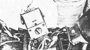
2. Measure the horn resistance
Horn Resistance: 1.05Ω ± 10%
2 Battery (12V)
3. Adjust the volume. Turn the adjuster 1 in and out so that the volume is maximum at the maximum amperage.
|
Tester's lead wire |
Maximum Amperage |
Tester's range |
|
|
Red lead |
Black lead |
||
|
Battery (+) lead |
Horn lead and Battery (-) lead |
2.0A |
DC5A |
BRAKE LIGHT
|
Check for: |
Brake light inoperative |
|
Defective bulb |
|
|
12V on yellow lead to brake light |
|
|
12V on brown lead to each brake light switch (Front and rear brake switch) |
Switches
SwitchesSWITCHES
Use Pocket Tester (90890-03112) on "Ohm x 1" scale to check the switches. Replace any "shorted" or opened element.
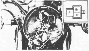
Main Switch
|
Switch position |
Lead color |
||
|
R |
Br |
L |
|
|
ON |
|
|
|
|
OFF |
|
|
|
|
P |
|
|
|


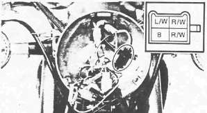
"ENGINE STOP" Switch
|
Switch position |
Lead color |
|
|
R/W |
R/W |
|
|
RUN |
|
|
|
OFF |
|
|


"START" Switch
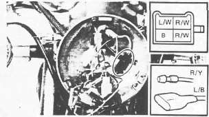
|
Switch position |
Lead color |
|||
|
L/W |
B |
R/Y |
L/B |
|
|
OFF |
|
|
|
|
|
ON |
|
|
|
|


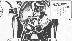
"LIGHTS" (Dimmer) Switch
|
Switch position |
Lead color |
||
|
Y |
L/B |
G |
|
|
HI |
|
|
|
|
LO |
|
|
|


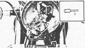
"HORN" Switch
|
Switch position |
Lead color |
|
|
P |
Ground or B |
|
|
PUSH |
|
|
|
OFF |
|
|


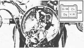
'TURN" Switch
|
Switch position |
Lead color |
|||||
|
Dg |
Br/W |
Ch |
Y/R |
B |
||
|
R |
|
|
|
|
|
|
|
N |
R |
|
|
|
|
|
|
N |
|
|
|
|
|
|
|
L |
|
|
|
|
|
|
|
L |
|
|
|
|
|
|


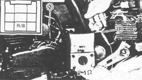
Oil Level Switch
|
Switch position |
Lead color |
|
|
R/B |
Ground |
|
|
ON |
|
|
|
OFF |
|
|


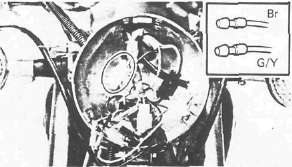
Front Brake Switch
|
Switch position |
Lead color |
|
|
Br |
G/Y |
|
|
ON |
|
|
|
OFF |
|
|


Rear Brake Switch
1 Switch body
2 Adjusting nut
|
Switch position |
Lead color |
|
|
Y |
Y |
|
|
ON |
|
|
|
OFF |
|
|