Cylinder head cover
Place head cover on a surface plate. There should be no warpage. Correct by re-surfacing as follows:
Place # 400 or # 600 grit wet sandpaper on surface plate and re-surface head cover using a figure-eight sanding pattern. Rotate head cover several times to avoid removing too much material from one side.
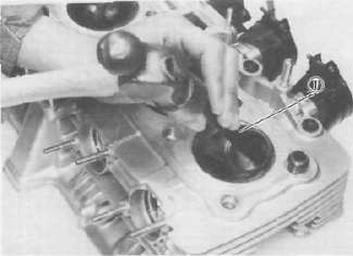
Cylinder head
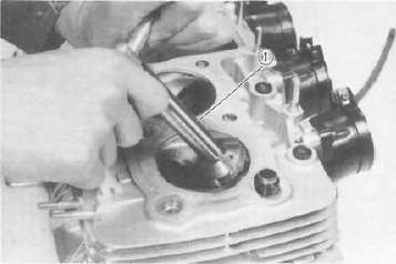
1. Using a rounded scraper, remove carbon deposits from combustion chamber. Take care to avoid damaging spark plug threads and valve seats. Do not use a sharp instrument. Avoid scratching the aluminum.
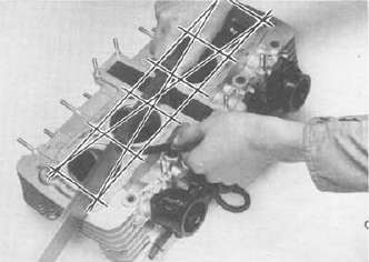
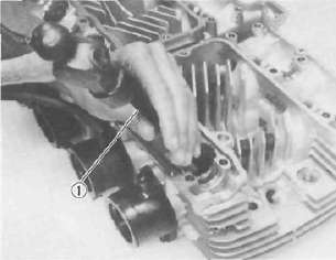
2. Check the cylinder head warpage with a straight edge as shown.
The warpage should not exceed the specified limit, it necessary resurface. If the warpage exceeds allowable limit, the cylinder head should be replaced with a new one.
Cylinder head warpage: less than 0.03 mm (0.0012 in) Allowable limit: 0.25 mm (0.010 in)
Valve, valve guide, and valve seat
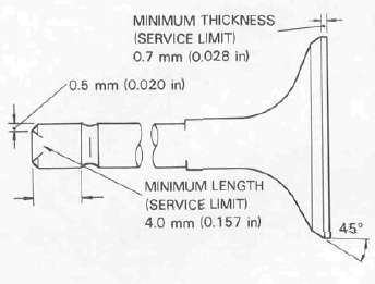
1. Check the valve face and the stem end for wear. If the valve face and/or the stem end are pitted or worn, regrind the valve with a valve refacer. Replace the valve if any dimension exceeds the specifications in the illustration.
INTAKE/EXHAUST VALVE
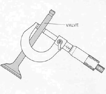
2. Valve stem wear must be measured and then combined with valve guide measurements to guide clearance. This clearance must be within tolerances. If it exceeds the maximum limit, then replace either or both valve and guide, as necessary.
|
|
Valve Stem Clearance |
Maximum |
|
Intake |
0.010 —0.037 mm (0.0004 -0.0015 in) |
0.10 mm (0.004 in) |
|
Exhaust |
0.025 — 0.052 mm (0.0010 -0.0020 in) |
0.12 mm (0.005 in) |

3. Valve stem end
Inspect the end of the valve stem. If the end appears to be ''mushroomed" or has a larger diameter than the rest of the stem, the valve, valve guide, and oil seal should be replaced.
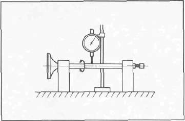
4. Turn valve on "V" blocks and measure the amount of stem runout with a dial gauge. If it exceeds the maximum limit, replace the valve.
Maximum valve stem runout: 0.03 mm (0.0012 in)
5. Valve guide and valve oil seal replacement
If oil leaks into the cylinder through a valve due to a worn valve guide, or if a valve is replaced, the valve guide should also be replaced.
NOTE: The valve oil seal should be replaced whenever a valve is removed or replaced.
a. Measure valve guide inside diameter with a small bore gauge. If it exceeds the limit replace with an oversize valve guide.
Guide diameter (I. D.): Limit: 7.10 mm (0.280 in)
b. To ease guide removal and reinstallation, and to maintain the correct interference fit heat the head to 100 °C (212°F). Use an oven to avoid any possibility of head warpage due to uneven heating.
c. Use the appropriate shouldered punch (special tool) to drive the old guide out and drive the new guide in.
NOTE: When a valve guide is replaced, the 0-ring should also be replaced.
1. Valve guide remover
1. Valve guide installer
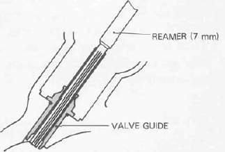
d. After installing the valve guide, use the 7 mm reamer (special tool) to obtain the proper valve guide to valve stem clearance.
e. After installing the valve guide in the cylinder head, the valve seat must be recut. The valve should be lapped to the new seat.
6. Grinding the valve seat a. The valve seat is subject to severe wear. Whenever the valve is replaced or the valve face is re-surfaced (see CAUTION) the valve seat should be re-surfaced at a 45° angle. If a new valve guide has been installed the valve seat must be recut to guarantee complete sealing between the valve face and seat.
Remove just enough material to achieve a satisfactory seat.
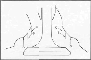
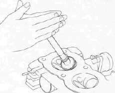
CAUTION: If the vatve seat is obviously pitted or worn, it should be cleaned with a valve seat cutter. Use the 45° cutter, and when twisting the cutter, keep an even downward pressure to prevent chatter marks.
If cutting section "A" of the valve seat, use 30° cutter. If cutting section "B", use the 45° cutter. If cutting section "C", use 60° cutter. b. Measure valve seat width. Apply mechanic's bluing dye (such as Dykem) to the valve face and valve seat, apply a very small amount of fine grinding compound around the surface of the valve face insert the valve into position, and spin the valve quickly back and forth. Lift the valve, clean off all grinding compound, and check valve seat width. The valve seat and valve face will have removed bluing wherever they contacted each other. Measure the seat width with vernier calipers. It should measure approximately 0.9 — 1.1 mm (0.035 — 0.043 in). Also, the seat should be uniform in contact area. If valve seat width varies, or if pits still exist, further cutting will be necessary.
|
|
Standard Width |
Wear Limit |
|
Seat width |
0.9 —1.1 mm (0.035 -0.043 in) |
2.0 mm (0.080 in) |

c. If the valve seat is uniform around the perimeter of the valve face, but is too wide or not centered on the valve face, it must be altered. Use either the 30°, 45° or 60° cutters to correct the improper seat location in the manner described below:
1) If the valve face shows that the valve seat is centered on the valve face, but too wide, then lightly use both the 30° and the 60° cutters to reduce the seat width to 0.9 —1.1 mm (0.035 —0.043 in).

2) If the seat shows to be in the middle of the valve face, but too narrow, use the 45° cutter until the width equals 0.9 ~~ 1.1 mm (0.035 —0.043 in).
1. Valve seat cutter
3) If the seat is too narrow and right up near the valve margin, then first use the 30° cutter and then the 45° cutter to get the correct seat width.
4) If the seat is too narrow and down near the bottom edge of the valve face, then first use the 60° cutter and then the 45° cutter.
7. Lapping the valve/valve seat assembly
a. The valve/valve seat assembly should be lapped if neither the seat nor the valve face are severely worn.
b. Apply a small amount of coarse lapping compound to valve face. Insert the valve into the head. Rotate the valve until the valve and valve seat are evenly polished. Clean off the coarse compound, then follow the same procedure with fine compound.
Continue lapping until the valve face shows a complete and smooth surface all the way around. Clean off the compound material. Apply bluing dye to the valve face and seat and rotate the valve face for full seat contact which is indicated by a grey surface all around the valve face where the bluing has been urbbed away.
c. Valve leakage check
After all work has been on the valve and valve seat, and all head parts have been assembled, check for proper valve/valve seat sealing by pouring solvent into each of the intake ports, then the exhaust ports. There should be no leakage past the seat. If fluid leaks, disassemble and continue to lap with fine lapping compound. Clean all parts thoroughly, reassemble and check again with solvent. Repeat this procedure as often as necessary to obtain a satisfactory seal.
Valve spring and lifters

| 6 | Adjusting Pad |
10. |
Inner spring |
|
7 |
Valve Lifter |
11. |
Outer spring |
|
8. |
Valve Retainer | 12 | Oil Seal |
|
9 |
Spring Seat | 13. | Valve |
1. Checking the valve springs
a. This engine uses two springs of different sizes to prevent valve float or surging. The valve spring specifications show the basic value characteristics.
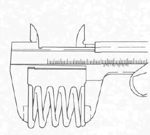
b. Even though the spring is constructed of durable spring steel, it gradually loses some of it's tension. This is evidenced by a gradual shortening of free length. Use a vernier caliper to measure spring free length. If the free length of any spring has decreased more than 2 mm (0.080 in) from its specification replace it
c. Another symptom of a fatigued spring is insufficient spring pressure when compressed. This can be checked using a valve spring compression rate gauge. Test each spring individually. Place it in the gauge and compress the spring first to the specified compressed length with the valve closed (all spring specifications can be found in the previous section, Valve spring), then to the length with the valve open. Note the poundage indicated on the scale at each setting. Use this procedure with the outer springs, then the inner springs.
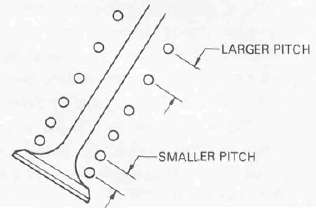
NOTE: All valve springs must be installed with larger pitch upward as shown.
|
Valve Spring Specifications |
||
|
OUTER |
INNER |
|
|
Free length |
39.5 mm (1.555 in) |
35.9 mm (1.413 in) |
|
Installed length (valve closed) |
34.0 mm (1.339 in) |
31.0 mm (1.220 in) |
|
Installed pressure |
17.6 -20.6 kg (38.8 - 45.4 lb) |
8.1 -9.9 kg (17.9 -21.8 lb) |
|
Allowable tilt from vertical |
2.5° |
— |
2. Valve lifter a. Check each valve lifter for scratches or other damage. If the lifter is damaged in any way, the cylinder head surface in which it rides is probably also damaged. If the damage is severe, it may be necessary to replace both the lifter and the cylinder head.
NOTE: For proper valve lifter-to-head clearance, always install lifters on their original valves.
Camshafts, cam chain and cam sprockets
1. Camshaft
a. The cam lobe metal surface may have a blue discoloration due to excessive friction. The metal surface could also start to flake off or become pitted.
b. If any of the above wear conditions are readily visible, the camshaft should be replaced.
c. Even though the cam lobe surface appears to be in satisfactory condition, the lobes should be measured with a micrometer. Cam lobe wear can occur without scarring the surface. If this wear exceeds a pre-determined amount, valve timing and lift are affected. Replace the camshaft if wear exceeds the limits.
d. Install the camshaft on the cylinder head. Place a strip of Plastigage between camshaft and camshaft cap as illustrated (lengthwise along camshaft). Tighten the nuts with specified torque. Remove the camshaft cap and determine the clearance by measuring the width of the flattened Plastigage.
Cap nut tightening torque: 10 Nm (1.0 rrvkg, 7.2 ft lb)
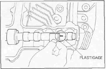
NOTE: Do not turn camshaft when measuring clearance with plastigage.
Camshaft-to-cap clearance:
Standard: 0.020 — 0.054 mm
(0.0008 —0.0021 in) Maximum: 0.160 mm (0.006 in)
If the camshaft-to-cap clearance exceeds specification, measure camshaft bearing surface diameter.
Bearing surface diameter: Standard: 24.967 — 24.980 mm (0.9830 - 0.9835 in)
1) If the camshaft diameter is less than specification, causing excessive clearance, replace the camshaft.
2) If the camshaft is within specificaton and camshaft-to-cap clearance is excessive, replace the cylinder head.
2. Cam chain
Except in cases of oil starvation, the cam chain wears very little. If the cam chain has stretched excessively and it is difficult to keep the proper cam chain tension, the chain should be replaced.
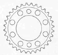
3. Cam sprockets
Check cam sprockets for obvious wear.
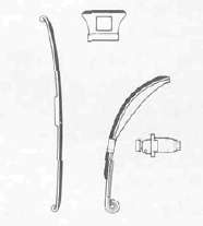
4. Cam chain dampers and tensioner
Inspect the top cam chain damper (stopper guide) and two (2) vertical (slipper-type) dampers for excessive wear. Any that shows excessive wear should be replaced. Worn dampers may indicate an improperly adjusted or worn-out cam chain.
Cylinder
1. Inspect the cylinder walls for scratches. If vertical scratches are evident, the cylinder wall should be rebored or the cylinder should be replaced.
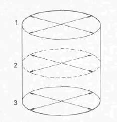
2. Measure cylinder wall wear as shown. If wear is excessive, compression pressure will decrease. Rebore the cylinder wall and replace the piston and piston rings. Cylinder wear should be measured at three depths with a cylinder bore gauge. (See illustation.)
|
|
Standard |
Wear Limit |
|
Cylinder bore |
67.00 mm (2.638 in) |
67.10 mm (2.642 in) |
|
Cylinder taper |
- |
0.05 mm (0.002 in) |
|
Cylinder out-of-round |
- |
0.01 mm (0.0004 in) |
If the cylinder wall is worn more than the wear limit, it should be rebored.
- Printer-friendly version
- Log in to post comments