Problem: HEADLIGHT DOES NOT COME ON. (MONITOR DOES NOT LIGHT.)
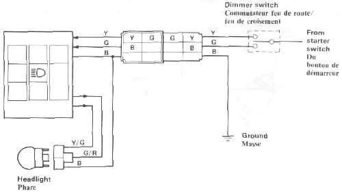
Light lead connections:
HI: Yellow to Yellow/Green (or Yellow/Red)
Lo: Green to Green/Red
NOTE: On the XJ750, no lights will come on before the engine starts.
|
Disconnect the 3-P coupler (for headlight) in the headlight body, and check voltage. |
12V ► |
Headlight bulb is burnt out. |
| Less than 12V ▼ | ||
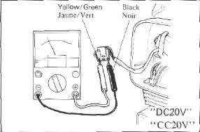
| Measure input voltage on the wire harness side through the 6-P coupler in the headlight body. Hi: Yellow to Ground Lo: Green to Ground 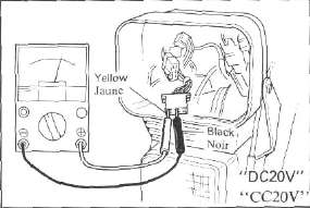 • • |
Reads 12V ► |
• CMS is faulty |
| Less than 12V ▼ | ||
|
• Dimmer switch Check the condition of these parts according to the electrical section of the service manual. |
Problem: HEADLIGHT COMES ON AND MONITOR WILL NOT GO OFF.
• CMS is faulty.
• LCD is faulty.
• Connector is faulty.
NOTE: If the monitor (HEAD) comes on with the main switch turned on, both LCD and connector are in good condition. Replace CMS.
Problem: THE HEADLIGHT BULB IS NOT BURNT OUT, BUT THE MONITOR COMES ON.
• Yellow/Green lead is broken.
• Green/Red lead is broken.
• Black lead is broken.
• Connector is loose.
TAIL/BRAKE LIGHT DOES NOT COME ON. (MONITOR DOES NOT COME ON.)
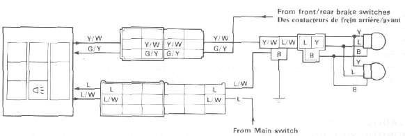
Light lead connections:
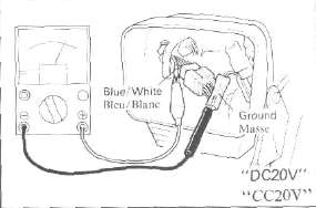
Tail: Blue-Blue/White
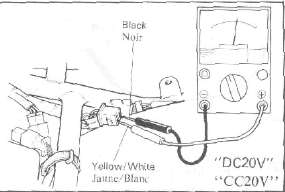
Brake: Green/Yellow- Yellow/White (or Yellow/Black)
|
Disconnect the 3-P coupler of the taillight, and measure voltage. |
12V ► |
• Burnt taillight bulb
|
|
Less than 12V ▼ |
||
|
Disconnect the Y/W and L/W leads from the monitor side of the 6-P and 9-P couplers, and check voltage. |
12V |
• Broken Yellow/White lead
|
|
Less than 12V ▼ |
|
|
| Measure voltage of the L lead and G/Y lead on the wire harness side. Tail: Blue lead from Main switch Brake: Green/Yellow lead from brake switches 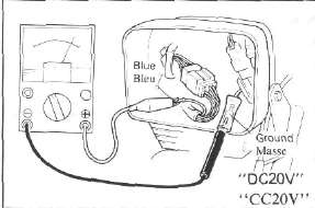 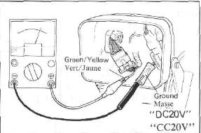 |
12V ► |
• CMS is faulty. |
| Less than 12V ▼ | ||
|
• Brake: Check the brake switch and leads. |
|
|
EXAMPLES OF OTHER TROUBLES
The computerized monitor system may malfunction under the following conditions, though it is in good condition. The term "malfunction" means an erratic change in the display when the computerized monitor is not operated.
1. The battery is in a state of extremely low voltage. The computerized monitor system is so designed that it operates normally when a specific voltage is input. Therefore, if the battery has almost run down or sulfation, the system may malfunction.
2. The computerized monitor system is interfered by radio noise. The system has a protective device against radio noise, but some special radio noise may cause the system to malfunction.
Radio noise can be produced in the following cases:
a. When spark plugs without resistor are used on an engine for which spark plugs with built-in resistor should be used.
b. When a special horn is used.
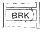
EXAMPLES OF ERRATIC LC. DISPLAYS
If any one of the following symptoms appears, the L.C. display is considered to be faulty.
1. Part of the L.C. display is chipped off.
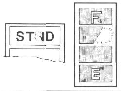
2. The deflecting plate has scratches or cavities.
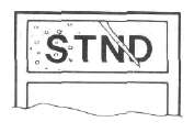
3. Glass is cracked or chipped,
4. Contrast is uneven on the same display.
- Printer-friendly version
- Log in to post comments