ELECTRIC STARTING SYSTEM
STARTING CIRCUIT OPERATION
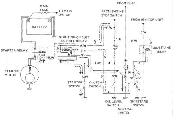
The starting circuit on this model consists of the starter motor, starter relay, and the starting-circuit cut-off relay. If the engine stop switch and the main switch are both on, the starter motor can operate only if:
a. The transmission is in neutral (the neutral switch is on).
or if
b. The clutch lever is pulled to the handlebar (the clutch switch is on) and the sidestand is up (the sidestand switch is on).
The starting-circuit cut-off relay prevents the starter from operating when neither of these conditions has been met. In this instance, the starting-circuit cut-off relay is off so current cannot reach the starter motor. When one or both of the above conditions have been met, however, the starting-circuit cut-off relay is on, and the engine can be started by pressing the starter switch.
A. Sidestand Relay
The sidestand relay operates by shorting the TCI control current. When the sidestand is down, the sidestand relay is closed, and the TCI control current is grounded through the sidestand relay. Thus, the engine will not run with the sidestand down unless the transmission is in neutral.
|
|
WHEN THE TRANSMISSION IS IN NEUTRAL. |
|
|
WHEN THE CLUTCH LEVER IS PULLED TO THE HANDLEBAR AND THE SIDESTAND IS UP. |


B. Starter Motor
1. Removal (see CHAPTER 3. "ENGINE DISASSEMBLY")
2. Inspection and repair
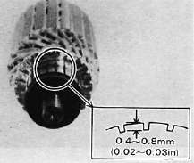
a. Check the outer surface of the commutator. If its surface is dirty, clean with # 600 grit sand paper.
b. The mica insulation between commutator segments should be 0.4 ~ 0.8 mm (0.02 ~ 0.03 in) below the segment level. If not, scrape to proper limits with appropriately shaped tool. (A hack saw blade can be ground to fit.)
NOTE:
Mica insulation of commutator must be undercut to ensure proper operation of commutator.
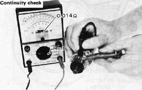
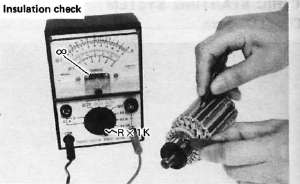
c. The starter's armature coil should be checked with an ohm meter for insulation breakdown (shorting to each other or to ground) and for continuity. Reference figure is given below.
Coil resistance: Armature coil: 0.014Ω at 20°C (68°F)
d. Check the front and rear cover bearings for damage. If damaged, the starter assembly must be replaced.
e. Check brush length. Replace brush if at, or near, limits.
Minimum brush length: 8.5 mm (0.33 in)
f. Check brush spring pressure. Compare it with a new spring. Replace the old spring if it is weak.
C. Starter Relay Switch
1. Inspection
a. Disconnect starter cable at the relay.
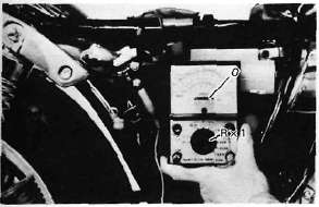
b. Connect pocket tester leads to the relay terminals (ohms x 1 scale).
c. Turn ignition to "ON" position, engine stop switch to "RUN" and change lever to "NEUTRAL".
d. Push the starter button. The relay should click once and the scale should read zero if it does not read zero, the relay must be replaced.
1. Battery lead wire (+)
2. Starter motor lead wire
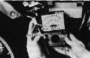
e. If the relay does not click, check the wires from the starter button and from the battery (red/white, blue/white). Turn the ignition off. Use (ohms x 1) scale on tester. The resistance between these wires should be no more than 3.5Ω. If there is more resistance, the relay should be replaced.
- Printer-friendly version
- Log in to post comments