SHAFT DRIVE
Refer to "CHAPTER 3". for the middle gear.
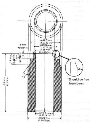
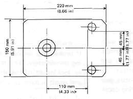
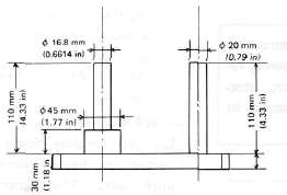
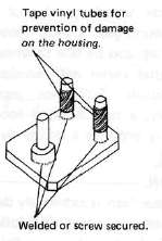
The following special tools are not available but can be constructed for the final gear disassembly and assembly:

A. Troubleshooting
1. The following conditions may indicate damaged shaft drive components:
|
Symptoms |
Possible damaged areas |
|
1. A pronounced hesitation or "jerky" movement during acceleration, deceleration, or sustained speed. (This must not be confused with engine surging or transmission characteristics). 2. A "rolling rumble" noticeable at low speed; a high-pitched whine; a "clunk" from a shaft drive component or area. |
A. Damage to bearings. B. Improper gear lash. C. Gear tooth damage. D. Drive flange/universal joint bolts loose. |
|
3. A locked-up condition of the shaft drive mechanism; no power transmitted from engine to rear wheel. |
E. Broken drive-shaft. F. Disconnected flange/universal joint connection. G. Broken gear teeth. H. Seizure due to lack of lubrication. I. Small foreign object lodged between moving parts. |
Note:
Damage areas A, B, and C above may be extremely difficult to diagnose. The symptoms are quite subtle and difficult to distinguish from normal motorcycle operating noise. If there is reason to believe component(s) are damaged, remove component(s) for specific inspection.
2. Inspection Notes:
a. During coasting, accelerating or decelerating, the "rolling rumble" will increase with rear wheel speed, not engine or transmission gear speeds. However, such noise may also be due to wheel bearings.
b. Noise that varies with acceleration and deceleration: Following incorrect reassembly, a condition of too-little gear lash may produce a whine during deceleration.
CAUTION:
Too-little gear lash is extremely destructive to gear teeth. If a test ride following reassembly indicates this condition, stop riding immediately to minimize damage to gears.
c. A slight "thunk" must be distinguished from normal motorcycle operation. It will be most noticeable at low speed and could indicate broken gear teeth.
WARNING:
If broken gear teeth are suspected, stop riding immediately. This condition could lead to locking-up of the shaft drive assembly and result in harm to a rider.
d. If the drive flange/universal joint bolts are slightly loose, a "clunk" may be felt when slowly taking off, or when changing from slow acceleration to slow deceleration. At high speed this will result in vibration.
WARNING:
Do not continue riding a motorcycle suspected of having loose flange/universal joint bolts. The components may break, causing injury to a rider.
3. Troubleshooting Chart
Where Basic Conditions "a" and "b" above exist, consider the following Chart:
|
Elevate and spin front wheel. Feel for wheel bearing damage. |
Yes ► |
Replace wheel bearing. (See CHAPTER 5 "Front wheel") |
|
|
||
|
Check rear wheel. Feel for bearing damage. |
No ►
|
Rear wheel bearings and shaft drive bearings probably not damaged. Repeat test or remove individual components. |
|
|
||
|
Remove rear wheel. Check for wheel bearing damage. |
Yes ► |
Replace rear wheel bearing. (See "Rear Wheel" section in this chapter.) |
|
|
||
|
Remove drive shaft components. |
4. Oil Leak Inspection
If a shaft drive component is suspected of leaking oil, first thoroughly clean the entire motorcycle. The apparent location of an oil leak on a dusty motorcycle may be misleading. Dry the motorcycle and apply a leak-localizing compound or a dry-powder spray that will limit the flow of any leaking oil. Operate the motorcycle prepared in this way for the distance necessary to precisely locate the leak. There are the possibilities that a component housing may have been damaged by road debris or an accident, or a gasket or seal may be cracked or broken. However, on new or nearly new motorcycle an apparent oil leak may be the result of a rust-preventive coating or excess assembly lubrication of seals. Always clean the motorcycle and recheck the suspected location of any apparent leakage.
5. Checking Drained Oil
Whenever a problem is suspected in either the middle or final gear assemblies, drain and inspect the oil. Metal particles on the drain plug or in the oil could indicate a bearing seizure or other problem in the component. However, a small amount of metal particles in the oil is normal.
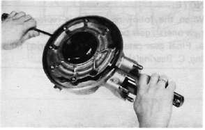
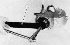
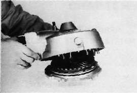
B. Final Gear Removal
1. Remove:
• Rear axle
• Rear wheel (see "Rear Wheel" section in this chapter).
• Left shock absorber
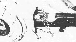
• Nut 1
• Final gear assembly 2
2. Remove the 4 nuts holding the Final Drive unit to the swing arm.
3. Remove the final gear assembly.
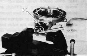
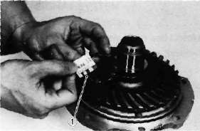
C. Gear Lash Check and Adjustment
1. Secure the gear case in a vice or other support.
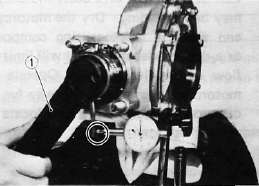
2. Remove one nut from the final gear case stud bolt. Install the gear holder (special tool) over the ring gear surface and stud bolt. Tighten the holder to stud bolt with a nut.
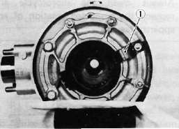
1. Final gear holding tool
3. Install the final gear lash measurement tool on the gear coupling.
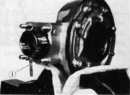
1. Gear lash measurement tool (Final gear)
4. Mount a dial gauge against the lash measurement tool at the scribed mark (60 mm, 2.36 in from the center of the shaft).
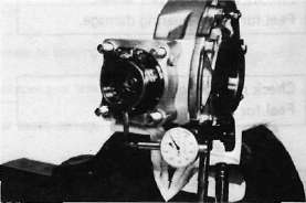
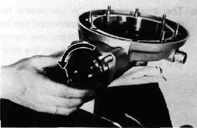
5. Use the special wrench to gently rotate the gear coupling back and forth. Note the lash measurement on the dial gauge.
Final gear lash:
When using the measurement tool: 0.25 - 0.50 mm (0.010-0.020 in) .
Actual gear lash on the final gear teeth: 0.1 ~ 0.2 mm (0.004 ~ 0.008 in).
1. Middle and final gear holding tool
6. If the gear lash exceeds the specified limits, adjust as follows:
a. To reduce gear lash, increase the ring gear shim.
b. To increase gear lash, reduce ring gear shim.
1. Ring gear shim
c. If it is necessary to increase the ring gear shim by more than 0.1 mm reduce the thrust washer thickness by 0.1 mm for each 0.1 mm of ring gear shim increase and if it is necessary to reduce shim by more than 0.1 mm, reverse above procedure.
D. Final Gear Disassembly
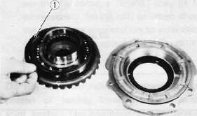
1. Remove the nuts and bolts holding the bearing housing.
2. Remove the ring gear assembly and thrust washer from the final gear case.
3. Remove the self-locking nut from drive pinion by using the holding tool (special tool) and remove the coupling.
1. Middle and final gear holding tool
4. Remove the drive pinion bearing retainer with the retainer remover (special tool).
CAUTION:
The drive pinion bearing retainer nut is left hand threads. Turn the retainer nut clockwise to loosen.
1. Drive pinion bearing retainer remover
5. Remove the drive pinion and bearing with the slide hammer and adapter (special tool).
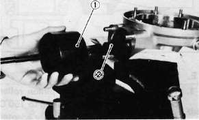
1. Slide hammer 2. Adapter
CAUTION:
This drive pinion removal should be performed only if gearing replacement is necessary. Do not re-use bearings or races after removal.
6. Remove the guide collar, oil seal, and roller bearing from the main housing by using the press tool No. 1 (special tool) and a press. Use an appropriate supports for the main housing during this operation. The roller bearing may be re-used if undamaged. Do not re-use oil seal.
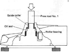
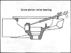
Rear drive pinion roller bearing; removal of this bearing is difficult and seldom necessary. Heat the bare housing to 150°C (302°F). Use an appropriately shaped punch to remove the roller bearing outer race. Remove the inner race from the drive pinion.
E. Final Gear Reassembly
1. Install the new rear drive pinion roller bearing. Heat the bare bearing to 150°C (302°F) and use an appropriately adapter to install the roller bearing outer race. Install the inner race onto the drive pinion.
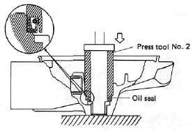
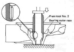
2. Using the press tool No. 2 (special tool) and a press, install the guide collet, new oil seal, and roller bearing into the main housing in that order.
NOTE:
The removed roller bearing can be used if undamaged; however, we recommend replacement with a new one.
3. Final drive/ring gear positioning
NOTE:
When the following part(s) is replaced with new one(s), gear positioning is necessary: a. Final gear case, b. Ring gear bearing housing, C. Bearing(s)
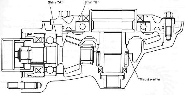
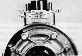
a. The shim thickness "A" necessary for the drive pinion gear positioning can be calculated from the information found on the final gear case and on the drive gear end.
1. Size number
To fined shim thickness "A" use the
formula:
A = a -b
Where:
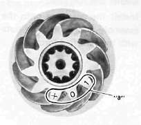
a = a numeral (usually a decimal number) on the gear near the tooth and either added to or detracted from the nominal size "84".
b = a numeral on the gear case appearing as a whole figure (ie. 83.50).
Example:
1) If the pinion gear is marked "+01"....."a" is 84.01.
2) If the gear case is marked "83.50".
A = 84.01 - 83.50 A = 0.51
Then the necessary shim thickness is 0.51mm.
Shim sizes are supplied in the following thicknesses:
0.15 mm, 0.30 mm, 0.40 mm, 0.50 mm, 0.60 mm.
Because the shims can only be selected in 0.05 mm increments the following chart should be used when encountering last digits that are not 5 or zero (0):
|
Last digits |
Rounding |
|
0,1,2 |
0 |
|
3, 4, 5, 6, 7 |
5 |
|
8,9 |
10 |
b. The shim thickness "B" necessary for the ring gear positioning can be calculated from the information found on the final gear case, ring gear, and bearing.
To find shim, thickness "B" use the
formula:
B = c + d-(e + f)
Where:
c= a numeral on the gear case appearing as a whole figure (ie. 45.52)
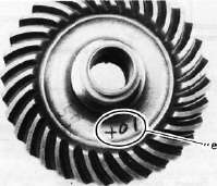
d = a numeral (usually a decimal number) on the outside of the ring gear bearing housing and added to the nominal size "3".
e= a numeral (usually a decimal number) on the inside of the ring gear and; either added to or detracted from the nominal size "35.40".
f = a bearing thickness (considered constant)
Distance "f" = 13.00 mm
Example:
1) If the gear case is marked "45.52".
2) If the ring gear bearing housing is marked "35"....."d" is 3.35.
3) If the ring gear is marked "+01" ..... "e" is 35.40 + 0.01 = 35.41.
4) "f" is 13.00.
B = c + d-(e + f)
B = 45.52 + 3.35 - (35.41 + 13.00)
B = 48.87- (48.41)
B = 0.46
Then the necessary shim thickness is
0.41 mm.
NOTE:
Use the chart for the drive pinion shim to select the ring gear shim size.
4. Install the drive pinion gear with the proper size of shim(s) and secure it with the bearing retainer nut with the drive pinion bearing retainer remover (special tool).
NOTE:
The bearing retainer nut is left hand threads; turn the nut to counterclockwise to tighten.
Tightening torque: 11 m-kg (80 ft-lb)
Install the ring gear assembly without the thrust washer. Adjust the gear lash (refer to "C. Gear lash check and adjustment).
Place four pieces of "PLASTIGAGE" between the originally fitted thrust washer and ring gear. Install the gear case onto the ring gear assembly and tighten the nuts and bolts with the specified torque.
Tightening torque;
Bolt/Nut......... 2.3 m-kg
(16.6 ft-lb)
NOTE:
Do not turn the drive pinion/ring gear when measuring clearance with "PLASTIGAGE".
8. Remove the ring gear assembly and determine the clearance by measuring the width of the flattened "PLASTIGAGE".
1. PLASTIGAGE
Ring gear thrust clearance. 0.1 ~ 0.2 mm
9. If the clearance exceeds the specification above, replace the thrust washer to obtain the proper clearance.
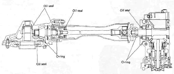
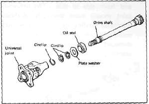
DRIVE SHAFT/JOINT
A. Removal
1. Remove the rear wheel. See "REAR WHEEL A. Removal" in this chapter.
2. Remove the final gear case assembly.
3. Remove the drive shaft. See "SWING ARM removal" in this chapter.
4. To remove the universal joint, it is necessary to remove the swing arm. Remove the universal joint assembly.
B, Inspection
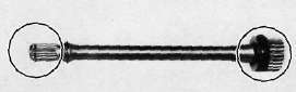
1. Drive shaft
Inspect the shaft splines for wear and/or damage. If excessive, replace the drive shaft.
NOTE:
When installing the drive shaft, lubricate splines with molybdenum di-sulfide grease.
2. Universal joint
a. There should be no noticeable play in the universal joint bearings. If there is any play in the bearing, replace the universal joint assembly.
b. Move the universal joint up and down and from side to side. The universal joint should move smoothly. Without tightness, binding or rough spots that could indicate damaged bearings. If damaged, replace the universal joint assembly.
C. Reinstallation
When installing the drive shaft and the universal joint, reverse the removal procedure. Note the following points:
1. Lubricate the shaft splines with molybdenum di-sulfide grease.
2. Tighten the universal joint securing bolts and final gear case securing nuts with the specified torque:
Final gear case: 4.2 m-kg (30.4 ft-lb) Universal joint: 4.4 m-kg (31.8 ft-lb)
- Printer-friendly version
- Log in to post comments