CRANKSHAFT/PISTON
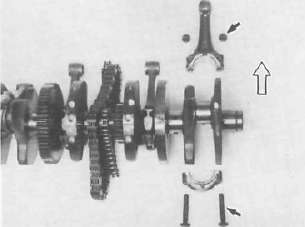
. WHEN INSTALLING THE CONNECTING ROD. BE SURE THAT THE SECURING NUTS ARE ON TOP.
Engine assembly
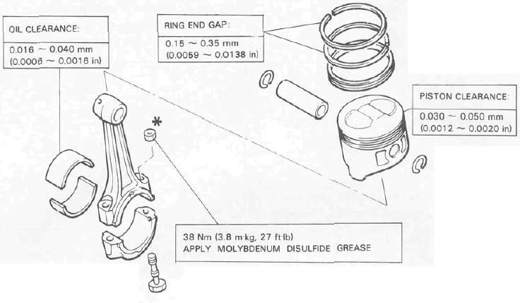
1. Upper crankcase a. Install the connecting rods onto the crankshaft with the proper connecting rod bearings and apply molybedenum disulfide grease to the bolt threads. Apply torque evenly to both ends of the cap.
CAUTION: While tightening, if a torque of 38 Nm (3.8 mkg, 27 ft-lb) or more is reached, DO NOT STOP tightening until final torque is reached.
If tightening is interrupted between 35 Nm (3.5 mkg, 25 ft-lb) and 41 Nm (4.1 mkg, 30 ft-lb), loosen the nut to less than 30 Nm (3.0 mkg, 22 ft-lb) and start again. Tighten to full torque specification without pausing.
CAUTION: When installing the connecting rod, be sure that the securing nuts are on top. Otherwise, engine damage will result.
Rod cap torque: 38 Nm (3.8 mkg, 27 ft-lb)
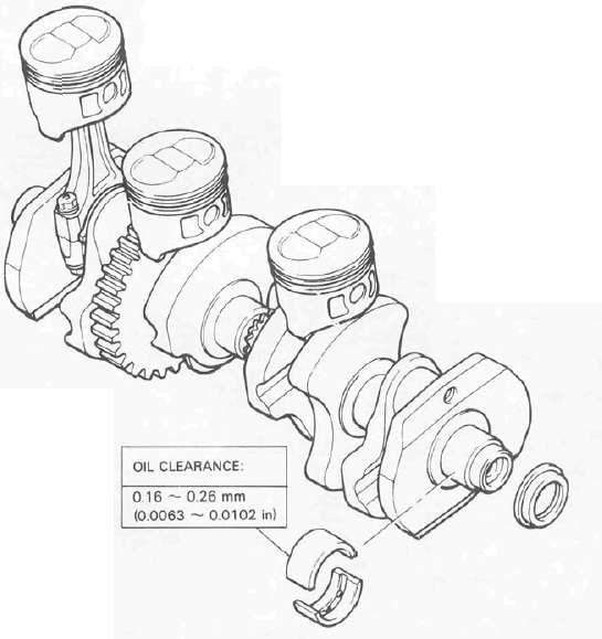
b. Install the proper crankshaft main bearings into the crankcase and place the crankshaft. Oil the bearings liberaly.
NOTE: Do not forget to install the crankshaft oil seal (L.H.), blind plug (R.H.), "HY-VO" chain and cam chain on the crankshaft before installing. Also, install the chain guide into upper crankcase if removed.
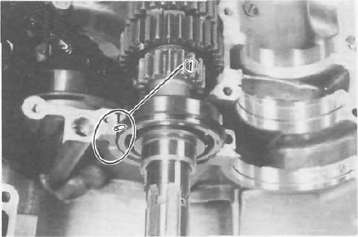
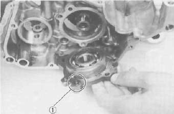
c. Install the starter idle gear, shaft, stopper plate, and new lock plate. Tighten the bolt securely and bend the lock tabs along the bolt flats.
Tightening torque:
10 Nm (1.0 mkg, 7.2 ft-lb)
1, Lock washer
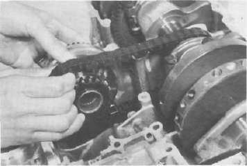
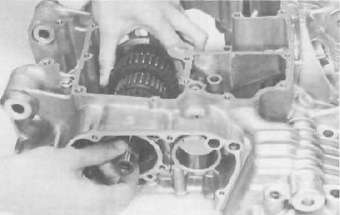
d. Put the starter clutch and sprocket assembly in the "HY-VO" chain and lay it into the crankcase.
e. Install the A.C.G. Generator shaft into the starter clutch assembly.
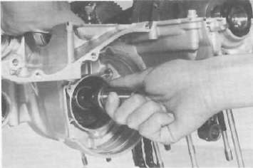
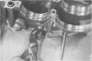
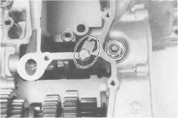
f. Install the "HY-VO" chain oil spray nozzle. The locating pin on the nozzle should be placed into the crankcase locating slot. Do not forget to install the new "O-ring" onto the nozzle.
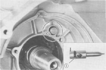
1. O-ring
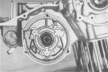
g. Install the new "O-ring" onto the bearing housing and install it with the panhead screw.
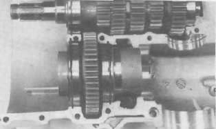
h. Install the transmission main axle assembly on the upper crankcase. Point the bearing locating pin toward the crankshaft and lay it on the case.
1. Bearing locating pin
i. Install the middle driven gear (without the middle drive pinion gear).
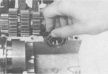
j. Install the middle driven gear shaft end bearing.
k. Install the dowel pin with "O-ring" into the crankcase.
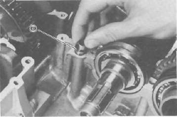
1. O-ring
2. Lower crankcase a. Install the transmission drive axle assembly into the crankcase.
b. Install the 5th wheel gear and bearing onto the drive axle. Install the bearing cover. Be sure the "O-ring" is on the cover.
1. O-ring
c. Install the shift cam and secure it with the guide pin. Install the stopper plate and bolt and tighten securely.
d. Install the neutral switch.
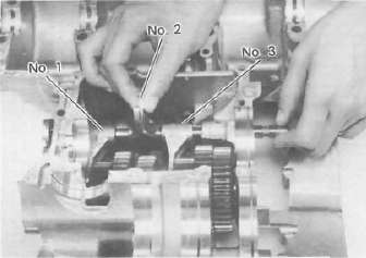
e. Install the shift forks and guide bar. Each shift fork is identified by a number cast on its side. All the numbers should face the left side and numbered 1, 2, and 3 from left.
- Printer-friendly version
- Log in to post comments