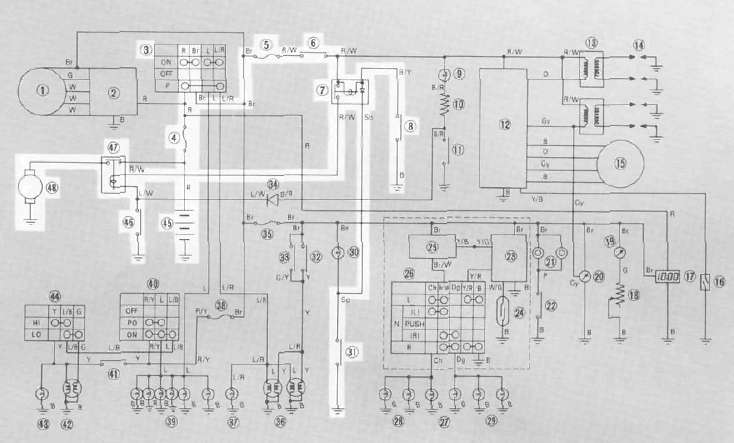
Circuit diagram
Starter motor
1. Removal
See Engine Dissassembly, Starter and Generator.
2. Inspection and repair
a. Check the outer surface of the commutator. If its surface is dirty, clean with # 600 grit sand paper.
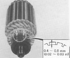
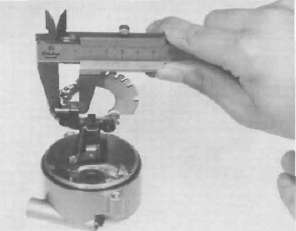
b. The mica insulation between commutator segments should be 0.4 — 0.8 mrn (0.02 — 0.03in) below the segment level. If not, scrape to proper limits with appropriately shaped tool. (A hack saw blade can be ground to fit.)
NOTE: Mica insulation of commutator must be undercut to ensure proper operation of commutator.
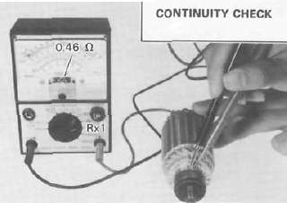
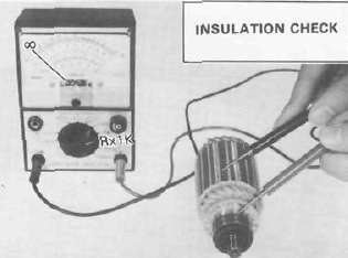
c. The starter's armature coil should be checked with an ohm meter for insulation breakdown (shorting to each other or to ground) and for continuity. Reference figure is given below.
Coil resistanec: Armature coil: 0.014 Ω ± 6 % at 20°C (68°F)
d. Check the front and rear cover bearings for damage. If damaged, the starter assembly must be replaced.
e. Check brush length. Replace brush if at or near, limits.
Minimum brush length: 8.5 mm (0.33 in)
f. Check brush spring pressure. Compare it with a new spring. Replace the old spring if it is weak.
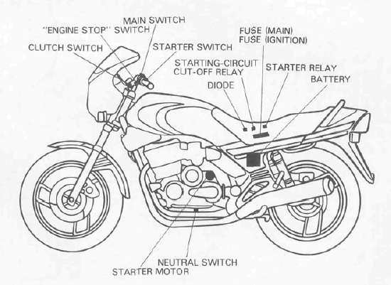
Starter relay
1. Inspection
a. Disconnect starter relay leads at the relay.
b. Connect pocket tester leads to the relay terminals (ohms x 1 scale).
c. Turn ignition to "ON" position, engine stop switch to "RUN" and change lever to "NEUTRAL".
d. Push the starter switch. The relay should click once and the scale should read zero if it does not read zero, the relay must be replaced.
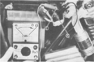
1 Battery lead (+) 2. Starter motor lead
e. If the relay does not click, check the leads from the starter switch and from the battery (white/red, blue/white). Turn the ignition off. Use (ohms x 1) scale on tester. The resistance between these leads should be no more than 3.4 ohms. If there is more resistance, the relay should be replaced.
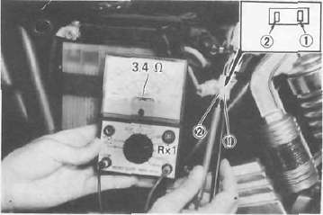
1 Blue/White 2 White/Red
Starting-circuit cut-off relay
1. Inspection
a. Remove the seat.
b. Remove the starting-circuit cut-off relay from the electrical components holding plate, and disconnect the connector.
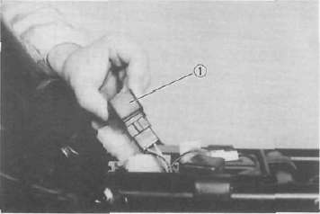
1 Starting-circuit cut-off relay
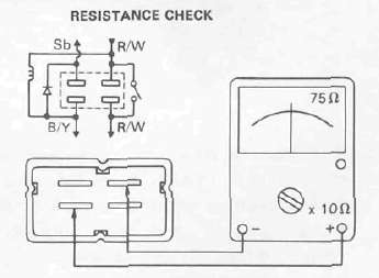
c. Check the resistance of the relay coil windings with the pocket tester. If the resistance is not within specification, replace the relay.
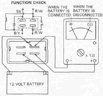
d. Check the relay function with a 12 volt battery and the pocket tester. Connect the leads as shown in the illustration. If the resistance readings do not equal those shown in the illustration, replace the relay.
Neutral switch
Diode
1. Inspection
a. Remove the seat.
b. Remove the diode from the electrical components holding plate, and disconnect the connector.
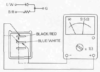
c. Check the resistance of the diode with the pocket poster as shown in the illustration. If the resistance is not specification, replace the diode.
NOTE: Only the Yamaha Pocket Tester will give a 9.5 Ωreading when testing continuity. The particular characteristics of other testers will vary the continuity test readings.
1. Inspection
a. Remove the seat.
b. Disconnect the 4-pin connector from the main wire harness.
c. Connect the pocket tester leads as shown, and set the tester selector to ohm x 1.
When the transmission is in neutral, the tester should read zero ohms. When the transmission is in gear, the tester should read infinity.
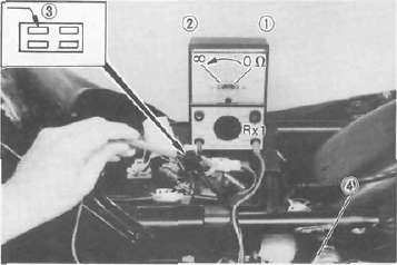
1. Neutral 2 In gear 3. Sky blue 4 Ground
Clutch switch
1. Inspection
a. Remove the seat.
b. Disconnect the 4-pin connector from the main wire harness.
c. Connect the pocket tester leads as shown, and set the tester slector to ohm x 1.
When the clutch is disengaged, the tester should read zero ohms. When the clutch is engaged, the tester should read infinity.
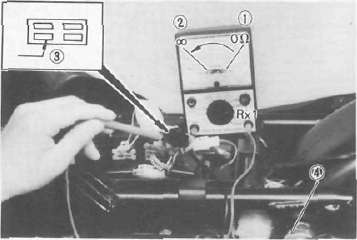
1. Disengaged 2. Engaged 3. Black/Yellow 4. Ground
- Printer-friendly version
- Log in to post comments