Inspection
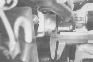
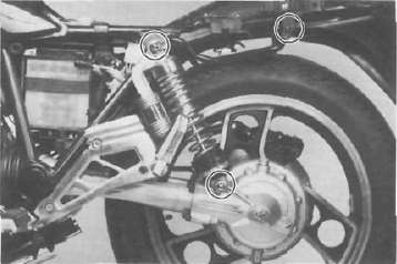
1. Remove the rear wheel and both shock absorbers. Grasp the swing arm and try to move it from side to side as shown. There should be no noticeable side play.

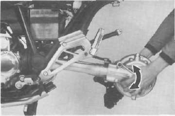
2. The swing arm is mounted on tapered bearings. Move the swing arm up and down as shown. The swing arm should move smoothly, without tightness, binding or rough spots that could indicate damaged bearings.
Adjustment
1. Measure the gap between the frame and the swing arm on the left and right sides. There should be not more than 1.6 mm (0.062 in) difference between the left and right gaps.
NOTE: It may be easier to inspect the gap with the rear wheel removed; however, such removal is not necessary.
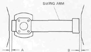
LESS THAN 1.6 mm (0.062 in) DIFFERENCE BETWEEN A AND B GAPS.
2. If the left and right gaps differ by more than the limit [1.6 mm (0.062 in)] adjust as follows:
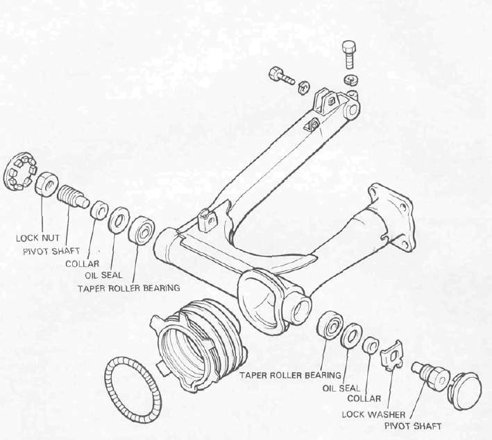
a. Remove the pivot shaft caps from the left and right sides of the swing arm.
b. Loosen both the left and right pivot shafts lock nuts.
c. Loosen the pivot shaft on the side of the greater swing arm/frame gap. Loosen only slightly (counterclockwise, approximately one-half turn). After loosening, tighten the opposite pivot shaft (clockwise) to 5 — 6 Nm (0.5 ~~ 0.6 m-kg, 3.6 - 4.3 ft lb).
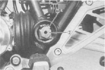
1. Lock nut 2 Pivot shaft
d. Measure the gap again between the frame and the swing arm. If the left and right gaps are not within 1.6 mm (0.062 in) of each other, repeat step. c.
e. When the left and right gaps are adjusted properly, tighten the pivot shaft lock nut.
NOTE: Do not allow the pivot shaft to turn while tightening the lock nut
Pivot shaft lock nut torque: 100 Nm (10 mkg, 72 ft lb).
Removal
1. Remove the middle gear flange holding bolts.
2. Remove the rear wheel and shock absorbers. Remove the rear brake assembly.
3. Remove the final gear assembly.
4. Remove the swing arm pivot caps, the pivot shafts and the swing arm.
Inspection and lubrication
1. Remove the oil seals and the bearings. Inspect the bearings for pitting or other damage. Make sure that the bearings roll freely. If a bearing is damaged, both bearings and both sets of inner and outer bearing races should be replaced.
CAUTION: Do not use compressed air to spin the bearings dry. This causes damage to the bearing surfaces.
NOTE: When installing new bearings, grease liberally with lithium base, waterproof wheel bearing grease.
2. Always replace the grease seals when bearings are removed.
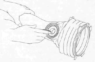
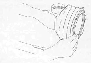
3. Examine the rubber boot for damage. Replace if damaged.
Installation
Installation of the swing arm can be accomplished by reversing the removal procedure. Observe adjustment procedures for obtaining equal frame/swing arm spacing.
CAUTION: A lock washer for left side pivot bolt must be replaced with a new one and the tab should be bent over along the bolt flat after tightening.
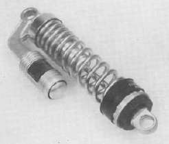
REAR SHOCK ABSORBER ("DE CARBON" SYSTEM) Handling notes
WARNING: This shock absorbers are provided with a separate type tank filled with high-pressure nitrogen gas. To prevent the danger of explosion, read and understand the following information before handling the shock absorbers.
The manufacturer can not be held responsible for property damage or personal injury that may result from improper handling.
1. Never tamper or attempt to disassemble the cylinder or the tank.
2. Never throw the shock absorber into an open flame or other hight heat. The shock absorber may explode as a result of nitrogen gas expansion and/ or damage to the unit.
3. Be careful not to damage any part of the gas tank. A damaged gas tank will impair the damping performance or cause a malfunction.
4. Take care not to scratch the contact surface of the pistion rod with the cylinder; or oil could leak out.
5. When scrapping the shock absorber, follow the instructions on disposal.
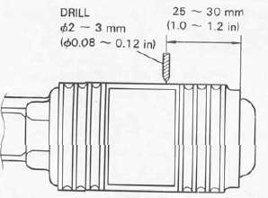
Notes on disposal
Before disposing the shock absorber, be sure to extract the nitogen gas. To do so, drill a 2 — 3 mm (0.08 ~ 0.12 in) hole through the tank at a position 25 ~~ 30 mm (1.0 — 1.2 in) from the bottom end of the tank. At this time, wear eye protection to prevent eye damage from escaping gas and/or metal chips.
Removal and reinstallation
1. Remove the seat and side covers (Left and right).
2. Remove the rear stay and rear fairing.
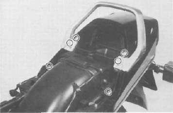
3. Remove the muffler securing bolts and remove the mufflers.
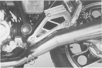
4. Remove the rear shock absorber mounting nuts and standing handle securing bolt. Then, pull out the rear shock absorber from the frame.
5. For reinstallation, reverse the procedure for removal. When installing, observe the specified tightening torque.
Upper (Left and right sides): 30 Nm (3.0 nrvkg. 22 ft-lb)
Bottom (Left and right sides): 30 Nm (3.0 mkg. 22 ft-lb)
Rear stay: 23 Nm (2.3 mkg. 17 ft lb)
Inspection
1. Check the rod. If it is bent or damaged, replace the shock absorber.
2. Check for oil leakage. If oil leakage is evident replace the shock absorber.
3. Operate shock absorber rod to check damping. There should be not noticeable damping as the shock extends.
- Printer-friendly version
- Log in to post comments