Middle gear
1. Damper disassembly
NOTE: Disassembly of the middle gear damper requires the damper compressor (special tool) and a hydraulic press.
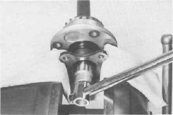
a. Place the middle drive shaft in a press with the damper compressor (special tool) in place as shown.
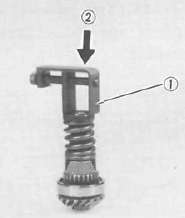
1. Damper compressor 2. Press
b. Press the damper spring and remove the spring retainers.
c. Remove the spring seat, spring, and damper cams from the drive shaft.
2. Inspection
a. Inspect the damper cam surfaces. Check for smooth cam action and excessive wear on the cam surface. If cam surface is severely worn, replace damper assembly.
b. Inspect the damper spring for fatigue, wear and damage. Replace as necessary.
c. Check bearing movement for damage to balls, rough spots, bearing looseness. Inspect gear teeth. If any gear tooth and/ or bearing are damaged, the gear set and/or bearing must be replaced.
3. Middle drive/driven shaft bearing removal
CAUTION: The following procedures should be performed only if the bearing or gear is to be replaced.
a. Middle drive gear
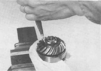
1) Bend down the lock washer of the nut with a suitable center punch.
2) Support the middle drive shaft in a vise securely.
Remove the drive pinion holding nut. Then, remove the drive pinion and bearing.
b. Middle driven gear
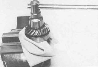
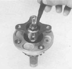
1) Support the drive flange in a vise securely. Remove the flange holding nut.
CAUTION: This holding nut has been locked with a thread locking compound, when reinstalling do not forget to apply a thread locking compound such as "LOCTITE" and punch.
2) Remove the drive flange from the driven shaft.
NOTE: Driven gear shaft bearing should be replaced together with a bearing housing.
Middle gear reassembly
a. Middle drive gear bearing and damper
1) Install the bearing onto the drive pinion and secure it with a new lock nut.
Tightening torque:
110 Nm (11.0 rrvkg, 80 ft lb)
2) Stake the lock washer of the nut to the slot on the drive pinion.
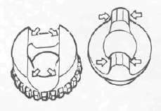
3) Install the driven damper cam onto the drive pinion shaft with the cam lobes positioned 90° from the row of shaft oil holes. Positioning tolerance is ± 1 spline (15°) from the 90° position.
4) Install the drive damper cams, spring, spring seat, and retainers using a press and the damper compressor.
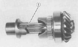
1. Oil hole
b. Middle driven gear
1) Install the new bearing housing assembly onto the driven pinion shaft
CAUTION: Do not press the bearing outer race. Always press the inner race with care when installing.
2) Install the drive flange and new "0-ring" onto the driven gear shaft. Apply a thread locking compound such as "LOCTITE" tothe shaft threads and tighten the nut to the specified torque.
Tightening torque:
110Nm (11.0 m-kg, 80 ft lb)
3) Stake the nut with a center punch to lock as shown.
4) Install the new "O-ring" onto the bearing housing.
- Printer-friendly version
- Log in to post comments