Piston and piston rings
1. Piston
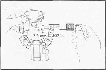
a. Measure the outside diameter of the piston at the piston skirt. Measurement should be made at a point 7.8 mm (0.307 in) above the bottom edge of the piston. Place the micrometer at right angles to the piston pin.
|
Size |
|
|
Oversize 1 |
- |
|
Oversize 2 |
67.50 mm (2.657 in) |
|
Oversize 3 |
- |
|
Oversize 4 |
68.00 mm (2.677 in) |
b. Determine piston clearance as follows: Minimum bore measurement
- Maximum piston measurement = Piston clearance
EXAMPLE:
67.00 mm (2.6378 in)
- 66.96 mm (2.6362 in) = 0.04 mm (0.0016 in)
Piston clearance
Piston clearance:
Standard: 0.030 — 0.050 mm
(0.0012 —0.0020 in) Service limit: 0.1 mm (0.0039 in)
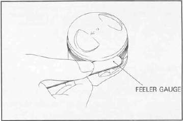
c. Piston ring/ring groove fit must have correct clearance. If the piston and ring have already been used, the ring must be removed and the ring groove cleaned of carbon. The ring should be then reinstalled. Use a feeler gauge to measure the gap between the ring and the land.
|
Side clearance |
Top |
0.03 — 0.07 mm (0.0012 -0.0028 in) |
|
2nd |
0.02 — 0.06 mm (0.0008 -0.0024 in) |
2. Piston ring a. The oversize top and middle ring sizes are stamped on top of the ring.
|
Oversize 1 |
- |
|
Oversize 2 |
0.50 mm (0.0197 in) |
|
Oversize 3 |
- |
|
Oversize 4 |
1.00 mm (0.0394 in) |
b. The expander spacer of the bottom ring (oil control ring) is color-coded to identify sizes.
The color mark is painted on the expander spacer.
Run-out limit: 0.03 mm (0.0012 in)
|
Size |
Color |
|
Oversize 1 |
- |
|
Oversize 2 |
Blue |
|
Oversize 3 |
- |
|
Oversize 4 |
Yellow |
c. Insert a ring into the cylinder, and push it approximately 20 mm (0.8 in) into the cylinder. Push the ring with the piston crown so the ring will be at a right angle to the cylinder bore. Measure the ring end gap with a feeler gauge. If the end gap exceeds tolerance, replace the whole set of rings.
NOTE: The end gap on the expander spacer of the oil control ring is unmeasurable. If the oil control ring rails show excessive gap, all three components should be replaced.
|
Standard |
Limit |
|
|
Top/2nd ring |
0.15 — 0.35 mm (0.0059 -0.0138 in) |
1.0 mm (0.039 in) |
|
Oil control (Rails) |
0.3 — 0.9 mm (0.012 —0.035 in) |
1.5 mm (0.059 in) |
Piston pin
1. Apply a light film of oil to pin. Install in connecting rod small end. Check for play. There should be no noticeable vertical play. If play exists, check connecting rod small end for wear. Replace pin and connecting rod as required.
2. The piston pin should have no noticeable free play in piston. If the piston pin is loose, replace the pin and/or the piston.
Crankshaft
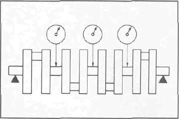
1. Crankshaft run-out
Support the crankshaft at both ends on V-blocks. Measure the amount of crankshaft run-out on the main bearing journals with a dial gauge while rotating crankshaft.
If run-out exceeds limit, replace crankshaft.
2. Inspection of bearings
Check the bearings. If the inner or outer surface is burned, flaked, rough, scratched or worn, the bearings should be replaced.
3. Measuring main bearing oil clearance
a. Clean all crankshaft and crankcase journal surfaces.
b. Place upper crankcase half upside-down on a bench. Install bearing inserts into top crankcase.
c. Install crankshaft into upper crankcase.
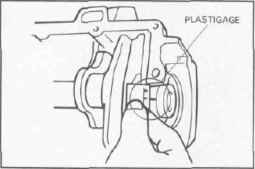
d. Place Plastigage on crankshaft journal surface to be inspected.
NOTE: Do not move crankshaft until clearance check has been completed.
e. Install bearings into bottom crankcase. Carefully, place lower crankcase onto upper crankcase.
f. Install crankcase holding bolts 1 through 10. Tighten to full torque in torque sequence cast on crankcase.
Crankcase torque (8 mm bolt): 24 Nm (2.4 mkg, 17 ft-lb)
g. Remove bolts in reverse assembly order (10, 9, 8 ... etc.)
h. Carefully remove lower crankcase. Measure width of Plastigage on crankshaft journals to determine clearance.
Main bearing oil clearance: 0.040 — 0.064 mm (0.0016 -0.0025 in)
4. Crankshaft main bearing selection a. Numbers used to indicate crankshaft journal sizes are stamped on the L.H. crank web. The first five (5) are main bearing journal numbers, starting with the left journal. The four (4) rod bearing journal numbers follow in the same sequence.
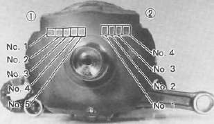
The upper crankcase half is numbered 4, 5, or 6 as shown.
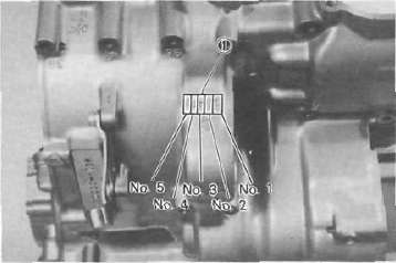
1. Main bearing numbers
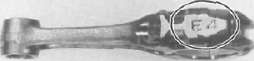
b. The connecting rods are numbered 4 or 5. The numbers for rods are stamped with ink on the rod itself.
c. The proper bearing selection is made by subtracting the crankshaft journal number from the crankcase or rod size number. Use the color code to choose the proper bearing. EXAMPLE:
Rod No. (Minus) Journal No. = Bearing No.
5-2 = 3 No. 3 bearing is Brown. Use Brown bearing inserts.
|
BEARING COLOR CODE |
|
|
No. 1 |
Blue |
|
No. 2 |
Black |
|
No. 3 |
Brown |
|
No. 4 |
Green |
|
'No. 5 |
Yellow |
" For crankshaft main bearing only.
d. When assembling, apply a liberal coat of motor oil to all bearing surfaces.
NOTE: When applying final torque to the rod caps, observe the following procedures.
e. Apply molybdenum disulfide grease to connecting rod bolt threads. Apply tor-que evenly to both ends of the cap. While tightening, if a torque of 38 Nm (3.8 m kg, 27 ft-lb) or more is reached, DO NOT STOP tightening until final torque is reached. If tightening is interrupted between 35 Nm (3.5 mkg, 25ft-lb) and 41 Nm (4.1 nrvkg. 30 ft-lb), loosen the nut to less than 30 Nm (3.0 nrvkg, 22 ft-lb) and start again. Tighten to full torque specification without pausing.
Rod bearing oil clearance: 0.016 — 0.040 mm (0.0006 —0.0016 in)
- Printer-friendly version
- Log in to post comments