INSPECTION
Brake Shoe
1. Measure brake shoes friction material thickness (1) with calipers. Replace if below limit.
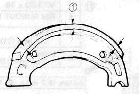
Brake Shoe Thickness 4 mm (0.16 in)
Replacement Limit: 2 mm (0.08 in)
2. Inspect: Brake shoes. Sand glazed parts with coarse sandpaper.
Brake Drum
1. Inspect the brake drum Inner surface. Wipe off any oil with rag soaked in lacquer thinner or solvent. Polish brake drum lightly and evenly with emery cloth to remove scratches if necessary.
Brake Shoe Plate
1. Remove camshaft and inspect cam face. Replace if worn. Grease camshaft with high temperature brake grease..
NOTE:
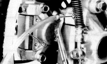
Place alignment marks (1) on the cam lever and camshaft when disassembling.
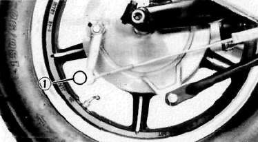
2. Adjust rear brake free play. Turn adjuster (1) as needed.
|
Adjuster |
Rear Brake Free Play |
|
Turn clockwise |
to reduce |
|
Turn counterclockwise |
to increase |
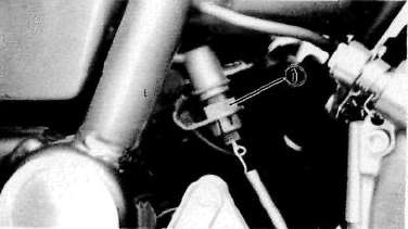
3. Adjust: rear brake light switch (1)
FRONT BRAKE
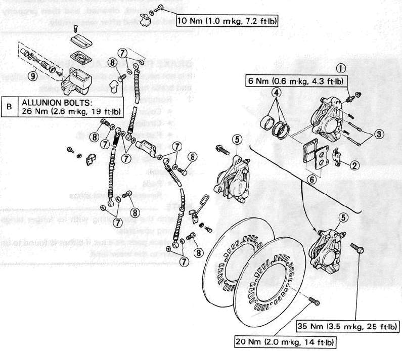
(1) Bleed screw
(2) Pad spring
(3) Pad retaining pin
(4) Caliper piston assembly (Replace as a set)
(5) Caliper
(6) Brake pads (Replace as a set)
(7) Copper washer
(8) Union bolt
(9) Master cylinder kit (Replace as a set)
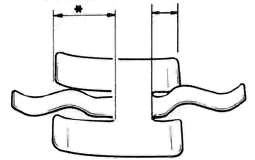
PAD SPRING
'Install the pad spring with its longer tangs facing upwards.
|
c |
PAD THICKNESS: Std.: 5.5 mm (0.217 in) |
|
D |
WEAR LIMIT: 0.5 mm (0.0197 in) |
CAUTION:
Disc brake components rarely require disassembly. Do not:
• Disassembe components unless absolutely necessary.
• Use solvents on internal brake component.
• Use contaminated brake fluid for cleaning. Use only clean brake fluid.
• Allow brake fluid to come in contact with the eyes otherwise eye injury may occur.
• Allow brake fluid to contact painted surfaces or plastic parts otherwise damage may occur.
• Disconnect any hydraulic connection otherwise the entire system must be disassembled, drained, cleaned, and then properly filled and bled after reassembly.
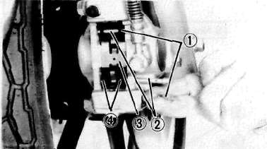
BRAKE PAD REPLACEMENT
It is not necessary to disassemble brake caliper and brake hose to replace brake pads.
1. Remove:
• Cover
• Circlips (1)
• Pad retaining pins (2)
• Pad spring (3)
• Pads (4)
2. Install Pads by reversing removal steps.
NOTE:
• Install the pad spring with its longer tangs facing upwards.
• Replace pads as a set if either is found to be worn to the wear limit.
CALIPER DISASSEMBLY
1. Remove:
• Brake hose (1)
• Caliper securing bolts (2)
• Brake pads
2. Remove:
• Caliper piston assembly
Use compressed air and proceed carefully.
Caliper piston removal steps:
• Using a rag, lock the right side piston.
• Blow compressed air into the hose joint opening to force out the left side piston from the caliper body.
• Remove the dust and piston seals and reinstall the piston.
• Repeat previous step to force out the right side piston from the caliper body.
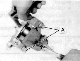
DO NOT LOOSEN bolts [A]
• Cover piston with rag and use extreme caution when expelling piston from cylinder.
• Never attempt to pry out piston.
MASTER CYLINDER DISASSEMBLY
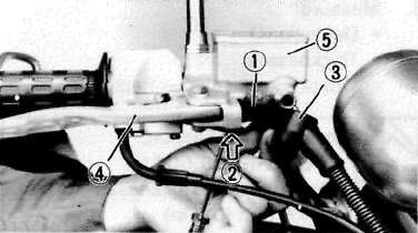
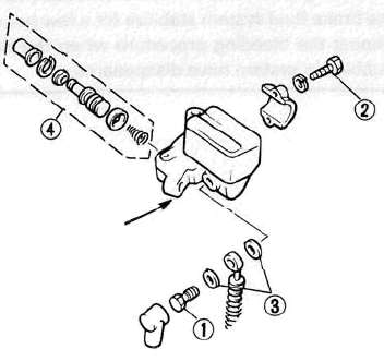
1. Remove brake light switch (1). Push (2) the brake light switch stopper.
Remove brake hose (3), brake lever (4) and spring then master cylinder assembly (5)
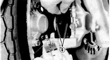
2. Remove cap (1). Drain remaining fluid. Remove master cylinder dust boot (2), circlip (3) and master cylinder cup assembly.
NOTE:
Be sure to reinstall the larger diameter lips of the cylinder cups first.
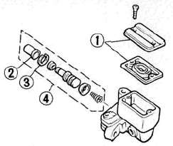
(4) Master cylinder kit
INSPECTION AND REPAIR
|
Recommended Brake Component Replacement Schedule |
|
|
Brake pads |
As required |
|
Piston seal, dust seal |
Every 2 years |
|
Brake hoses |
Every 4 years |
|
Brake fluid |
Replace only when brakes disassembled |
1. Inspect caliper piston assembly for scratches. Replace.if damaged. Inspect brake pad. Replace as a set if under wear limit (1).
Brake Pad Wear Limit: 0.5 mm (0.0197 in)
(2) Wear indicator
2. Inspect master cylinder body for scratches — Replace if damaged.
Clean all passages with new brake fluid.
Inspect all Brake hoses for Cracks/Frayed/Damage/Over four years old — Replace as necessary.
3. Measure rotors for deflection (1) and thickness (2). Replace if out of specification.
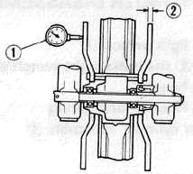
Maximum Deflection: 0.15 mm (0.006 in)
Minimum Disc Thickness: 4.5 mm (0.2 in)
ASSEMBLY
Caliper
NOTE:
• All internal parts should be cleaned in new brake fluid only.
• Internal parts should be lubricated with brake fluid when installed.
• Replace the piston and dust seals whenever the caliper is disassembled.
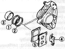
1. Install piston seal (1), dust seal (2), piston (3), pad spring (4), brake pads (5) into caliper assembly. Assemble caliper assembly to forks.
2. Tighten caliper securing bolts (1). Torque to 35 Nm(3.5 m-kg, 25 ft lb)
• Brake hose union bolt (2). Torque to 26 Nm (2.6 m-kg, 19 ft-lb)
3. Bleed the air completely (see below)
Master Cylinder
1. Install master cylinder kit into master cylinder. Assemble master cylinder to handlebar and brake line to master cylinder. Torque Union Bolt (1) to 26 Nm (2.6 m-kg, 19 ft-lb).
Torque Master Cylinder Holding Bolt (2) to 10 Nm (1.0 m-kg, 7.2 ft-lb)
2. Bleed the air completely.
(3) Copper washer (4) Master cylinder kit
AIR BLEEDING
Bleed the brake system if:
• The system has been disassembled.
• A brake hose has been loosened or removed.
• The brake fluid is very low.
• The brake operation is faulty.
Warning:
A dangerous loss of braking performance may occur if the brake system is not properly bled.
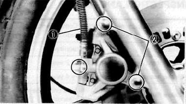
Air bleeding steps:
a. Add proper brake fluid to the reservoir.
b. Install diaphragm. Be careful not to spill any fluid or allow the reservoir to overflow.
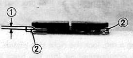
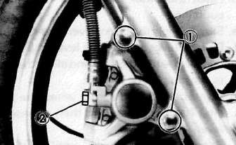
c. Connect the clear plastic tube (1) (4.5 mm, 3/16 in inside dia.) tightly to the caliper bleed screw (2).
d. Place the other end of the tube into a container.
e. Slowly apply the brake lever several times.
f. Pull the lever in. Hold the lever in position.
g. Loosen the bleed screw and allow the lever to travel towards its limit.
h. Tighten the bleed screw when the lever limit has been reached; then release the lever.
i. Repeat steps e to huntil of the air bubbles have been removed from the system.
NOTE:
It can be difficult to force air bubbles downwards to the bleeder. It may be necessary to secure the brake lever to the handlebar in the fully operated position and allow it to sit for a few hours or overnight so bubbles can stabilize, rise up and escape into the reservoir.
Alternatively: connect clear plastic tube (1) to vacuum bleeder and draw fluid down by vacuum.
Take care not to allow reservoir to empty during the bleeding process.
- Printer-friendly version
- Log in to post comments