ELECTRIC STARTING SYSTEM
CIRCUIT DIAGRAM
Below circuit diagram shows starter circuit in wiring diagram.
.
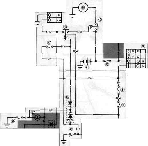
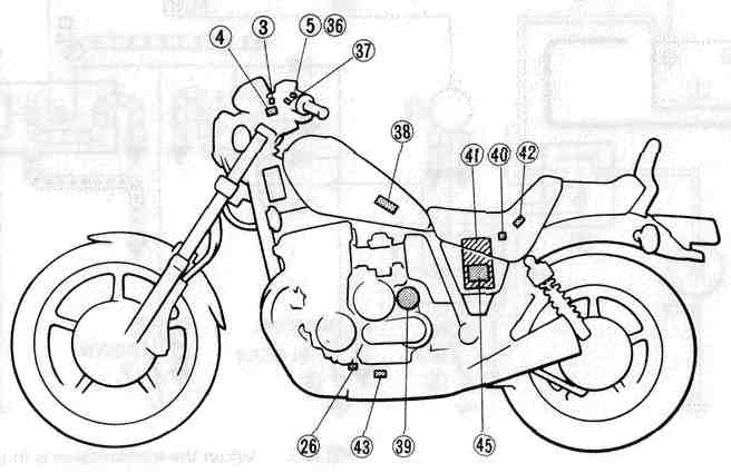
3 Main switch
4 Fuse "IGNITION" (10A)
5 Engine stop switch
26 Neutral switch
36 Starter switch
37 Clutch switch
38 Starting circuit cut-off relay (Relay assembly)
39 Starter motor
40 Starter relay
41 Battery
42 Fuse "MAIN" (30A)
43 Sidestand switch 45 Diode
COLOR CODE
|
0 |
Orange |
Lg |
Light green |
B/Y |
Black/Yellow |
|
R |
Red |
Y/G |
Yellow/Green |
L/W |
Blue/White |
|
L |
Blue |
Y/R |
Yellow/Red |
L/G |
Blue/Green |
|
Br |
Brown |
Y/B |
Yellow/Black |
L/R |
Blue/Red |
|
B |
Black |
Y/L |
Yellow/Blue |
L/B |
Blue/Black |
|
Y |
Yellow |
Br/W |
Brown/White |
G/L |
Green/Blue |
|
W |
White |
R/B |
Red/Black |
G/R |
Green/Red |
|
G |
Green |
R/L |
Red/Blue |
G/Y |
Green/Yellow |
|
P |
Pink |
R/W |
Red/White |
G/W |
Green/White |
|
Dg |
Dark green |
R/Y |
Red/Yellow |
W/R |
White/Red |
|
Ch |
Chocolate |
B/R |
Black/Red |
W/B |
White/Black |
|
Gy |
Gray |
B/W |
Black/White |
W/G |
White/Green |
|
Sb |
Sky blue |
|
|
|
|
ELECTRIC STARTING SYSTEM
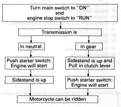
STARTING CIRCUIT OPERATION
The starting circuit on this model consists of the starter motor, starter relay, starter safety unit, and sidestand relay. If the engine stop switch and the main switch are both on, the starter motor can operate only if:
• The transmission is in neutral (the neutral switch is on.)
• The sidestand is up (the sidestand switch is on) and the clutch lever is pulled in (clutch switch is on).
Battery Starter motor Starter relay Starter safety unit (Relay assembly) Starter switch Neutral switch
Sidestand switch Clutch switch Sidestand relay Tachometer Main switch Engine stop switch To ignitor switch
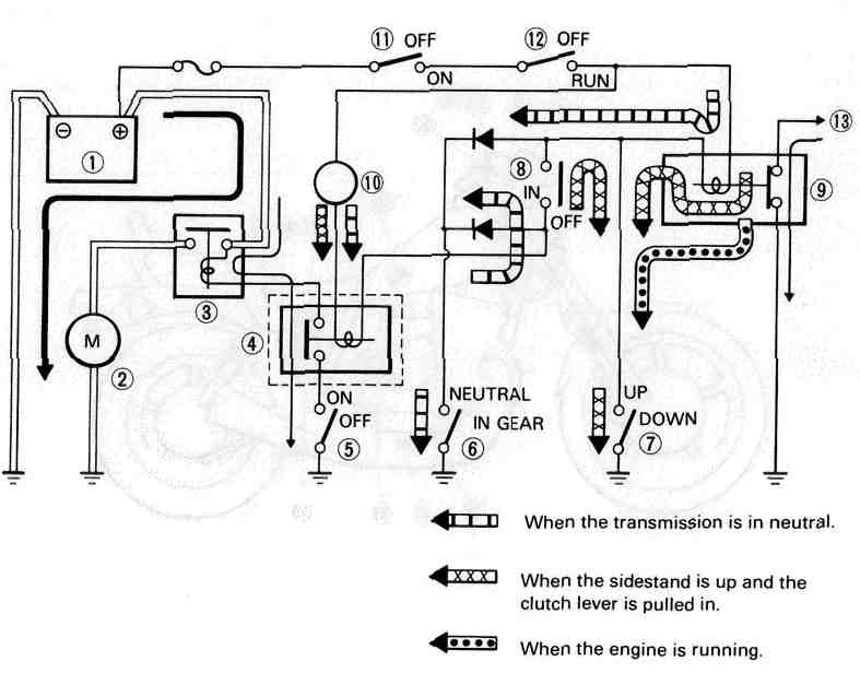
1 Battery 2 Starter motor 3 Starter relay 4 Starting circuit cut-off relay
5 Starter switch 6 Neutral switch 7 Sidestand switch 8 Clutch switch
9 Sidestand relay 10 Tachometer 11 Main switch 12 Engine stop switch
13 To ignitor unit
|
Turn main switch to "ON" and engine stop switch to "RUN" |
|
|
Transmission is |
|
|
▼ |
▼ |
|
In neutral |
In gear |
|
▼ |
▼ |
|
Push starter switch Engine will start |
Raise Sidestand and Pull in clutch lever |
|
▼ |
▼ |
|
Ensure Sidestand is up |
Push starter switch: Engine will start |
|
▼ |
▼ |
|
Motorcycle can be ridden |
|
TROUBLESHOOTING CHART
|
THE STARTER MOTOR DOES NOT OPERATE. |
|
|
|
▼ |
|
|
|
|
||
|
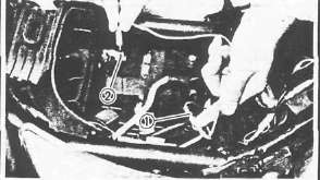
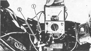
Connect "L/W" lead from the starter relay 1 to the battery negative (-) terminal 2 ; use a jumper lead. |
► |
The engine does not rev smoothly. |
|
▼ |
||
|
Recharge or replace the battery. |
||
|
|
||
|
► |
The engine does not operate. | |
|
▼ |
||
|
▼ |
|
|
|
Check the battery voltage (12V) on the "L/W" lead from the starter relay. |
||
|
The engine operates. |
||
|
▼ |
||
|
▼ |
||
|
Main and engine stop switches are turned to "ON". |
||
|
If the starter relay does not click, check the starter relay and starter motor. |
||
| ▼ | ||
|
|
||
|
|
||
|
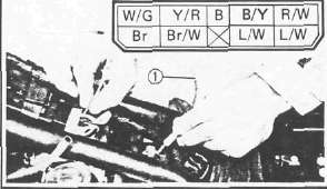
Connect "B/Y" lead to "ground" on the frame; use a jumper lead 1. |
||
|
► |
|
|
|
If the relay unit does not click, check the battery voltage (12V) on the "R/W" lead. |
||
|
|
▼ |
|
|
Check for an open or poor connection between the main switch and relay unit. |
||
|
▼ |
||
|
If the relay unit clicks, check the starter, sidestand, clutch and neutral switches. Replace switch(es) if necessary. |
|
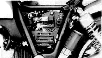
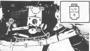
STARTER SAFETY UNIT (Relay Assembly)
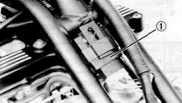
1. Remove:
• Seat
• Fuel tank
• Relay assembly ®
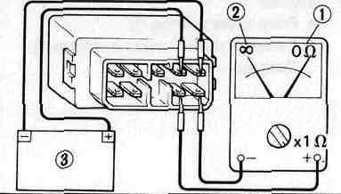
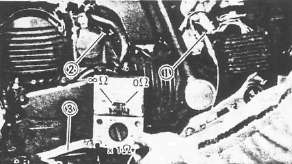
2. Check:
• Relay contacts Use 12V battery (§) and Pocket Tester (YU-03112). Out of specification — Replace relay.
Battery Connected: OH ® Battery disconnected: °° ©
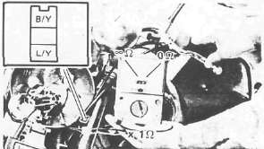
DIODE
1. Remove:
• Left side cover
• Diode ®
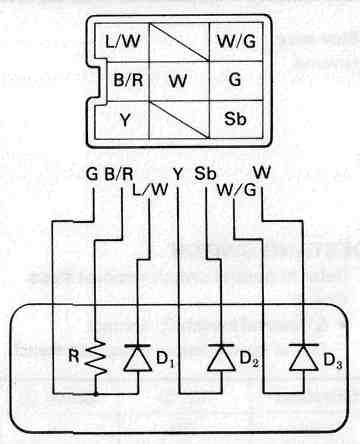
2. Check:
• Diode continuity/discontinuity
Defective element(s) — Replace the unit.
|
Checking element |
Pocket tester connecting point |
Good |
|
|
(+) (red) |
(-) (black) |
||
|
D, |
G |
L/W |
O |
|
L/W |
G |
X |
|
|
D2 |
Y |
Sb |
o |
|
Sb |
Y |
X |
|
|
D3 |
W/G |
W |
o |
|
W |
W/G |
X |
|
|
R |
G |
B/R |
8.20 |
O: Continuity (OH) (Scale H x 1000) X : Discontinuity («>) (Scale ohm x 1)
NOTE:
The results "O" or "X" should be reversed according to the pocket tester polarity.
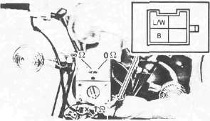
NEUTRAL SWITCH
1. Remove:
• Left side cover
• Panel
2. Check the neutral switch contact. Replace if out of specification.
|
Shift pedal 3 |
In neutral |
In gear |
|
Tester |
0Ω |
∞Ω |
1 Blue lead
2 Ground
SIDESTAND SWITCH
1. Refer to neutral switch removal steps.
2. Check the sidestand switch 1 contact. Replace switch if out of specification.
|
Sidestand |
Up 2 |
Down 3 |
|
Tester |
0Ω |
∞Ω |
CLUTCH SWITCH
1. Remove headlight unit
2. Check clutch switch contact. replace if out of specification.
|
Clutch lever |
Pull in |
Not pull in |
|
Tester |
0Ω |
∞Ω |
STARTER SWITCH
1. Remove the headlight unit.
2. Check starter switch contact. Replace if out of specification.
|
Starter switch |
ON |
OFF |
|
Tester |
0Ω |
∞Ω |
STARTER RELAY Inspection
Preparation steps:
• Disconnect starter motor red lead.
• Connect Pocket Tester leads to relay terminals.
•Turn main switch to "ON".
• Turn engine stop switch to "RUN".
• Move shift pedal to "NEUTRAL"
|
Push starter switch to "ON" |
||
|
▼ |
▼ |
|
|
Relay clicks and tester reads 0Ω |
Relay does not click and tester does not read 0 Ω |
|
|
▼ |
▼ |
|
|
OK |
Measure resistance: |
|
|
|
||
|
▼ |
▼ | |
|
Resistance less than 1 Ω |
Resistance more than 1 Ω | |
|
▼ |
▼ | |
|
Check connections |
Replace relay | |
- Printer-friendly version
- Log in to post comments