CHASSIS
A. Fuel petcock
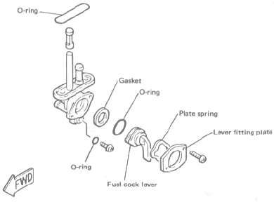
If the fuel petcock is leaking or excessively contaminated, it should be removed from the fuel tank and inspected.
1. Remove the fuel tank, and position it so that fuel wilt not spill when the petcock is removed.
2. Remove the petcock and inspect the filter screen. Replace the filter if srious-ly contaminated.
3. Remove the screws on the front and rear of the petcock and remove the plate, gaskets, lever, and diaphragm.
4. Inspect all components and replace any that are damaged. If the diaphragm is in any way damaged, or the petcock body gasket surfaces scratched or corroded, the petcock assembly must be replaced. If there is abrasive damage to any component, the fuel tank must be drained and flushed.
5. Reassemble the petcock and install it on the fuel tank.
B. Front and rear brake
1. Brake adjustment
a. Front brake lever free play adjustment. The brake can be adjusted by simply adjusting the free play of the brake lever. The piston in the caliper moves forward as the brake pad wears out, automatically adjusting the clearance between the brake pads and brake disc.
CAUTION:
Proper lever free play is essential to avoid excessive brake drag.
1. Adjuster 2. Lock nut a. 5 - 8 mm (0.2 - 0.3 in)
1) Loosen the adjuster locknut on the brake lever.
2) Turn the adjuster so that the brake lever movement at the lever end is 5- 8 mm (0.2-0.3 in) before the adjuster contacts the master cylinder piston.
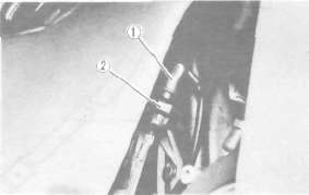
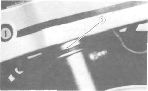
3) After adjusting, tighten the locknut. b. Rear brake pedal height adjustment
1) Loosen the adjuster locknut {for pedal height).
2) By turning the adjuster bolt clockwise or counterclockwise, adjust the brake pedal position so that its top end is approximately 20 mm {0.78 in) below the footrest top end.
3) Secure the adjuster locknut.
WARNING:
After adjusting the pedal height, the brake pedal free play should be adjusted.
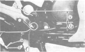
1. Adjuster bolt (for pedal height) 2. Locknut 3. Footrest
4. Pedal height 40 mm (1.6 In) 5. Free play 20 30 mm (0.8 - 1.2 in)
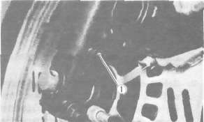
c. Rear brake pedal free play adjustment Turn the adjuster on the brake rod clockwise or counterclockwise to provide the brake pedal with a free play of 20~30 mm {0.8-1.2 in).
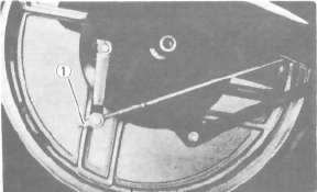
1. Adjuster
WARNING:
Check the operation of the brake light after adjusting the rear brake.
2. Front brake pad and rear brake shoe check
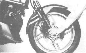
a. Front brake pad
To check, look at the pad in front. If any pad is worn to the wear limit, replace both pads in the caliper.
1. Wear indicator
b. Rear brake shoe
To check, see the wear indicator position while depressing the brake pedal. If the indicator reaches to the wear limit line, replace the shoes.
1. Wear limit 2. Wear indicator
3. Brake fluid
Insufficient brake fluid may allow air to enter the brake system, possibly causing the brake to become ineffective. Check the brake fluid level and replenish when necessary, observing these precautions:
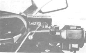
1. Lower level
a. Use only the designated quality brake fluid; otherwise, the rubber seals may deteriorate, causing leakage and poor brake performance.
Recommended brake fluid: DOT# 3
b. Refill with the same type and brand of brake fluid; mixing fluids may result in a harmful chemical reaction and lead to poor performance.
c. Be careful that water or other contamination does not enter the master cylinder when refilling. Water will significantly lower the boiling point and may result in vapor lock.
d. Brake fluid may erode painted surfaces or plastic parts. Always clean up spilled fluid immediately.
e. Check the cause if the brake fluid level goes down.
Brake fluid replacement
1. Complete fluid replacement should be done only by trained Yamaha service personnel or other qualified mechanic.
2. Complete fluid replacement should be done whenever the caliper cylinder or master cylinder is disassembled, or the fluid becomes seriously contaminated.
3. Replace the following components whenever damaged or leaking, also:
a. Replace all brake seals every two years.
b. Replace all brake hoses every four years.
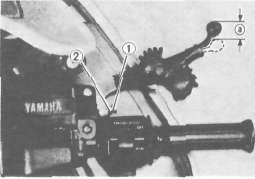
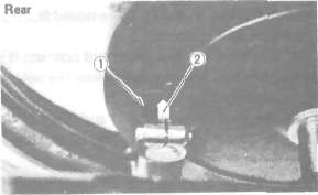
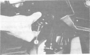
Brake light switch adjustment
The brake light switch is operated by the movement of the brake pedal. To adjust, hold the switch body with the hand so it does not rotate and turn the adjusting nut. Proper adjustment is achieved when the brake light comes on slightly before the brake begins to take effect.
1. Switch body 2. Adjusting nut
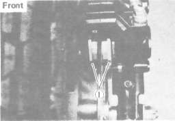
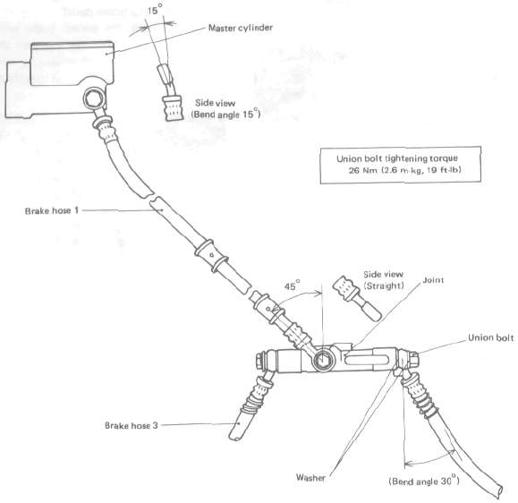
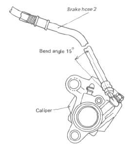
Front brake hose installation
The front brake hoses should be installed as shown in the illustration.
NOTE:
1. When installing the brake hose to the master cylinder, the joint, or the caliper, pay attention to the banjo fitting angle; see the illustration.
2. When installing the banjo fitting to the caliper or the joint, use the stopper.
3. When installing the banjo fitting to the master cylinder, brake hose 1 should not have any excessive twists or bends in it, nor should it be tightly stretched.
FRONT BRAKE HOSE INSTALLATION
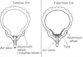
C. TubeIess tires and aluminum wheels
This motorcycle is equipped with aluminum wheels designed to be compatible with either tube or tubeless tires. Tubeless tires are installed as standard equipment.
WARNING:
Do not attempt to use tubeless tires on a wheel designed for use only with tube-type tires. Tire failure and personal injury may result from sudden deflation.
Tube-type Wheel -> Tube-type tires only
Tubeless type Wheel -> Tube-type or Tubeless tires
When using tube-type tires, be sure to install the proper tube also.
To insure maximum performance, long service, and safe operation, note the following precautions.
1. Check tire pressure before riding; adjust as necessary.
2. Before operation, always check the tire surfaces for wear and/or damage; look for cracks, glass, nails, metal fragments, stones, etc. Correct any such hazard before riding.
3. Always inspect the aluminum wheels before a ride. Place the motorcycle on its centerstand and check for cracks, bends, or warpage of the wheels. Do not attempt even small repairs to the wheel. If a wheel is deformed or cracked, it must be replaced.
4. Tires and wheels should be balanced whenever either one is changed or replaced. Failure to have a wheel assembly balanced can result in poor performance, adverse handling characteristics, and shortened tire life.
5. After installing a tire, ride conservatively to allow the tire to seat itself on the rim properly. Failure to allow proper seating may cause tire failure, resulting in damage to the motorcycle and injury to the rider.
6. After repairing or replacing a tire, check to be sure the valve stem locknut is securely fastened. If not, torque it as specified.
Tightening torque: 0.15 m-kg (1.1 ft-lb)
D. Front fork oil change
NOTE:
It is recommended that you proceed to the front fork oil change after clearing the front fork area of the fairing. This makes the work easier without the fairing being damaged.
WARNING:
1. Fork oil leakage cause loss of stability and safe handling. Oil can contaminate front brakes causing loss of braking power. Have any problem corrected before operating the motorcycle.
2. Securely support the motorcycle so there is no danger of it falling over.
1, Raise the motorcycle or remove the front wheel so that there is no weight on the front end of the motorcycle.
2. Remove the handlebar cover and handlebars.
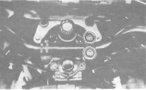
3. Remove the air valve cap from the left fork.
1, Air valve cap
4. Keep the valve open while pressing it for several seconds so that the air can be let out of the inner tube.
l.Push
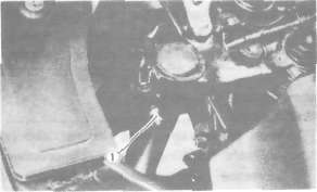
5. Remove the rubber cap from the top of each fork.
6. Loosen the pinch bolts and remove the cap bolt from each inner tube.
1. Cap bolt 2 Pinch bolt
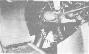
7. Place an open container under each drain hole. Remove the drain screw from each outer tube.
WARNING:
Do not allow oil to contact the disc brake components. If any oil should contact the brake components, it must be removed before the motorcycle is operated. Oil will cause diminished braking capacity and will damage the rubber components of the brake assembly.
1. Drain screw
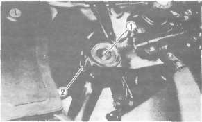
8. When most of the oil has drained, slowly raise and lower the outer tubes to pump out the remaining oil.
9. Inspect the drain screw gasket. Replace if damaged. Reinstall the drain screw.
10. Pour the specified amount of oil into the fork inner tube.
Front fork oil (each fork): 238 cm3 (8.4 Imp oz, 8.0 US oz) Yamaha Fork Oil 10wt or equivalent
11. After filling, slowly pump the outer tubes up and down to distribute the oil.
12. Inspect the 0-ring on the cap bolt.
13. Reinstall the cap bolt and the rubber cap. Then, tighten the pinch bolts.
Tightening torque:
Cap bolt: 20 Nm (2.0 m-kg, 14.0 ft-lb)
Pinch bolt: 17 Nm (1.7 m-kg, 12.0 ft-lb)
14. Fill the fork with air using a manual air pump or other pressurized air supply. Refer to "Front fork and rear shock absorber adjustment" for proper air pressure adjusting.
Maximum air pressure: 118 kPa (1.2 kg/cm2, 17 psi)
Do not exceed this amount.
15. Reinstall the air valve cap to the left fork.
16. Reinstall the handlebars and handlebar cover.
NOTE:
First tighten the bolts on the front side of the handlebar holder, and then tighten the bolts on the rear side.
Handlebar upper holder tightening torque: 19 Nm (1.9 m-kg, 13.0 ft-lb)
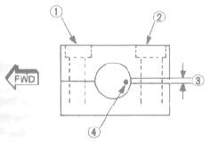
1.1st 2. 2nd 3. Gap 4. Punch mark
Front fork and rear shock adjustment
CAUTION:
Don't dent the air chamber nor damage the air hose. It will result in an air leakage.
Front fork:
NOTE:
Since the right and left front forks are connected by air hose, there is only one valve where the air pressure is measured and adjusted.
1. Air pressure
a. Elevate the front wheel by placing the motorcycle on the centerstand.
NOTE:
When checking and adjusting the air pressure, there should be no weight on the front end of the motorcycle.
b. Remove the air valve cap.
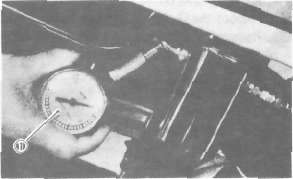
c. Using the air check gauge, check and adjusted the air pressure. If the air pressure is increased, the suspension becomes stiffer and if decreased, it becomes softer.
To increase: Use a manual air pump or other pressurized air supply.
To decrease: Release the air by pushing the valve pin.
1. Air check gauge
NOTE:
An optional air check gauge is available. P/No. 2X4-2811A-00
Standard air pressure: 39.2 kPa (0.4 kg/cm3, 5.7 psi)
Maximum air pressure: 118 kPa (1.2 kg/cm2, 17 psi)
Minimum air pressure: 39.2 kPa (0.4 kg/cm2, 5.7 psi)
CAUTION:
Never exceed the maximum pressure or oil seal damage may occur.
WARNING:
Never pressurize the front fork above the maximum or below the minimum air pressure. It will cause damage to front fork and/or loss Of motorcycle control.
d. Reinstall the air valve cap.
E. Rear shock absorber
NOTE:
Since the right and left shock absorbers are connected by air hose, there is only one valve where the air pressure is measured and adjusted.
1. Air pressure
a. Elevated the rear wheel by placing the motorcycle on the centerstand.
NOTE:
When checking and adjusting the air pressure, there should be no weight on the rear end of the motorcycle.
b. Remove the air valve cap.
c. Using the air check gauge, check and adjust the air pressure. If the air pressure is increased, the suspension becomes stiffer, and if decreased, it becomes softer,
To increase: Use a manual air pump or other pressurized air supply,
To decrease. Release the air by pushing the valve pin.
1. Air check gauge
NOTE: An optional air check gauge is available. P/No. 2X4-2811A-00
Standard air pressure: 98.1 kPa (1.0 kg/cm2, 14 psi)
Maximum air pressure: 392 kPa (4.0 kg/cm2, 57 psi)
Minimum air pressure: 98.1 kPa (1.0 kg/cm2, 14 psi)
CAUTION:
Never exceed the maximum pressure or oil seal damage may occur.
WARNING:
Never pressurize the shock absorber above the maximum or below the minimum air pressure. It will cause damage to rear shock absorber and/or loss of motorcycle control.
d. Reinstall the air valve cap.
2. Damping
a. Turning the damping adjuster to increase or decrease the damping.
b. If the damping adjuster is turned toward the "4", the damping becomes harder; if the adjuster is turned toward the "1", damping becomes softer.
Standard position - No. 1
No. 1 - Minimum damping
No. 4 — Maximum damping
1. Damping adjuster
Always the shock absorbers on each side to the same position. Uneven adjustment will cause an improper riding position.
F. Steering head adjustment
The steering assembly should be checked periodically for looseness.
1. Raise the front end of the motorcycle so that there is no weight on the front wheel.
2. Grasp the bottom of the forks and gently rock the fork assembly backward and forward, checking for looseness in the steering assembly bearings.
3. If there is looseness in the steering head, loosen the steering stem and front fork pinch bolts and steering fitting bolt.
4. Use a steering nut wrench to loosen top steering fitting nut. The top nut serves as a locknut.
5. Tighten the lower steering fitting nut until the steering head is tight, but does not bind when forks are turned.
6. Retighten the top steering fitting nut, steering fitting bolt and steering stem and front fork pinch bolts, in that order.
7. Recheck steering adjustment to make sure there is no binding when the forks are moved from lock to lock. If necessary, repeat adjustment procedure.
G. Cable inspection and lubrication
Warning:
Damage to the outer housing of the various cables may cause corrosion; free movement could be obstructed. An unsafe condition may result, so replace such cables as soon as possible.
1. If the inner cables do not operate smoothly, lubricate or replace them.
Recommended lubricant:
Yamaha Chain and Cable Lube or SAE 10W30 motor oil
H. Throttle cable and grip lubrication The throttle twist grip assembly should be greased when the cable is lubricated, since the grip must be removed to get at the end of the throttle cable. Two screws clamp the throttle housing to the handlebar. Once these two are removed, the end of the cable can be held high to pour in several drops of lubricant. With the throttle grip disassembled, coat the metal surface of the grip assembly with a suitable all-purpose grease to cut down friction.
I. Rear arm pivot bearings The swingarm must pivot freely on its bearings but not have any excess play. Check and adjust pivot bearings if necessary.
J. Brake and change pedals/brake and clutch levers Lubricate the pivoting parts of each lever and pedal.
Recommended lubricant:
Yamaha Chain and Cable Lube or SAE 10W30 motor oil
K. Centerstand and sidestand pivots Lubricate the centerstand and sidestand at their pivot points.
Recommended lubricants:
Yamaha Chain and Cable Lube or SAE 10W30 motor oil
- Printer-friendly version
- Log in to post comments