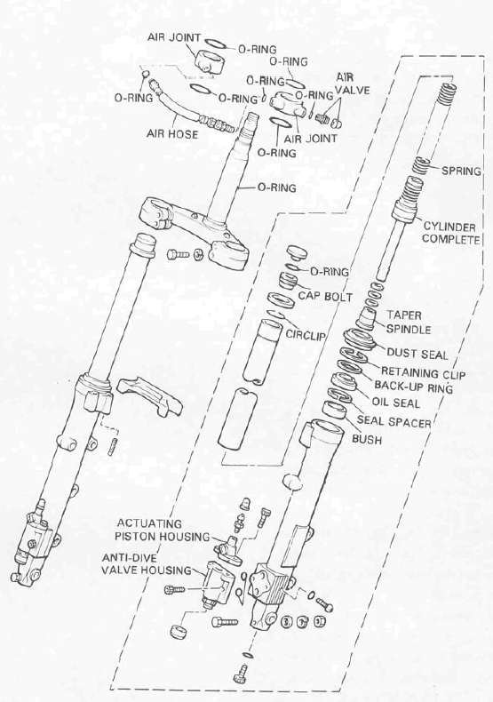
900RK

Anti-Dive system

Submitted by xjcdadmin on Sat, 06/22/2013 - 18:34

System inspection

1.      Apply the front brake for a few minutes and check to see if any brake fluid leaks out of the pipe joints, the master cylinder, or the actuating piston housing.

2.      Check the fork for fork oil leakage.

3.      Turn the anti-dive adjusting bolt to the maximum position.

Front Forks

Submitted by xjcdadmin on Sat, 06/22/2013 - 18:28

Removal and disassembly

WARNING: Securely support the motorcycle so it won't fall over when the front wheel and front forks are removed.

1.      Remove the front wheel. Refer to "FRONT WHEEL"

Tires

Submitted by xjcdadmin on Sat, 06/22/2013 - 17:38

To ensure maximum performance, long service, and safe operation, note the following: Tire air pressure

Always check and adjust the tire pressures before operating the motorcycle.

Brakes

Submitted by xjcdadmin on Sat, 06/22/2013 - 17:33

CAUTION: Disc brake components rarely require disassembly. Do not disassemble components unless absolutely necessary. If any hydraulic connection in the system is opened, the entire system should be disassembled, drained, cleaned and then properly filled and bled upon reassembly. Do not use solvents on brake internal components. Solvents will cause seals to swell and distort. Use only clean brake fluid for cleaning. Use care with brake fluid.

Rear Wheel

Submitted by xjcdadmin on Sat, 06/22/2013 - 17:26

Removal

1.      Place the motorcycle on the center stand.

2.      Remove the seat. Next, remove the rear fender installation bolts and remove the rear fender.

Front Wheel

Submitted by xjcdadmin on Sat, 06/22/2013 - 17:10

FRONT WHEEL

Removal

1.      Place the motorcycle on the center stand.

2.      Remove the speedometer cable from the speedometer.

3.      Remove the front fender securing bolts and remove the fender.

Middle Gear

Submitted by xjcdadmin on Sat, 06/22/2013 - 11:27

MIDDLE GEAR/DAMPER

a. Middle gear lash 0 2 mm (0.008 in)

d. Measure the gap between the driven gear bearing housing flange and the crankcase with a feeler gauge. This is the shim size required.