CARBURETOR
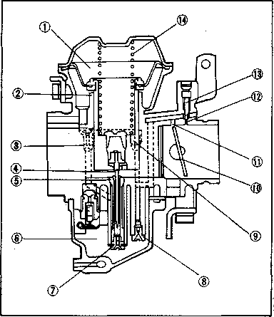
Section View
| 1 | Diaphragm | 8 | Pilot Jet |
| 2 | Piston valve | 9 | Pilot Air Jet |
| 3 | Main air jet | 10 | Throttle Valve |
| 4 | Jet needle | 11 | By-pass hole |
| 5 | Needle jet | 12 | Pilot Outlet |
| 6 | Float chamber |
13 | Pilot Screw |
| 7 | Main jet | 14 | Spring |
Specifications
| Main jet | #106 |
| Jet needle | Y-18 |
| Pilot jet | #41 |
| Starter jet | #43 |
| Fuel level | 1.0 ± 1 mm (0.0394 ± 0.039 in.) |
| Pilot screw | Preset |
| Float valve seat | 02.0 |
| Engine idle speed | 1,100 +50 r/min |
CAUTION: The pilot screw settings are adjusted for maximum performance at the factory attempt to change these settings as any alteration will decrease engine performance.
CARBURETOR
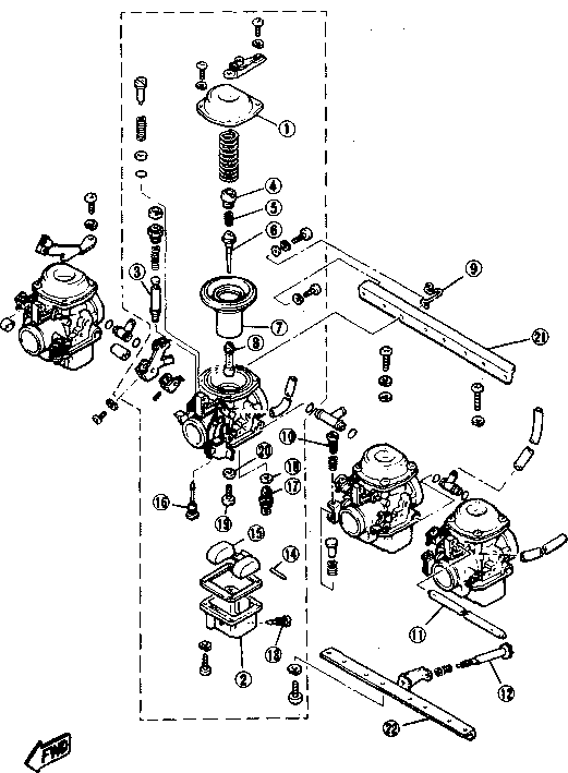
| 1. | Vacuum chamber cover | 12. | Throttle stop screw |
| 2. | Float chamber cover | 13. | Drain screw |
| 3. | Starter plunger | 14. | Float pin |
| 4. | Jet needle cover | 15. | Float |
| 5. | Set spring | 16. | Pilot jet |
| 6. | Jet needle | 17. | Float valve |
| 7. | Vacuum piston | 18. | Float valve washer |
| 8. | Main nozzle | 19. | Main jet |
| 9. | Clutch wire clip | 20. | Main jet washer |
| 10. | Synchronizing screw | 21. | Upper support plate |
| 11. | Starter lever shaft | 22. | Lower support plate |
FUEL LEVEL
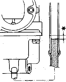
* 1.0 ± 1 mm (0.0394 ± 0.039 in)
Disassembly
CAUTION: Separation of the carburetor is not recommended. Usual disassmebly for cleaning and inspection is not necessary to separate the carburetors. The carburetor body support screws are locked with a locking compound such "LOCTITE". If the carburetors are separated, misalignment will result.
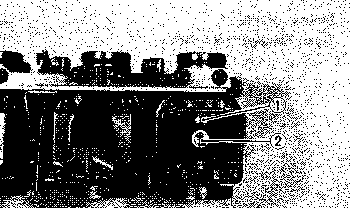
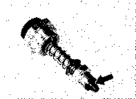
Remove:
• Vacuum chamber cover
• Vacuum piston
• Jet needle
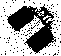
• Main air jet 1
• Pilot air jet 2
• Main nozzle
• Starter plunger
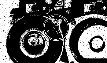
Remove:
• Float chamber cover
• Pilot jet 1
• Main jet 2
Remove:
• Float pin 1
• Float
• Float valve
• Float valve seat
Inspection
Check:
• Carburetor body and fuel passage
If contaminated: Wash carburetor in petroleum-based solvent (Do not use any caustic carburetor cleaning solution). Blow out all passages and jets with compressed air.
• Floats
If damaged, replace.
Check:
• Float needle valve and seat
Wear, contamination -» Replace as a set.
Check:
• Vacuum piston and rubber diaphragm
Scratches (piston), Tears (diaphragm) -> Replace as a set.
• Jet needle
Bends, wear -> Replace.
Check:
• Starter plunger
Wear, damage -> Replace.
Assembly
Reverse disassembly steps. Pay close attention to installation of vacuum piston diaphragm and location of each jet.
NOTE: Note position of tab on diaphragm. This tab must be placed in the cavity of the carburetor body during assembly.
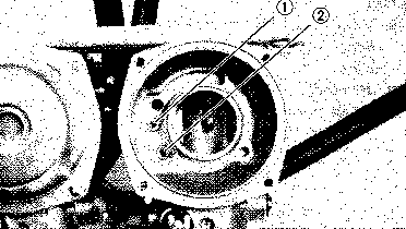
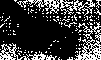
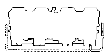
If the carburetors are separated, place the carburetors on a surface plate 2 and install lower 1 and upper support plate.
Apply loctite ® Stud N' Bearing Mount (red) to securing screws.
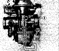
Fuel level Adjustment
NOTE: Place motorcycle on level surface before checking fuel level.
Connect:
• Fuel level gauge 1 or 6 mm (0.24 in.) vinyl pipe.
Place:
• Fuel level gauge to carburetor mixing chamber body.
Loosen:
• Drain screw 2 .
Set:
• Fuel cock to "ON" or "RES" and start engine. Stop it after a few minutes.
Check:
• Fuel level 1 should be within specified range.
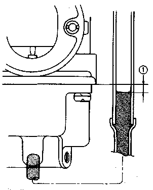
Fuel level
1.0 ± 1 mm (0.0394 ± 0.039 in.) below from the carburetor mixing chamber body edge.
NOTE: Fuel level of each left and right side carburetor shouled be equal. If not, place a suitable size of wooden piece or the like under the center stand and adjust then check fuel level again.
• Remove carburetors and check fuel valve and float assembly if fuel level is not within specified range.
• If no damage is found in these parts, adjust float level by slightly bending tang 1 of float. Recheck fuel level.
• Repeat these steps for other carburetors.
AIR CLEANER AND CRANKCASE VENTILATION SYSTEM
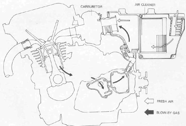
Refer to AIR FILTER for the air cleaner maintenance.
- Printer-friendly version
- Log in to post comments