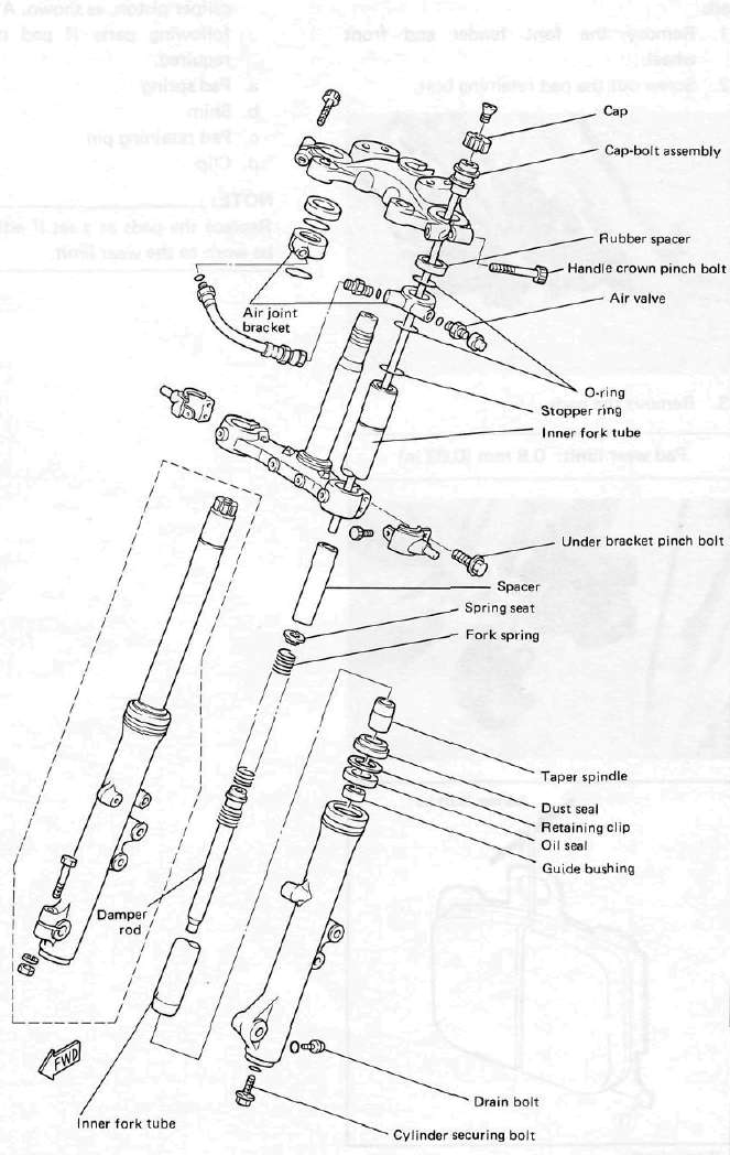
Front fork disassembly
Warning:
Securely support the motorcycle so it won't fall over when the front wheel and fork legs are removed.
1. Remove the cap from the fork air valve and depress the valves until the air pressure escapes completely from both fork legs.
2. Disconnect the speedometer cable from the speedometer drive unit.
3. Remove the brake calipers from the fork legs.
4. Remove the front wheel.
5. Remove the front fender.
6. Loosen the fork pinch bolts in the handle crown and underbracket.
7. Remove the fork assembly from the handle crown and air valve bracket.
8. Remove the spring wire circlips from the outside of the fork legs, and remove the fork legs from the under bracket.
NOTE:
Perform the fork leg disassembly and reassembly procedures on one fork leg at a time.
9. Remove the cap bolt, and remove the spring seat and fork spring.
10. Inspect the o-ring on the cap bolt, and replace the o-ring if it is damaged.
11. Over a drain pan, turn the fork leg upside down and slowly pump the fork oil out of the fork leg.
12. Remove the damper rod bolt from the bottom the fork leg. (Using special tool)
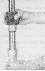
13. Hold one hand over the top of the fork leg, and turn the leg upside down so the damping rod and rebound spring slide down and out of the fork leg; take care not to let the damper rod fall to the ground, as it may be damaged.
14. With the fork leg upright, use a propane torch to heat the top of the slider lightly, and remove the dust seal with a thin screwdriver. Take care not to scratch the inner tube. Discard the dust seal.
CAUTION:
Do not apply too much heat to the slider, as the paint will be damaged.
15. Remove the retaining clip.
16. Hold the fork leg horizontally, securely clamp the axle-mounting boss of the slider in a vise with soft jaws, and again heat the top of the slider.
17. Remove the oil seal and guide bushing from the outer fork tube.
18. Remove all components of the oil lock valve assembly and inspect them; replace the assembly if there are any damaged components.
19. Clean all components of the fork leg and inspect them; replace any worn or damaged components prior to reassembly.
Front fork reassembly
1. Install the rebound spring on the damper rod.
2. Install the damper rod in the inner fork tube, and allow it to slide slowly down the tube until it protrudes from the bottom.
3. Place the taper spindle over the end of the damper rod, and insert the inner fork tube into the outer fork tube.
4. Apply a thread-locking compound such as Loctite® to the threads of the cylinder securing bolt, install the bolt in the damper rod, and torque it to specification. (Using special tool 90890-04084.)
Tightening torque: 20 Nm (2.0 m-kg, 14 ft-lb)
5. Install the guide bushing in the special 36 mm (1.4 in) fork tool (TLM-11080-10-00 or YM-08010). Use the tool to align the bushing in the top of the slider.
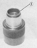
1. Guide bushing
6. Remove the large part of the fork tool, place the small part (TLM-11080-10-01 or YM-08010-1) on the guide bushing, and use the large part of the tool to drive in the bushing.
7. Oil and install a new oil seal in the top of the slider with the special tool. Making sure the beveled edge faces upward.
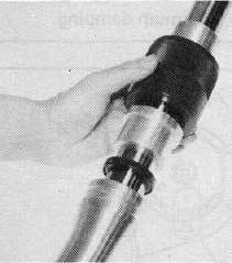
8. Install the retaining clip, and gently tap the dust seal into place with the special tool.
9. Pour the specified amount of the recommended fork oil into the inner fork tube.
Fork oil capacity: 257 cm3, (9.0 Imp oz, 8.7 US oz)
Recommended oil: Yamaha Fork Oil 10wt or SAE 10W30 type SE motor oil
10. Place the fork spring, spring seat, and spacer in the inner fork tube. Install the cap bolt assembly and tighten to specification.
Tightening torque: Cap bolt 30 Nm (3.0 m-kg, 22 ft-lb)
CAUTION:
To tighten the cap-bolt assembly first make sure the damper adjustment rod is fitted correctly in the semicircular hole in the top of the damper rod. If the adjusting rod is not put in this hole, the cap-bolt assembly will not touche the inner fork tube. If this is the case, turn the cap-bolt assembly until the adjusting rod falls into the hole in the damper rod; the cap-bolt assembly will then touch the inner fork tube so you will able to tighten the cap-bolt assembly. Do not force the cap-bolt assembly; you could damage the adjusting rod and ruin the unit.
11. Slide the fork into the underbracket, and install the stopper ring.
12. Apply a light coat of lithium soap base grease to the o-rings in the air joint bracket.
13. Push the fork assembly into the air joint bracket, rubber spacer and handle crown.
When inserting the fork into the air joint bracket, grease the air joint bracket o-ring, and after insertion, make sure the o-ring fits correctly in the groove.
14. Torque the pinch bolts in the handle crown and underbracket.
Tightening torque: 20 Nm (2.0 m-kg, 14 ft-lb)
15. Install the cap onto the cap bolt. For the procedure, refer to "Front fork oil change".
16. Install the proper amount of air pressure in the fork legs. Take care not to exceed the maximum allowable air pressure.
Maximum fork air pressure: 245 kPa (2.5 kg/cm2, 36 psi)
17. Install the air valve caps.
WARNING:
Make sure no oil has contacted any disc brake components; oil will cause diminished braking capacity and damage the rubber components of the brake assembly. Make sure all oil is removed from the brake and actuating piston assemblies before they are reassembled and the motorcycle is operated.
18. Install the front fender, handlebar front wheel, and brake calipers.
19. Connect the speedometer cable to the drive unit, and check the operation of the motorcycle.
- Printer-friendly version
- Log in to post comments