Wheels and Brakes
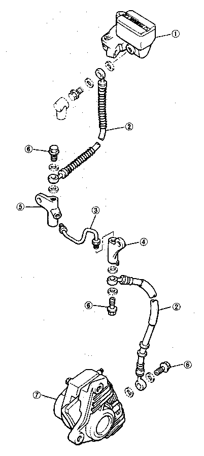
FRONT MASTER CYLINDER
- Read more about Wheels and Brakes
- Log in to post comments
FRONT MASTER CYLINDER
CHASSIS
|
Steering system: |
||||
|
Steering bearing type | ||||
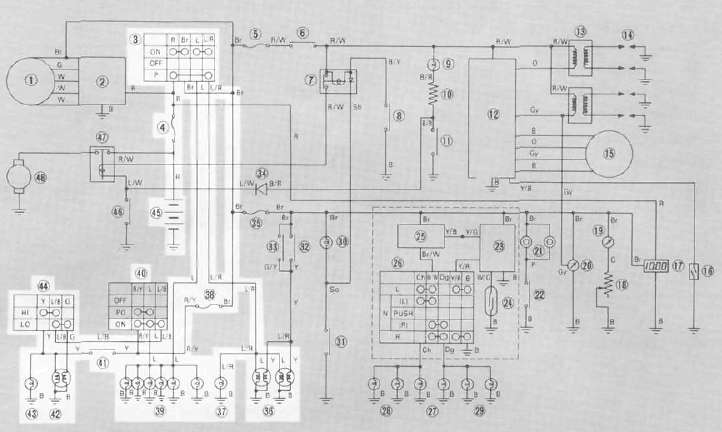
Circuit diagram
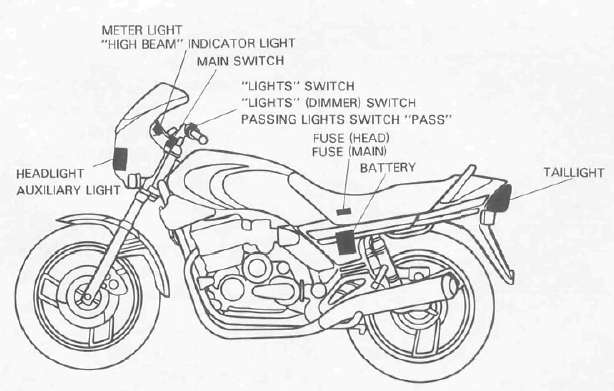
Lighting system tests and checks
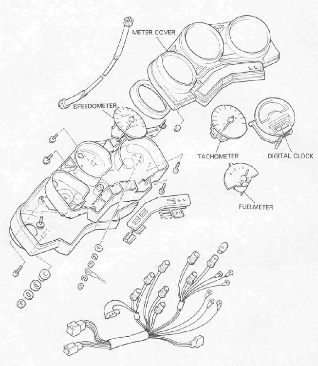
SPEEDOMETER/TACHOMETER
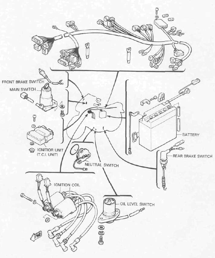
ELECTRICAL 1
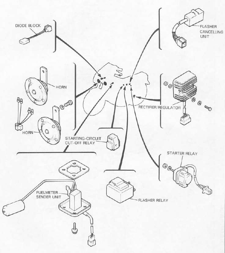
ELECTRICAL 2
WIRING DIAGRAM
This chart specifies torque for standard fasteners with standard I.S.O. pitch threads. Torque specifications for special components or assemblies are included in the applicable sections of this book. To avoid warpage, tighten multi-fastener assemblies in a crisscross fashion, in progressive stages, until full torque is reached. Unless otherwise specified, torque specifications call for clean, dry threads. Components should be at room temperature.
INTRODUCTION
This chapter includes all information necessary to perform recommend inspection and adjustments. These preventative maintenance procedures, if followed, will insure more reliable vehicle operation and a longer service life. The need for costly overhaul work will be greatly reduced. This information applies not only to vehicles already in service, but also to new vehicles that are being prepared for sale. Any service technician performing preparation work should be familiar with this entire chapter.
Inspection
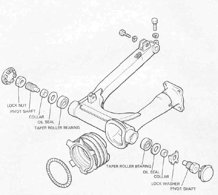
1. Remove the rear wheel and both shock absorbers. Grasp the swing arm and try to move it from side to side as shown. There should be no noticeable side play.

Fuel sender unit
1. Inspection
a. Remove the sender unit from the fuel tank.
b. Use a pocket tester (with ohm x 10 scale) for this check. Connect the pocket tester leads across the green lead and the black lead of the sender unit. The meter should show the following resistance at the specified fuel level. If not replace the sender unit.
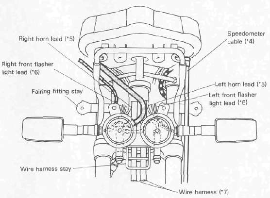
CABLE ROUTING
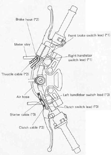
*1: Pass front brake switch lead and right handlebar switch lead behind air hose.
*2: Pass brake hose and throttle cable between air hose and meter stay.
*3: Pass clutch cable, clutch switch lead, left handlebar switch lead and starter cable behind air hose.