Computerized Monitoring System
- Read more about Computerized Monitoring System
- Log in to post comments
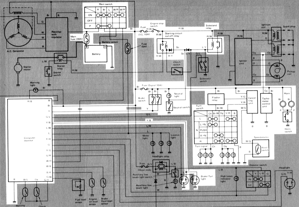
G. SIGNAL SYSTEM
Above circuit diagram shows only signal circuit in wiring diagram.
B. Signal System Tests and Checks
CONSUMER INFORMATION
Note:
The information presented represents results obtainable by skilled drivers under controlled road and vehicle conditions, and the information may not be correct under other conditions.
LIGHTING SYSTEM
Above circuit diagram shows only lighting circuit in wiring diagram.
B. Lighting Tests and Checks
INSPECTION AND REPAIR
A. Cylinder Head Cover
Place head cover on a surface plate. There should be no warpage. Correct by re-surfacing as follows:
Place #400 or #600 grit wet sandpaper on surface plate and re-surface head cover using a figure-eight sanding pattern. Rotate head cover several times to avoid removing too much material from one side.
B. Cylinder Head

13. Remove the front cylinder holding nut and remove the cylinder assembly. It may be necessary to tap the cylinder lightly to loosen it from the base gasket.

14. Remove the rear cam chain guide by loosening the holding bolt.
6. Middle gear (installation only, refer to page 67 for the middle gear adjustment)
a. Install the middle drive gear assembly with the proper size of shim(s) and secure it with the bearing retainers and new "TORX" screws.
Tightening torque: 2.5 m-kg (18 ft-lb)
1. Shims
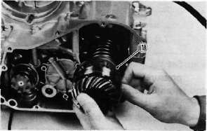
L. Lower Crankcase
1. Remove the dowel pin and "O-ring".
2. Remove the shift fork guide bar and shift forks. The shift forks are identified by numbers cast on their sides.
3. Remove the bolt securing the shift cam locating pin and remove the stopper plate and locating pin.
4. Remove the neutral switch.
ENGINE ASSEMBLY AND ADJUSTMENT
A. Important Information
1. Gasket and seal
All gaskets and seals should be replaced when an engine is overhauled. All gasket surfaces and oil seal lips must be cleaned.
2. Properly oil all mating engine and transmission parts and bearings during reassembly.
3. Circlip
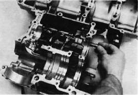
I. Crankshaft
1. Crankshaft run-out
Support the crankshaft at both ends on V-blocks. Measure the amount of crankshaft run-out on the main bearing journals with a dial gauge while rotating crankshaft.
Run-out limit: 0.040 mm (0.0016 in)
If run-out exceeds limit, replace crankshaft.
2. Inspection of bearings