Chapter 5, CHASSIS
Chapter 5, CHASSISWheels
Wheels xjcdadmin Thu, 04/23/2009 - 15:15CHAPTER 5. CHASSIS
1. Place the motorcycle on the center stand.
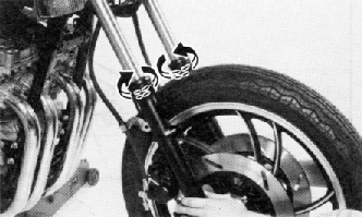
2. Remove the front fender securing bolts and remove the fender.
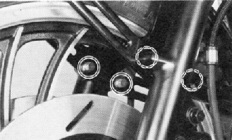
3. Remove the cotter pin and wheel axle nut.
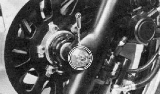
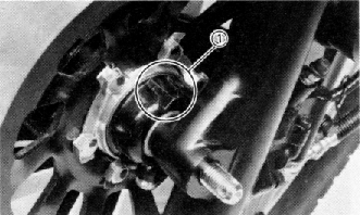
Remove the speedometer cable holder securing bolt.
1. Pinch bolt
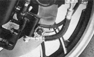
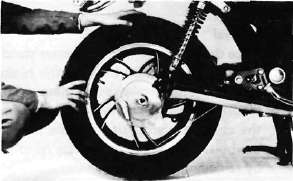
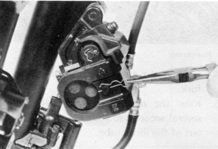
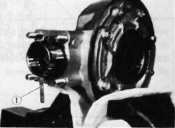
5. Loosen the pinch bolt securing the axle.
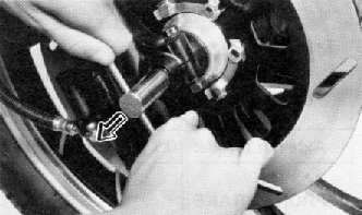
6. Remove the axle shaft and the front wheel. In this case, make sure the motorcycle is properly supported.
NOTE:
Do not depress the brake lever when the wheel is off the motorcycle as the brake pads will be forced to shut.
7. Lower the wheel until the brake discs come off the calipers. Turn the calipers outward so they do not obstruct the wheel and remove the wheel.
B. Front Axle Inspection
Remove any corrosion from the axle with fine emery cloth. Place the axle on a surface plate and check for bends. If bent, replace axle. Do not attempt to straighten a bent axle.
C. Front Wheel Inspection
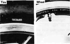
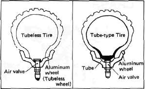
This motorcycle is equipped with aluminum wheels designed to be compatible with either tube or tubeless tires.
Tubeless tires are installed as standard equipment.
WARNING:
Do not attempt to use tubeless tires on a wheel designed for use only with tube-type tires. Tire failure and personal injury may results from sudden deflation.
|
Tube-type Wheel > |
Tube-type Tires Only |
|
Tubeless-type Wheel > |
Tube-type or |
|
WARNING:
When using tube-type tires, be sure to install the proper tube also.
Refer to 'Tubeless Tire and Aluminum Wheel Manual" for the proper tubeless and aluminum wheel servicing.
1. Check for cracks, bends or warpage of wheels. If a wheel is deformed or cracked, it must be replaced.
2. Check wheel run-out. If the deflection exceeds the tolerance below, check the wheel bearings or replace the wheel as required.
|
Rim-run-out limits: |
Vertical |
- 2 mm (0.079 in) |
Lateral |
- 2 mm (0.079 in) |
3. Check wheel balance. Rotate the wheel lightly several times and observe resting position. If the wheel is not statically balanced, it will come to reset at the same position each time. Install an appropriate balance weight at lightest position (at top).
NOTE:
The wheel should be balanced with the brake disc installed.
4. After installing a tire, ride conservatively to allow the tire to seat itself on the rim properly. Failure to allow proper seating may cause tire failure resulting in damage to the motorcycle and injury to the rider.
5. After repairing or replacing a tire, check to be sure the valve stem lock nut is securely fastened. If not, torque it as specified.
Tightening torque: 0.15 m-kg (1.1 ft-lb) !
D. Replacing Wheel Bearings
If the bearings allow play in the wheel hub or if wheel does not turn smoothly, replace the bearings as follows:
1. Clean the outside of the wheel hub.
2. Drive the bearing out by pushing the spacer aside and tapping around the perimeter of the bearing inner race with a soft metal drift pin and hammer. The spacer "floats" between the bearings. Both bearings can be removed in this manner.
WARNING:
Eye protection is recommended when using striking tools.
3. To install the wheel bearing, reverse the above sequence. Use a socket that matches the outside race of the bearing as a tool to drive in the bearing.
CAUTION:
Do not strike the center race or balls of the bearing. Contact should be made only with the outer race.
. For reassembly, follow the procedure below with case;
a. Install the speedometer cable holder securing bolt.
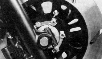
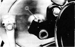
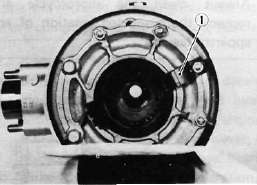
b. Make sure the projecting portion (torque stopper) of the speedometer housing is positioned correctly.
1. Torque stopper
c. Tighten the axle nut and install a new cotter pin.
Axle nut torque: 10.7 m-kg (77.5 ft-lb)
d. Install the front fender.
e. Before tightening the pinch bolt, compress the front forks several times to make sure of proper fork operation. With the axle pinch bolt loose, work the right fork leg back and forth until the proper clearance between the disc and caliper bracket on the front is obtained.

f. Tighten the axle pinch bolt.
Axle pinch bolt torque:2.0 m-kg (14.5 ft-lb)
REAR WHEEL
A. Removal
1. Place the motorcycle on the center stand.
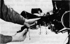
2. Remove the tension bar and the brake rod from the brake shoe plate. The tension bar can be removed by removing the cotter pin and nut from the tension bar bolt. The brake rod can be removed by removing the adjuster.
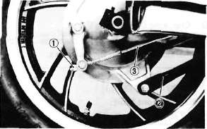
1. Adjuster 2. Tension bar 3. Brake rod
3. Remove the axle nut cotter pin and axle nut.
4. Loosen the rear axle pinch bolt and pull out the rear axle.
1. Pinch bolt
5. Move the wheel to the right side to separate it from the final gear cases and remove the rear wheel.
Brakes
Brakes(Note: see previous section "Wheels" for removal of wheels)
B. Checking Brake Shoe Wear
1. Measure the outside diameter at the brake shoes with slide calipers.
Front brake shoe diameter:
180 mm (7.09 in) Replacement limit:
176 mm min. (6.93 in)
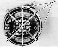
a. Measuring points
2. Remove any glazed areas from the brake shoes using coarse sand paper.
C. Brake Drum
Oil or scratches on the inner surface or the brake drum will impair braking performance or result in abnormal noises.
Remove oil by wiping with a rag soaked in lacquer thinner or solvent.
Remove scratches by lightly and evenly polishing with emery cloth.
D. Brake Shoe Plate
Remove the camshaft and grease. If the cam face is worn, replace.
NOTE:
Before removing the cam lever, put a match mark on the cam lever and camshaft to indicate their positions for easy assembly.
E. Rear Axle Inspection
(See Front Wheel, Axle Inspection Procedure.)
F. Replacing Wheel Bearings
Rear wheel bearing replacement is similar to the procedure for the front wheel.
G. Rear Wheel Inspection
(See Front Wheel, Inspection Procedures)
H. Installing Rear Wheel
1. Lightly grease lips of rear wheel oil seals.
2. Install the wheel assembly and axle.
NOTE:
When installing the rear wheel, be sure the splines on the wheel hub fit into the final gear case. Lightly apply grease to the gear teeth.
Always use a new cotter pin on the axle nut.
Tightening torque:
Axle nut: 10.7 m-kg (77.4 ft-lb) Axle pinch bolt: 0.6 m-kg (4.5 ft-lb)
FRONT BRAKE
CAUTION:
Disc brake components rarely require disassembly. Do not disassemble components unless absolutely necessary. If any hydraulic connection in the system is opened, the entire system should be disassembled, drained, cleaned and then properly filled and bled upon reassembly. Do not use solvents on brake internal components. Solvents will cause seals to swell and distort. Use only clean brake fluid for cleaning. Use care with brake fluid. Brake fluid is injurious to eyes and will damage painted surfaces and plastic parts.
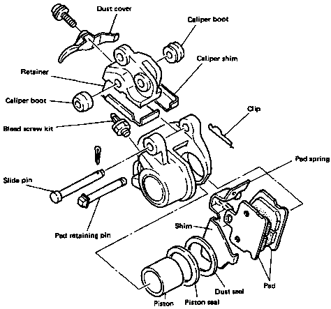
Caliper Pad Replacement
It is not necessary to disassembly the brake caliper and brake hose to replace the brake pads.
1. Remove the front fender and front wheel.
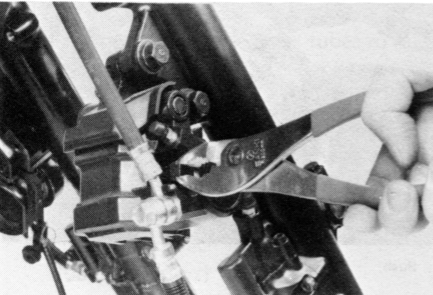
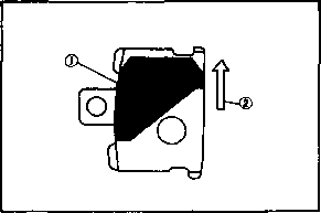
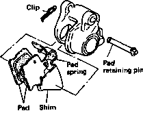
2. Unhook the pad retaining pin clip and remove the clip.
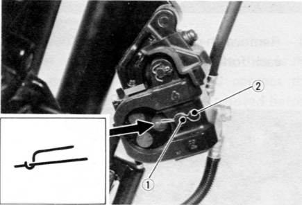
1. Pad retaining pin 2. Clip
3. Pull out the pad retaining pin.
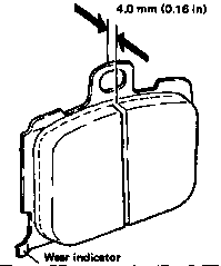
4. Remove the pads.
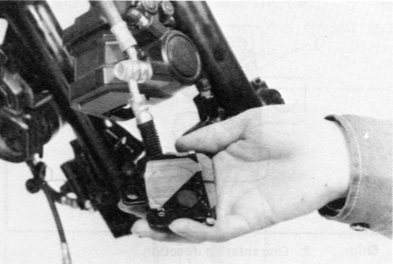
Pad wear limit: 4.0 mm (0.16 in)
5. Install the new brake pads and shims. Before installing the pads, install the shim on the back plate which faces the caliper piston, as shown. Also replace the following parts if pad replacement is required.
a. Pad spring
b. Shim
c. Pad retaining pin
d. Clip
NOTE:
Replace the pads as a set if either is found to be worn to the wear limit.
1. Shim 2. Disc rotating direction
Front Forks
Front ForksXJ750RH Front Fork Disassembly/Reassembly
The XJ750RH front fork has a top and bottom bushing for the inner tube to ride in (reducing friction). Since the top bushing is pressed into the top of the outer tube, it is necessary to remove the oil seal before the inner tube may be removed from the outer tube. The procedure is as follows:
CONVENTIONAL FORK

XJ750RH FORK

Disassembly
1) Disconnect the speedometer cable and brake calipers and remove the front wheel. Place a wooden wedge or other object into the caliper assemblies to prevent the brake pads from falling out. Remove the front fender.
2) Release air from forks by depressing air valve stem.
3) Remove plunger case securing bolts and remove plunger case from anti-dive unit.

4) Loosen pinch bolts on triple clamps holding inner tube.
5) Slide inner tube from triple clamp until air valve ring can be removed (Note: Apply even pressure to both sides of ring during removal) and remove wire ring from inner tube.
6) Remove fork leg.
7) Remove dust cover, circlip and washer from the outer tube.
Note: Do not damage the inner tube surface during dustcover removal.
8) Remove rubber cap from top of inner tube.
9) The spring seat and spring are retained by a stopper ring. Depress stopper seat and remove stopper ring.
10) Remove spring seat and fork spring.
Note: Do not drain fork oil.
11) Reinstall air valve ring on inner tube.
12) Set the inner tube with approximately 50 mm travel at end and completely fill with fork oil.
13) Reinstall spring seat and stopper ring.
14) Slightly depress inner tube and hold air valve stem until all air is bled from fork.
15) Using a press, slowly contract the inner tube in the outer tube until oil seal comes out or oil leaks from outer portion of oil seal.
Note: If the inner tube is abruptly contracted or if air remains in the inner tube, the oil may spurt out or the oil seal may spring out. Never touch the inner tube during disassembly.

16) Remove stopper ring and spring seat then drain oil.
17) Remove oil seal from top of inner tube.
18) Remove alien bolt from bottom of outer tube.
19) Hold the fork leg horizontally, securely clamp the axle mounting boss of the outer tube in a vice with soft jaws, and remove bushing from top of outer tube by carefully but forcefully withdrawing the inner tube.
Note: 1) Excessive force will damage the bottom and/or the top bushing. Damaged bushing must be replaced. 2) Avoid bottoming the inner tube in the outer tube during the above procedure, as the oil lock valve assembly will be damaged.
Reassembly
Before reassembling, clean and inspect all parts and replace when necessary. Bottom Bushing Installation
1) Install using only tapered end of inner tube to expand bush.

2) Reinstall compression cylinder in inner tube and, with assembly inverted, assemble washer, wavy washer and collar on projection of compression cylinder and install in outer tube.

Note: Place outer tube over inner tube assembly when installing to prevent washers and collar from coming detached.
3) Install alien bolt through bottom of outer tube and torque to specification using Locktite.
Note: Allen bolt torque — 2.0 kg-mm — Use Locktite When tightening alien bolt, be sure to align anti-dive hole in outer tube and oil lock piece hole.

Top Bushing Installation
4) Install top bushing as per the following two steps:
a) Use large special tool for temporary installation of bushing in outer tube.

b) Complete installation using both small and large special tools.

5) Install "L" section washer on top of bushing and then install oil seal with numbered side up, using special tool (part number TLM-11080-10)

6) Install washer and circlip then install dust cover using special tool.

7) Pour specified amount of oil into inner tube.
Note: Front fork oil (each): 309 cc (10.4 oz.) Recommended oil: SAE 20W After filling, slowly pump the fork up and down to distribute oil.
8) Install spring, seat and stopper ring.
9) Partially install fork under triple clamp then install wire ring and air valve ring.
10) Slide fork leg up and tighten triple clamp bolts.
11) Install front fender, front wheel brake calipers and speedometer cable.
12) Reinstall plunger case.

Warning:
When reinstalling the plunger case, use utmost care to free the inside of the case from any mineral oils (eg. engine oil, fork oil, etc.). Otherwise, such oils will deteriorate the actuating piston o-ring, with the resultant leakage of the brake fluid'.
Note: Tightening torque: 0.4 mm-kg (2.9 ft-lb — Use Locktite)
Maximum Air Pressure: 2.5 kg/cm2 (36 psi). Do not exceed this amount.
Special Tool
Part Number TLM-11080-10
This tool will be available from the Yamaha Parts Department around August 1981.
Anti Dive System
Anti Dive System
ANTI-DIVE SYSTEM

Normal oil flow -- no brakes applied.
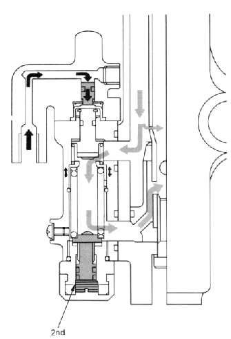
Oil flow as brakes are applied. Brake fluid pressure begins to move actuating piston against the small spring, pushing piston against seat, thereby restricting oil flow from the outside of the fork tube to the inside.
Adjuster fully extended -- all lines showing.
Oil flow as the adjusting bolt is set to the minimum effect. As the fork tries to compress, pressure builds on the seat, overcoming the pressure of the large spring, allowing the seat to move and fluid to pass from outside to inside the tube.
NOTE: Some fluid is always allowed to pass through the restricted passage above the anti-dive ports.

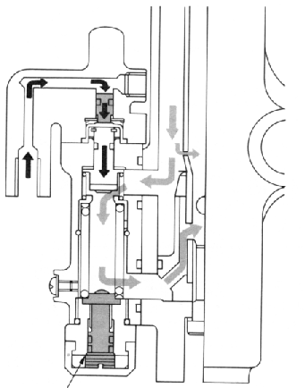
Adjuster fully seated -- head flush with notch.
Oil flow as the adjusting bolt is set to the maximum effect. The bolt applies greater force to the large spring, increasing the pressure required to move the seat.
System inspection
1. Apply the front brake for a few minutes and check to see if any brake fluid leaks out of the pipe joint and/or the vent.
2. Check the fork for fork oil leakage.
3. Turn the anti-dive adjusting bolt to the maximum position.
4. Compress the front forks while applying the front brake. If the front forks are compressed easily, the anti-dive system may be damaged.
Removal
1. Release the air from the front fork by pressing the air valve pin.
2. Remove the drain screw from the anti-dive valve housing and drain the fork oil.
3. Remove the brake hose from the actuating piston housing.
4. Remove the bolts securing the actuating piston housing, and remove the housing from the anti-dive valve housing.

Remove the anti-dive adjusting bolt cover and remove the adjusting bolt seat.
The adjusting bolt can not be removed from its seat.
6. Remove four bolts securing the anti-dive valve assembly and remove the housing assembly from the front fork. Remove two O-rings from the front fork.
Inspection
NOTE:
The anti-dive valve housing can not be disassembled so it must be replaced with a new one if the anti-dive valve malfunction is found.
1. Remove the circlip and remove the actuating piston from the actuating piston housing.

1. Circlip 2. Actuating piston
Do not remove the O-ring from the actuating piston.
2. Check the piston, O-ring, and cylinder for wear, cracks, rust, and/or scrathces. If any damage is found, replace the actuating piston housing assembly.

3. Check the piston separator for cracks and replace if damaged.

4. Check the spring seat rivetted portion of the adjusting bolt for damage. Replace the adjusting bolt seat assembly if damaged.
Assembly
1. Lubricate the actuating piston with clean brake fluid, and carefully insert the piston into the actuating piston housing cylinder until the shoulder of the piston is flush with the cylinder edge.
2. Install the washer and circlip.
3. Install the separator into the actuating piston housing.
4. Install new O-rings around the front fork oil passages.
5. Install the anti-dive valve housing onto the front fork and secure it with four bolts. Torque the bolts to the specification.
Tightening torque: 0.8 m-kg (5.8 ft-lb)
6. Install the actuating piston housing onto the anti-dive valve housing and secure it with two bolts. Torque the bolts to the specification.
Tightening torque: 0.4 m-kg (2.9 ft-lb)
7. Install a new O-ring onto the adjusting bolt seat and apply a thread locking compound. Install the adjusting bolt seat assembly and tighten it to the specification.
Tightening torque: 2.0 m-kg (14.5 ft-lb)
8. Connect the brake hose to the actuating piston housing with the union bolt and copper washers. Torque it to the specification.
Tightening torque: 2.6 m-kg (18.8 ft-lb)
9. Pour the specified amount of front fork oil into the fork inner tube.
Front fork oil capacity (each leg):
309 cc (10.5 oz) Recommended oil:
Yamaha fork oil 20Wt or equivalent
10. Add proper brake fluid into the brake reservoir being careful not to spill or overflow.
11. Connect the clear plastic tube of 4.5 mm in inside diameter tightly to the actuating piston housing bleed screw. Put the other end of the tube into a container.
12. Slowly apply the brake lever several times. Pull in the lever. Hold the lever in the "on" position. Loosen the bleed screw. Allow the lever to travel slowly toward its limit. When the limit is reached, tighten the bleed screw. Then release the lever.
13. Repeat the above step until all air bubbles are removed from the brake line. It may be necessary to bleed the caliper cylinder in the same manner.
NOTE:
If the bleeding is difficult, it may be necessary to let the brake fluid in the system stabilize for a few hours and repeat the bleeding procedure.
14. Fill the fork with air using a manual air pump or other pressurized air supply.
Standard air pressure: 0.4 kg/cm2 (5.7 psi)
15. Adjust the anti-dive adjusting bolt.
Steering Head
Steering Head
STEERING HEAD
A. Adjustment
Refer to "D. Reassembly" (below) for steering head adjustment procedure.
B. Removal
1. Remove the front wheel, front forks and handlebars.
2. Remove the front brake pipe junction.
3. Loosen the steering stem (upper bracket) pinch bolt.
4. Remove the stem bolt and steering crown.
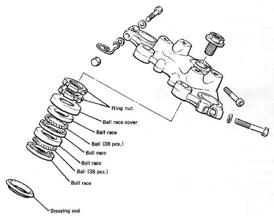
5. Remove the top fitting nut (ring nut).
6. Support the steering stem (under bracket) and remove the bottom fitting nut (ring nut).
7. Remove the top bearing race and all of the bearing balls from the upper bearing
Ball quantity (upper and lower): 38 pieces.
C. Inspection
1. Wash the bearings in solvent.
2. Inspect the bearings for pitting or other damage. Replace the bearings if pitted or damaged. Replace the races when bearing balls are replaced.
3. Clean and inspect the bearing races. Spin the bearings by hand. If the bearings are not smooth in their operation in the races, replace bearing balls and races.
1. Bearing race
D. Reassembly
1. Grease the bearings and races with wheel bearing race.
2. Install the steering stem (under bracket), bearing balls, and races.
3. Install the bottom fitting nut. Tighten it to approximately 2.5 m-kg (18 ft-lb) and loosen it approximately 1/4 turn.
4. While holding the bottom fitting nut with the ring nut wrench, tighten the top fitting nut securely.
5. Continue reassembly in the reverse of disassembly order.
6. When assembly is complete, check the steering stem by turning it from lock to lock. If there is any binding or looseness, readjust the steering stem tightness.
Pinch bolt torque: 2.0 m-kg (14.5 ft-lb)
Steering stem bolt torque 5.4 m-kg (39.1 ft-lb)
Swing Arm, Rear Shocks, Cables and Fittings
Swing Arm, Rear Shocks, Cables and FittingsSWING ARM
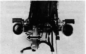
A. Inspection
1. Free play inspection
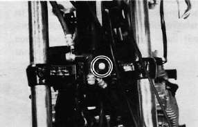
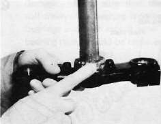
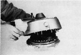
Remove the rear wheel and both shock absorbers. Grasp the swing arm and try to move it from side to side as shown. There should be no noticeable side play.
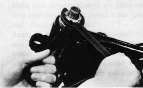
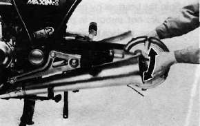
2. The swing arm is mounted on tapered bearings. Move the swing arm up and down as shown. The swing arm should move smoothly, without tightness, binding or rough spots that could indicate damaged bearings.
B. Adjustment
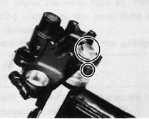
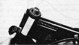
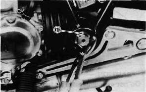
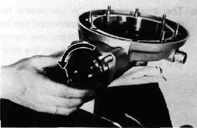
1. Remove the pivot shaft cap from the right side of the swing arm.
2. Loosen the right pivot shaft lock nut and tighten the pivot shaft (clockwise) to 0.5-0.6m-kg(43~52in-lb).
3. Tighten the pivot shaft lock nut.
NOTE:
Do not allow the pivot shaft to turn while tightening the lock nut.
Pivot shaft lock nut torque: 10m-kg (72.3ft-lb)
C. Removal
1. Remove the middle gear flange holding bolts.
2. Remove the rear wheel and shock absorbers.
3. Remove the final gear assembly.
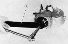
4. Install the drive shaft puller attachment (special tool) on the side hammer bolt (special tool). Insert the 2 arms of the puller into the mouth of drive shaft housing. Tighten the 2 arms around the toothed flange of the drive shaft out of the universal joint. Pull out the drive shaft from the housing.
1. Drive shaft 2. Drive shaft puller 3. Slide hammer
5. Remove the swing arm pivot caps, the pivot shafts and the swing arm.
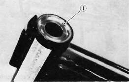
D. Inspection and Lubrication
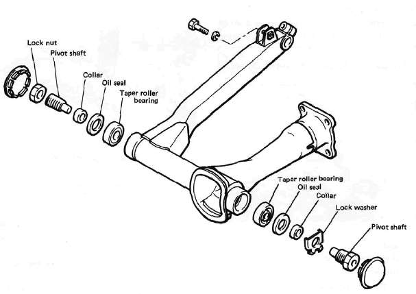
1. Remove the oil seals and the bearings. Inspect the bearings for pitting or other damage. Make sure that the bearings roll freely. If a bearing is damaged, both bearings and both sets of inner and outer bearing races should be replaced.
CAUTION:
Do not use compressed air to spin the bearings dry. This causes damage to the bearing surfaces.
NOTE:
When installing new bearings, grease liberally with lithium base, waterproof wheel bearing grease.
2. Always replace the grease seals when bearings are removed.
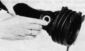
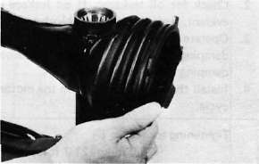
3. Examine the rubber boot for damage. Replace if damaged.
E. Installation
Installation of the swing arm can be accomplished by reversing the removal procedure. Observe adjustment procedures for obtaining equal frame/swing arm spacing.
Tightening torque: Left side pivot shaft: 10 m-kg (72.3 ft-lb) Right side pivot lock nut:
10 m-kg (72.3 ft-lb)
CAUTION:
A lock washer for left side pivot bolt must be replaced with a new one and the tab should be bent over along the bolt flat after tightening.
1. Lock washer
REAR SHOCK ABSORBER
A. Removal
1. Remove one (1) rear shock absorber at a time, inspect and reinstall before removing the other.
B. Inspection
1. Check the rod. If it is bent or damaged, replace the shock absorber.
2. Check for oil leakage. If oil leakage is evident, replace the shock absorber.
3. Operate shock absorber rod to check damping. There should be no noticeable damping as the shock extends.
4. Install the shock absorber on the motorcycle.
Tightening torque:
3.0 m-kg (21.7 ft-lb)
CABLE AND FITTINGS A. Cable Maintenance
NOTE:
See Maintenance and Lubrication intervals charts. Cable maintenance is primarily concerned with preventing deterioration through rust and weathering and providing proper lubrication to allow the cable to move freely
within its housing. Cable removal is straight forward and uncomplicated. Removal will not be discussed within this section.
WARNING:
Cable routing is very important. For details of cable routing, see the cable routing diagrams at the end of this manual. Improperly routed or adjusted cables may make the motorcycle unsafe for operation.
1. Remove the cable.
2. Check for free movement of cable within its housing. If movement is obstruced, check for fraying or kinking of the cable strands. If damage is evident, replace the cable assembly.
3. To lubricate the cable, hold it in a vertical position. Apply lubricant to the uppermost end of cable. Leave it in the vertical position until lubricant appears at the bottom. Allow any excess to drain and reinstall the cable.
NOTE:
Choice of lubricant depends upon conditions and preferences. However, a semi-drying chain and cable lubricant will perform adequately under most conditions.
B. Throttle Maintenance
1. Remove the Phillips head screws from throttle housing assembly and separate the two halves of housing.
2. Disconnect the cable end from the throttle grip assembly and remove the grip assembly.
3. Wash all parts in a mild solvent and check all contact surfaces for burrs or other damage. (Also clean and inspect right-hand end of the handlebar.)
4. Lubricate all contact surfaces with a light coat of lithium soap base grease and reassemble.
NOTE:
Tighten the housing screws evenly to maintain an even gap between the two halves.
5. Check for smooth throttle operation and quick spring return when released and make certain that the housing does not rotate on the handlebar.
Shaft and Rear Drive
Shaft and Rear DriveSHAFT DRIVE
Refer to "CHAPTER 3". for the middle gear.
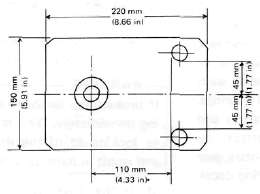
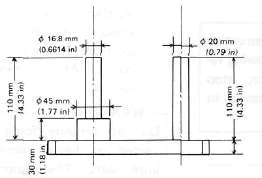
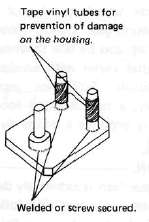
The following special tools are not available but can be constructed for the final gear
disassembly and assembly:

A. Troubleshooting
1. The following conditions may indicate damaged shaft drive components:
|
Symptoms |
Possible damaged areas |
1. A pronounced hesitation or "jerky" movement during acceleration, deceleration, or sustained speed. (This must not be confused with engine surging or transmission characteristics). 2. A "rolling rumble" noticeable at low speed; a high-pitched whine; a "clunk" from a shaft drive component or area. |
A. Damage to bearings. B. Improper gear lash. C. Gear tooth damage. D. Drive flange/universal joint bolts loose. |
3. A locked-up condition of the shaft drive mechanism; no power transmitted from engine to rear wheel. |
E. Broken drive-shaft. F. Disconnected flange/universal joint connection. G. Broken gear teeth. H. Seizure due to lack of lubrication. I. Small foreign object lodged between moving parts. |
NOTE:
Damage areas A, B, and C above may be extremely difficult to diagnose. The symptoms are quite subtle and difficult to distinguish from normal motorcycle operating noise. If there is reason to believe component(s) are damaged, remove component(s) for specific inspection.
2. Inspection Notes:
a. During coasting, accelerating or decelerating, the "rolling rumble" will increase with rear wheel speed, not engine or transmission gear speeds. However, such noise may also be due to wheel bearings.
b. Noise that varies with acceleration and deceleration: Following incorrect reassembly, a condition of too-little gear lash may produce a whine during deceleration.
.CAUTION:
Too-little gear lash is extremely destructive to gear teeth. If a test ride following reassembly indicates this condition, stop riding immediately to minimize damage to gears.
c. A slight "thunk" must be distinguished from normal motorcycle operation. It will be most noticeable at low speed and could indicate broken gear teeth.
WARNING:
If broken gear teeth are suspected, stop riding immediately. This condition could lead to locking-up of the shaft drive assembly and result in harm to a rider.
d. If the drive flange/universal joint bolts are slightly loose, a "clunk" may be felt when slowly taking off, or when changing from slow acceleration to slow deceleration. At high speed this will result in vibration.
WARNING:
Do not continue riding a motorcycle suspected of having loose flange/universal joint bolts. The components may break, causing injury to a rider.
3. Troubleshooting Chart
Where Basic Conditions "a" and "b" above exist, consider the following Chart:
|
Elevate and spin front wheel. Feel for wheel bearing damage. |
Yes ► |
Replace wheel bearing. (See CHAPTER 5 "Front wheel") |
|
Check rear wheel. Feel for bearing damage. |
No ►
|
Rear wheel bearings and shaft drive bearings probably not damaged. Repeat test or remove individual components. |
|
Remove rear wheel. Check for wheel bearing damage. |
Yes ► |
Replace rear wheel bearing. (See "Rear Wheel" section in this chapter.) |
|
Remove drive shaft components. |
4. Oil Leak Inspection
If a shaft drive component is suspected of leaking oil, first thoroughly clean the entire motorcycle. The apparent location of an oil leak on a dusty motorcycle may be misleading. Dry the motorcycle and apply a leak-localizing compound or a dry-powder spray that will limit the flow of any leaking oil. Operate the motorcycle prepared in this way for the distance necessary to precisely locate the leak. There are the possibilities that a component housing may have been damaged by road debris or an accident, or a gasket or seal may be cracked or broken. However, on new or nearly new motorcycle an apparent oil leak may be the result of a rust-preventive coating or excess assembly lubrication of seals. Always clean the motorcycle and recheck the suspected location of any apparent leakage.
5. Checking Drained Oil
Whenever a problem is suspected in either the middle or final gear assemblies, drain and inspect the oil. Metal particles on the drain plug or in the oil could indicate a bearing seizure or other problem in the component. However, a small amount of metal particles in the oil is normal.
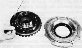
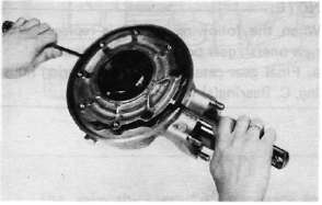
B. Final Gear Removal
1. Remove the rear axle and left shock absorber. Remove the rear wheel (see "Rear Wheel" section in this chapter).
2. Remove the 4 nuts holding the Final Drive unit to the swing arm.
3. Remove the final gear assembly.
C. Gear Lash Check and Adjustment
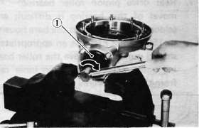
1. Secure the gear case in a vice or other support.
2. Remove one nut from the final gear case stud bolt. Install the gear holder (special tool) over the ring gear surface and stud bolt. Tighten the holder to stud bolt with a nut.
1. Final gear holding tool
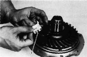
3. Install the final gear lash measurement tool on the gear coupling.
1. Gear lash measurement tool (Final gear)
4. Mount a dial gauge against the lash measurement tool at the scribed mark (60 mm, 2.36 in from the center of the shaft).
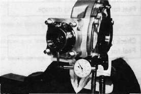
5. Use the special wrench to gently rotate the gear coupling back and forth. Note the lash measurement on the dial gauge.
Final gear lash:
0.25 - 0.50 mm (0.010-0.020 in): When using the measurement tool. 0.1 ~ 0.2 mm (0.004 ~ 0.008 in): Actual gear lash on the final gear teeth.
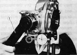
1. Middle and final gear holding tool
6. If the gear lash exceeds the specified limits, adjust as follows:
a. To reduce gear lash, increase the ring gear shim.
b. To increase gear lash, reduce ring gear shim.
1. Ring gear shim
c. If it is necessary to increase the ring gear shim by more than 0.1 mm reduce the thrust washer thickness by 0.1 mm for each 0.1 mm of ring gear shim increase and if it is necessary to reduce shim by more than 0.1 mm, reverse above procedure.
D. Final Gear Disassembly
1. Remove the nuts and bolts holding the bearing housing.
2. Remove the ring gear assembly and thrust washer from the final gear case.
3. Remove the self-locking nut from drive pinion by using the holding tool (special tool) and remove the coupling.
1. Middle and final gear holding tool
4. Remove the drive pinion bearing retainer with the retainer remover (special tool).
CAUTION:
The drive pinion bearing retainer nut is left hand threads. Turn the retainer nut clockwise to loosen.
1. Drive pinion bearing retainer remover
5. Remove the drive pinion and bearing with the slide hammer and adapter (special tool).
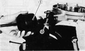
1. Slide hammer 2. Adapter
CAUTION:
This drive pinion removal should be performed only if gearing replacement is necessary. Do not re-use bearings or races after removal.
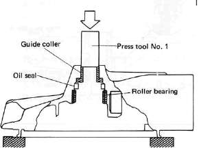
6. Remove the guide collar, oil seal, and roller bearing from the main housing by using the press tool No. 1 (special tool) and a press. Use an appropriate supports for the main housing during this operation. The roller bearing may be re-used if undamaged. Do not re-use oil seal.
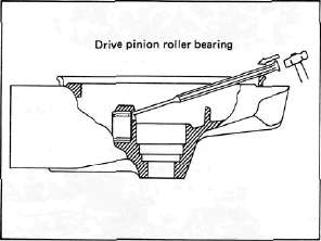
Rear drive pinion roller bearing; removal of this bearing is difficult and seldom necessary. Heat the bare housing to 150°C (302°F). Use an appropriately shaped punch to remove the roller bearing outer race. Remove the inner race from the drive pinion.
E. Final Gear Reassembly
1. Install the new rear drive pinion roller bearing. Heat the bare bearing to 150°C (302°F) and use an appropriately adapter to install the roller bearing outer race. Install the inner race onto the drive pinion.
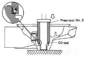
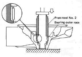
2. Using the press tool No. 2 (special tool) and a press, install the guide collet, new oil seal, and roller bearing into the main housing in that order.
NOTE:
The removed roller bearing can be used if undamaged; however, we recommend replacement with a new one.
3. Final drive/ring gear positioning
NOTE:
When the following part(s) is replaced with new one(s), gear positioning is necessary: a. Final gear case, b. Ring gear bearing housing, C. Bearing(s)
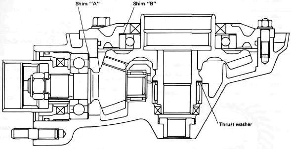
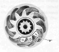
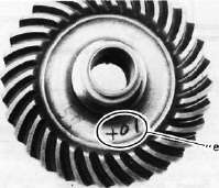
a. The shim thickness "A" necessary for the drive pinion gear positioning can be calculated from the information found on the final gear case and on the drive gear end.
1. Size number
To fined shim thickness "A" use the
formula:
A = a -b
Where:
a = a numeral (usually a decimal number) on the gear near the tooth and either added to or detracted from the nominal size "84".
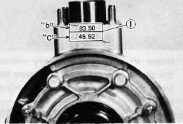
b = a numeral on the gear case appearing as a whole figure (ie. 83.50).
Example:
1) If the pinion gear is marked "+01"....."a" is 84.01.
2) If the gear case is marked "83.50".
A = 84.01 - 83.50 A = 0.51
Then the necessary shim thickness is 0.51mm.
Shim sizes are supplied in the following thicknesses:
0.15 mm, 0.30 mm, 0.40 mm, 0.50 mm, 0.60 mm.
Because the shims can only be selected in 0.05 mm increments the following chart should be used when encountering last digits that are not 5 or zero (0):
|
Last digits |
Rounding |
0,1,2 |
0 |
3, 4, 5, 6, 7 |
5 |
8,9 |
10 |
b. The shim thickness "B" necessary for the ring gear positioning can be calculated from the information found on the final gear case, ring gear, and bearing.
To find shim, thickness "B" use the
formula:
B = c + d-(e + f)
Where:
c= a numeral on the gear case appearing as a whole figure (ie. 45.52)
d = a numeral (usually a decimal number) on the outside of the ring gear bearing housing and added to the nominal size "3".
e= a numeral (usually a decimal number) on the inside of the ring gear and; either added to or detracted from the nominal size "35.40".
f = a bearing thickness (considered constant)
Distance "f" = 13.00 mm
Example:
1) If the gear case is marked "45.52".
2) If the ring gear bearing housing is marked "35"....."d" is 3.35.
3) If the ring gear is marked "+01" ..... "e" is 35.40 + 0.01 = 35.41.
4) "f" is 13.00.
B = c + d-(e + f)
B = 45.52 + 3.35 - (35.41 + 13.00)
B = 48.87- (48.41)
B = 0.46
Then the necessary shim thickness is
0.41 mm.
NOTE:
Use the chart for the drive pinion shim to select the ring gear shim size.
4. Install the drive pinion gear with the proper size of shim(s) and secure it with the bearing retainer nut with the drive pinion bearing retainer remover (special tool).
NOTE:
The bearing retainer nut is left hand threads; turn the nut to counterclockwise to tighten.
Tightening torque: 11 m-kg (80 ft-lb)
Install the ring gear assembly without the thrust washer. Adjust the gear lash (refer to "C. Gear lash check and adjustment).
Place four pieces of "PLASTIGAGE" between the originally fitted thrust washer and ring gear. Install the gear case onto the ring gear assembly and tighten the nuts and bolts with the specified torque.
Tightening torque;
Bolt/Nut......... 2.3 m-kg
(16.6 fMb)
NOTE:
Do not turn the drive pinion/ring gear when measuring clearance with "PLASTIGAGE".
8. Remove the ring gear assembly and determine the clearance by measuring the width of the flattened "PLASTIGAGE".
1. PLASTIGAGE
Ring gear thrust clearance. 0.1 ~ 0.2 mm
9. If the clearance exceeds the specification above, replace the thrust washer to obtain the proper clearance.
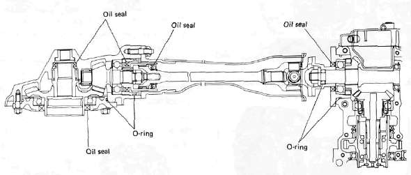
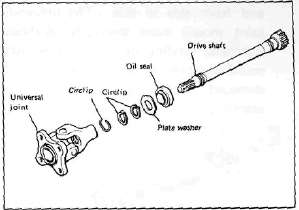
DRIVE SHAFT/JOINT
A. Removal
1. Remove the rear wheel. See "REAR WHEEL A. Removal" in this chapter.
2. Remove the final gear case assembly.
3. Remove the drive shaft. See "SWING ARM removal" in this chapter.
4. To remove the universal joint, it is necessary to remove the swing arm. Remove the universal joint assembly.
B, Inspection
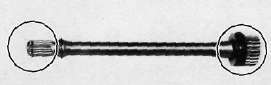
1. Drive shaft
Inspect the shaft splines for wear and/or damage. If excessive, replace the drive shaft.
NOTE:
When installing the drive shaft, lubricate splines with molybdenum di-sulfide grease.
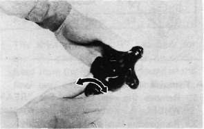
2. Universal joint
a. There should be no noticeable play in the universal joint bearings. If there is any play in the bearing, replace the universal joint assembly.
b. Move the universal joint up and down and from side to side. The universal joint should move smoothly. Without tightness, binding or rough spots that could indicate damaged bearings. If damaged, replace the universal joint assembly.
C. Reinstallation
When installing the drive shaft and the universal joint, reverse the removal procedure. Note the following points:
1. Lubricate the shaft splines with molybdenum di-sulfide grease.
2. Tighten the universal joint securing bolts and final gear case securing nuts with the specified torque:
Final gear case: 4.2 m-kg (30.4 ft-lb) Universal joint: 4.4 m-kg (31.8 ft-lb)